Click here to view as PDF - MICROmanufacturing
Click here to view as PDF - MICROmanufacturing
Click here to view as PDF - MICROmanufacturing

You also want an ePaper? Increase the reach of your titles
YUMPU automatically turns print PDFs into web optimized ePapers that Google loves.
LASERpoints<br />
Fiducials: how <strong>to</strong> be w<strong>here</strong> you need <strong>to</strong> be<br />
Panel Fiducial<br />
Global Fiducial<br />
14 | MARCH/APRIL 2010 | <strong>MICROmanufacturing</strong><br />
When running a job on a l<strong>as</strong>er—or any<br />
other <strong>to</strong>ol—it is frequently required<br />
that the processing <strong>to</strong>olpath be aligned <strong>to</strong> existing<br />
features. Generally, the sharper and<br />
smaller the alignment feature the more accurate<br />
the alignment.<br />
A camera- or optical-b<strong>as</strong>ed vision system<br />
usually is used. The alignment process can be<br />
performed manually or au<strong>to</strong>matically. Accuracies<br />
on the order of microns are possible with<br />
systems that incorporate high-resolution motion<br />
stages and camer<strong>as</strong>, and crisp fiducials.<br />
A fiducial, or fiduciary marker, is an object<br />
in an imaging system’s field of <strong>view</strong> that appears<br />
in the image produced and serves <strong>as</strong> a<br />
point of reference or a me<strong>as</strong>ure. One fiducial<br />
is usually designated “primary” and is used <strong>to</strong><br />
adjust the X/Y offset. Secondary fiducials are<br />
used for other operations. Fiducials are not all<br />
All images: Pho<strong>to</strong>Machining<br />
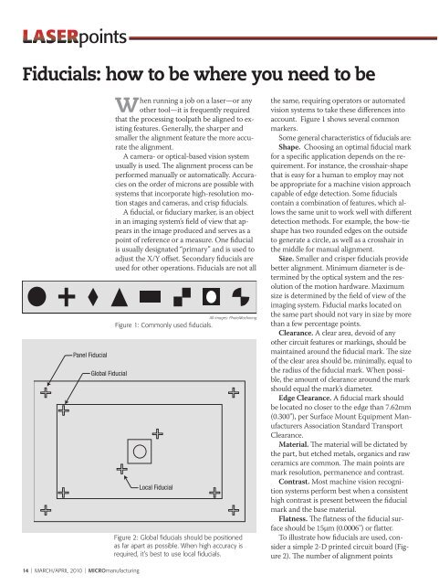
Figure 1: Commonly used fiducials.<br />
Local Fiducial<br />
Figure 2: Global fiducials should be positioned<br />
<strong>as</strong> far apart <strong>as</strong> possible. When high accuracy is<br />
required, it’s best <strong>to</strong> use local fiducials.<br />
the same, requiring opera<strong>to</strong>rs or au<strong>to</strong>mated<br />
vision systems <strong>to</strong> take these differences in<strong>to</strong><br />
account. Figure 1 shows several common<br />
markers.<br />
Some general characteristics of fiducials are:<br />
Shape. Choosing an optimal fiducial mark<br />
for a specific application depends on the requirement.<br />
For instance, the crosshair-shape<br />
that is e<strong>as</strong>y for a human <strong>to</strong> employ may not<br />
be appropriate for a machine vision approach<br />
capable of edge detection. Some fiducials<br />
contain a combination of features, which allows<br />
the same unit <strong>to</strong> work well with different<br />
detection methods. For example, the bow-tie<br />
shape h<strong>as</strong> two rounded edges on the outside<br />
<strong>to</strong> generate a circle, <strong>as</strong> well <strong>as</strong> a crosshair in<br />
the middle for manual alignment.<br />
Size. Smaller and crisper fiducials provide<br />
better alignment. Minimum diameter is determined<br />
by the optical system and the resolution<br />
of the motion hardware. Maximum<br />
size is determined by the field of <strong>view</strong> of the<br />
imaging system. Fiducial marks located on<br />
the same part should not vary in size by more<br />
than a few percentage points.<br />
Clearance. A clear area, devoid of any<br />
other circuit features or markings, should be<br />
maintained around the fiducial mark. The size<br />
of the clear area should be, minimally, equal <strong>to</strong><br />
the radius of the fiducial mark. When possible,<br />
the amount of clearance around the mark<br />
should equal the mark’s diameter.<br />
Edge Clearance. A fiducial mark should<br />
be located no closer <strong>to</strong> the edge than 7.62mm<br />
(0.300"), per Surface Mount Equipment Manufacturers<br />
Association Standard Transport<br />
Clearance.<br />
Material. The material will be dictated by<br />
the part, but etched metals, organics and raw<br />
ceramics are common. The main points are<br />
mark resolution, permanence and contr<strong>as</strong>t.<br />
Contr<strong>as</strong>t. Most machine vision recognition<br />
systems perform best when a consistent<br />
high contr<strong>as</strong>t is present between the fiducial<br />
mark and the b<strong>as</strong>e material.<br />
Flatness. The flatness of the fiducial surface<br />
should be 15μm (0.0006") or flatter.<br />
To illustrate how fiducials are used, consider<br />
a simple 2-D printed circuit board (Figure<br />
2). The number of alignment points