Click here to view as PDF - MICROmanufacturing
Click here to view as PDF - MICROmanufacturing
Click here to view as PDF - MICROmanufacturing

Create successful ePaper yourself
Turn your PDF publications into a flip-book with our unique Google optimized e-Paper software.
By Ronald D. Schaeffer,<br />
Pho<strong>to</strong>Machining Inc.<br />
defined in the <strong>to</strong>olpath determines the<br />
accuracy level <strong>to</strong> which a PCB panel<br />
can be aligned. The global alignment<br />
features should be placed <strong>as</strong> far apart <strong>as</strong><br />
possible for the best results and, in all<br />
c<strong>as</strong>es, should be sited outside the l<strong>as</strong>er<br />
processing area.<br />
If specific panel components require<br />
high processing accuracy, it may be best<br />
<strong>to</strong> use more local fiducials. However,<br />
this also incre<strong>as</strong>es cycle time, <strong>as</strong> t<strong>here</strong><br />
are more alignments per panel.<br />
One of four possible levels of alignment<br />
could be used. One-point alignment<br />
corrects an X/Y offset between an<br />
alignment point on the panel and the<br />
reference point in the file.<br />
<strong>as</strong> a linear function of X.<br />
For products that tend <strong>to</strong> dis<strong>to</strong>rt during<br />
the manufacturing process, such <strong>as</strong><br />
PCBs, three- or four-point alignment<br />
is commonly needed. For stable, rigid<br />
products made from metals, silicon,<br />
gl<strong>as</strong>s and ceramics, one- or two-point<br />
alignment generally suffices.<br />
For a manual-alignment procedure,<br />
continued on page 45<br />
Someone challenged us<br />
<strong>to</strong> a little game of chess.<br />
(We chose 1:48 scale.)<br />
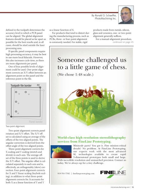
Toolpath file border<br />
F2<br />
F1<br />
Panel border<br />
Two-point alignment.<br />
Two-point alignment corrects panel<br />
rotation and X/Y offset. The X/Y offset<br />
is calculated using an average of the<br />
offsets of the two aligned points. The<br />
angular correction is derived from the<br />
offset angle of the two aligned points.<br />
Three-point alignment corrects for<br />
X scaling and Y scaling (stretch and<br />
shrink) in each axis. The average offset<br />
of the three points is used <strong>to</strong> derive<br />
the X/Y offset. The angular offset is calculated<br />
separately in each axis and is,<br />
effectively, an orthogonality (skew) correction.<br />
Four-point alignment corrects<br />
for X and Y linear scaling (keyhole scaling),<br />
in addition <strong>to</strong> what three-point<br />
alignment corrects for. It accounts for<br />
both X <strong>as</strong> a linear function of Y and Y<br />
World-cl<strong>as</strong>s high resolution stereolithography<br />
services from FineLine Pro<strong>to</strong>typing.<br />
Miniscule parts? You got it. Fine mission-critical<br />
details? No problem. At FineLine Pro<strong>to</strong>typing,<br />
our experts work with the most advanced<br />
SL technologies available <strong>to</strong> create rapid<br />
3-dimensional pro<strong>to</strong>types both small and large.<br />
With incredible resolution and unmatched precision. Contact us<br />
<strong>to</strong>day. We’re always up for a tiny challenge.<br />
919-781-7702 | finelinepro<strong>to</strong>typing.com<br />
micromanufacturing.com | 15