Capacitive Micromachined Ultrasonic Transducer Arrays For ...
Capacitive Micromachined Ultrasonic Transducer Arrays For ...
Capacitive Micromachined Ultrasonic Transducer Arrays For ...

Create successful ePaper yourself
Turn your PDF publications into a flip-book with our unique Google optimized e-Paper software.
<strong>Capacitive</strong> <strong>Micromachined</strong> <strong>Ultrasonic</strong> <strong>Transducer</strong> <strong>Arrays</strong> <strong>For</strong> Medical Imaging:<br />
Experimental Results<br />
U. Demirci*, Ö. Oralkan, J. A. Johnson, A. S. Ergun, M. Karaman, B. T. Khuri-Yakub<br />
E. L. Ginzton Laboratory, Stanford University, Stanford, CA 94305-4085<br />
Abstract—<strong>Capacitive</strong> micromachined ultrasonic transducer<br />
(cMUT) arrays provide broad bandwidth, high<br />
sensitivity, low mechanical impedance, and potential for<br />
electronic integration, and thus are promising for medical<br />
imaging applications. We have designed and fabricated<br />
1D and 2D cMUT arrays of various sizes using<br />
standard integrated circuit fabrication processes. We<br />
improved the device parameters for medical imaging<br />
applications to achieve fully functional 64- and 128-<br />
element linear 1D cMUT arrays. We have also built a<br />
computer controlled experimental setup for collecting<br />
pulse-echo data from the test phantoms using cMUT<br />
arrays. In this paper the design and optimization of the<br />
immersion cMUTs for medical imaging system are discussed,<br />
and the phased array B-scan sector images<br />
taken by 1D cMUT arrays are presented.<br />
I. INTRODUCTION<br />
Piezoelectric devices have been the primary<br />
transducer technology in medical ultrasonic imaging.<br />
In the last decade, cMUTs have emerged<br />
as an alternative to conventional piezoelectric<br />
transducers [1, 2]. The main benefit of cMUTs is<br />
that they have low self-noise, broad bandwidth<br />
and high sensitivity. [3]. In addition, they are<br />
easy to fabricate in 1D and 2D arrays using<br />
standard integrated circuit fabric ation processes.<br />
The first imaging results shown by using<br />
cMUTs were proof-of-concept experiments<br />
based on receiving from an active source placed<br />
at a distance in a tank of oil [4]. The first pulseecho<br />
imaging using a 1D cMUT array was demonstrated<br />
in [5]. The array used in the first pulseecho<br />
B-scan sector imaging had high collapse<br />
voltages around 50V, which caused problems in<br />
terms of switching with relays, and automated<br />
control of imaging. Only a 16-element portion of<br />
a 64-element array was used due to the problems<br />
in the process yield.<br />
Recently, with improvements in our process<br />
flow to achieve 100% yield, we were able to<br />
fabricate fully functional 64- and 128-element<br />
immersion 1D cMUT arrays. We also built a<br />
computer-controlled automated experimental<br />
* utkan@stanford.edu<br />
setup to collect pulse-echo data. In this paper,<br />
we present the first pulse-echo B-scan sector<br />
images of a wire phantom obtained with 64 element<br />
1D cMUT arrays.<br />
II. CMUT FABRICATION<br />
A cMUT cell is basically a membrane suspended<br />
over a very highly doped silicon substrate. The<br />
topside of the membrane is coated with an ele c-<br />
trode that creates a capacitance to the ground. In<br />
order to operate the cMUT, a DC voltage is applied<br />
to pull the membrane down close to the<br />
bottom electrode by the effect of the Coulomb<br />
attraction force. If an AC voltage is applied on<br />
top of the DC voltage, the membrane starts to<br />
vibrate and generates a pressure wave in the surrounding<br />
medium. On the other hand, when an<br />
ultrasound signal hits the surface of the DC biased<br />
membrane, a current is generated in the<br />
receiving circuitry due to the changing capacitance.<br />
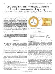
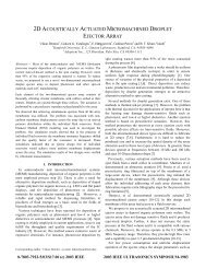
A 1D array is composed of 64 elements next<br />
to each other as seen in Figure 1. Each element<br />
has membranes connected in parallel<br />
as shown in Figure 2.<br />
The fabrication process involves surface micromachining<br />
and is compatible with standard IC<br />
manufacturing technology. The processing starts<br />
with heavily doping a 4” n-type (100) silicon<br />
wafer with phosphorus. The purpose is to<br />
achieve good conductivity at the surface that<br />
forms the bottom electrode. Then, a thin layer of<br />
LPCVD SiN x is deposited as an etch stop in the<br />
sacrificial etching with KOH. Poly-silicon is<br />
deposited and patterned in order to form the sacrificial<br />
layer that defines the active area. A second<br />
layer of LPVCD SiN x is then deposited<br />
which later becomes the membrane. The critical<br />
point here is to achieve a low-tensile stress in the<br />
membrane. Etch holes are dry-etched to allow a<br />
path for the KOH to etch the sacrificial polysilicon<br />
layer. The membranes are released, when<br />
the sacrificial layer is removed [8]. The vacuum
membranes break, since all the membranes are<br />
isolated from each other.<br />
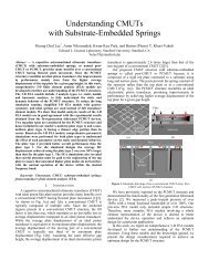
Figure 1: 128-Element 1D cMUT array mounte d<br />
on the fanout board.<br />
250 um<br />
Figure 2: 1-D array elements.<br />
sealing is done by additional SiN x deposition.<br />
Finally, aluminum is sputtered and wet etch<br />
patterned to act as the top electrode.<br />
III. PROCESS IMPROVEMENTS<br />
The transducer geometry is significant for the<br />
determination of the transducer characteristics.<br />
The process capabilities and device performance<br />
requirements determine the device dimensions.<br />
The sealing is required because the water fills in<br />
the gaps under the membrane and increases the<br />
loss for the immersion devices while the membrane<br />
is moving. The gap thickness is dependent<br />
on the sealing mechanism because the SiN x has<br />
a very low sticking coefficient and 1/3 of the<br />
deposited SiN x ends up under the membrane<br />
while sealing. To achieve a better control over<br />
the gap and membrane thickness, we separated<br />
the etch channel and active area definitions. In<br />
this way, we can make the etch channels as thin<br />
as possible independent of the gap thickness as<br />
shown in Fig. 3. This method has two advantages:<br />
the etch channels seal much faster, and<br />
very little SiN x gets inside the gap. The other<br />
important aspect of this approach is that the array<br />
element still works even if some of the<br />
In the previous process the gap thickness was<br />
initially chosen to be 3000 Å, and 6000 Å of<br />
SiN x was necessary to seal the membranes.<br />
2000 Å of SiN x was getting deposited inside the<br />
gap decreasing the vacuum gap thickness to<br />
1000 Å. In the recent process, the initial gap<br />
thickness was 1500 Å before sealing. The lowest<br />
channel height achieved is 500 Å using the new<br />
method. In this new process,1000 Å of SiN x are<br />
needed to seal the membranes. Only 300 Å of<br />
nitride goes under the membrane thus giving us<br />
a better control over the membrane and gap<br />
thickness.<br />
Sealing increases the membrane thickness as<br />
much as the total deposited SiN x . In order to<br />
bring the membrane back to the aimed design<br />
thickness, a dry etch back is used. This step was<br />
very critical due to the fact that over-etching of<br />
the membranes resulted in pinholes on the membrane<br />
surface causing malfunctioning devices. In<br />
the current process the membrane is deposited as<br />
thin as possible for most efficient operation and<br />
low DC bias. However, the membrane is still<br />
thick enough to avoid collapse, and to provide<br />
enough stress for successful release after sacrificial<br />
layer removal. The etch-back step is no<br />
longer necessary after the sealing.<br />
The transducer metallization has two main functions:<br />
forming the circular metal plate at the top<br />
of the membrane, and interconnecting adjacent<br />
cells together. Smaller metallization area is always<br />
preferred due to lower parasitic capacitance.<br />
Channel definition<br />
Figure 3: Two step active area definition.
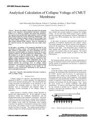
SWITCHING BOARD<br />
BIAS BORD<br />
FAN-OUT BOARD<br />
cMUT ARRAY<br />
PHANTOM<br />
WATER TANK<br />
ADC CARD<br />
SOFTWARE<br />
Figure 4: The experimental setup.<br />
The design parameters are set according to a<br />
computer simulation that employs the equivalent<br />
circuit models explained in [6], [7]. The design<br />
parameters are a membrane radius of 18 µm, a<br />
gap thickness of 0.12 µm, a membrane thickness<br />
of 0.88 µm, and an insulator thickness of 0.2<br />
µm. The device has a resonant frequency of 12<br />
MHz in air. The element pitch is 250 µm, which<br />
is suitable for imaging at 3 MHz. Although the<br />
devices resonate at 12 MHz in air, the low mechanical<br />
impedance of the cMUTs is damped<br />
when immersed in water, yielding around 100%<br />
bandwidth.<br />
IV. PULSE-ECHO IMAGING<br />
PC<br />
The experimental setup is shown in Fig. 4. It<br />
includes a fan-out board for the cMUT array, a<br />
biasing board, and an RF board that has TX/RX<br />
switches, front-end amplifiers and multiplexers<br />
to reduce the number of channels that go to the<br />
A/D card installed on the controlling computer.<br />
The phantom consists of uniformly spaced, parallel<br />
stainless steel wires submerged in oil. The<br />
wires are arranged in a diagonal fashion in order<br />
to measure the point-spread functions at different<br />
spatial locations. The wire phantom and the<br />
cMUT array are immersed in oil. All the<br />
switching among the array elements is done by<br />
computer software.<br />
A sample of the echo signals coming from the<br />
phantom wires is shown in Fig. 5. There are a<br />
total of 7 wires visible in the received echo signal.<br />
The applied signal is a unipolar pulse with a<br />
width of 100 ns width resulting in a broadband<br />
signal. Therefore, we can determine the two-way<br />
frequency response of our cMUT array elements<br />
by looking at the Fourier Transform one of the<br />
echo signals. A sample echo signal and its Fourier<br />
Transform are shown in Figs. 6 and 7, respectively.<br />
Figure 7 shows that the overall re-<br />
Received Echo Amplitude (mV)<br />
Received Echo Amplitude (mV)<br />
20<br />
15<br />
10<br />
5<br />
0<br />
-5<br />
-10<br />
-15<br />
-20<br />
Sample A-Scan<br />
50 100 150 200 250<br />
Time (us)<br />
Figure 5: A Sample A-scan acquired from the<br />
wire phantom.<br />
20<br />
15<br />
10<br />
5<br />
0<br />
-5<br />
-10<br />
-15<br />
-20<br />
115.6 115.8 116 116.2 116.4 116.6 116.8 117 117.2<br />
Normalized Magnitude (dB)<br />
Impulse Response<br />
Time (us)<br />
Figure 6: Pulse-echo Impulse response of the<br />
cMUT array element.<br />
0<br />
-1<br />
-2<br />
-3<br />
-4<br />
-5<br />
-6<br />
Frequency Response<br />
-7<br />
1.5 2 2.5 3 3.5 4 4.5<br />
Frequency (MHz)<br />
Figure 7: Pulse-echo Frequency response of<br />
the cMUT array element.
sponse has a fractional bandwidth of 85%, a<br />
promising result for medical imaging. However,<br />
the actual bandwidth of the cMUT is even<br />
larger. Taking the diffraction and medium losses<br />
sampling criteria is not violated for the highest<br />
frequency components in the transducer response.<br />
Crosstalk between the array elements is<br />
observed which is due to Lamb waves propagating<br />
in the silicon wafer, and Stonley waves<br />
propagating at the fluid-silicon interface. The<br />
effects of cross-talk are not evident in the presented<br />
imaging results since imaging in the near<br />
field—the region most often affected by crosstalk—was<br />
not performed. Currently, reducing<br />
the crosstalk between the array elements by reevaluating<br />
the fabrication and design is subject<br />
to extensive research in the future.<br />
VI. REFERENCES<br />
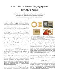
Figure 8: B-scan sector image using 64 element 1D<br />
cMUT array. Display dynamic range is 50 dB.<br />
into account, the fractional bandwidth increases<br />
to more than 100%.<br />
The image is reconstructed by employing RF<br />
beamforming and synthetic phased array approaches<br />
[9]. Dynamic focusing is employed in<br />
transmit and receive beamforming. The resulting<br />
B-scan sector image is shown in Fig. 8. The<br />
display dynamic range is 50 dB.<br />
V. CONCLUSIONS<br />
We demonstrated the successful operation of<br />
immersion cMUT arrays operating at around<br />
3MHz, an operating point suitable for medical<br />
imaging. The modifications in the process enable<br />
the fabrication of fully functional 1D and<br />
2D arrays. These arrays are then used in our experimental<br />
setup to image wire phantoms. The<br />
broad bandwidth and high sensitivity of the<br />
cMUTs are confirmed through improved axial<br />
and lateral resolution depicted by the experimental<br />
imaging results. The grating lobe artifact<br />
is observed at 90 degree angle off the first reflector.<br />
The inter-element spacing of the array is<br />
250 µm. This spacing satisfies the spatial sampling<br />
criteria for frequency components up to<br />
3 MHz. Since the cMUT array element has<br />
broadband response, frequency components<br />
higher than 3 MHz cause the grating lobe artifact<br />
mentioned above. This is not a problem for<br />
narrow band for transducers. However, cMUT<br />
arrays should be designed so that the spatial<br />
[1] M. I. Haller and B. T. Khuri-Yakub, "A surface<br />
micromachined micromachined Electrostatic<br />
electrostatic <strong>Ultrasonic</strong> ultrasonic Air air transducer,"<br />
IEEE Trans. on UFFC 43, 1-6 (January<br />
1996).<br />
[2] G. S. Kino, Acoustic Waves . Englewood Cliffs,<br />
NJ: Prentice-Hall, 1987<br />
[3] X. C. Jin, S. Calmes, C. H. Cheng, F. L. Degertekin,<br />
and B. T. Khuri-Yakub, ”<strong>Micromachined</strong><br />
capacitive ultrasonic immersion transducer<br />
array,” in <strong>Transducer</strong>s’99, Sendai, Japan,1999<br />
[4] X. C. Jin, F. L. Degertekin, S. Calmes, X. J.<br />
Zhang, I. Ladabaum, and B. T. Khuri-Yakub,<br />
"<strong>Micromachined</strong> <strong>Capacitive</strong> <strong>Transducer</strong> <strong>Arrays</strong><br />
for Medical Ultrasound Imaging," Proceedings<br />
of IEEE <strong>Ultrasonic</strong>s Symposium, Sendai, Japan,<br />
1998, pp. 1877-1880.<br />
[5] O. Oralkan , X. C. Jin, K. Kaviani, A. S. Ergun,<br />
F. L. Degertekin, M. Karaman, and B. T. Khuri-<br />
Yakub, "Initial Pulse-Echo Imaging Results with<br />
One-dimensional <strong>Capacitive</strong> <strong>Micromachined</strong><br />
<strong>Ultrasonic</strong> <strong>Transducer</strong> <strong>Arrays</strong>," Proceedings of<br />
IEEE <strong>Ultrasonic</strong>s Symposium, San Juan, Puerto<br />
Rico, 2000, pp. 959-962.<br />
[6] I. Ladabaum, X. C. Jin, H. T. Soh, F. Pierre, A.<br />
Atalar, B. T. Khuri-Yakub, ”<strong>Micromachined</strong> ultrasonic<br />
transducers : Toward robust models and<br />
immersion devices,” in <strong>Ultrasonic</strong> Symposium,<br />
San Antonio, Texas, 1996, pp. 335-338<br />
[7] W. P. Mason, Electromechanical <strong>Transducer</strong>s<br />
and wave filters. New York: Van Nostrand, 1942<br />
[8] R. M. White, R. J. Wicher, S. W. Wenzel, and E.<br />
T. Zellers “Plate mode ultrasonic oscillator sensors”<br />
IEEE Trans. Ult. Ferr. Freq. Control,<br />
vol.34, no.2, pp. 162-171, 1987<br />
[9] M. Karaman, P. -C. Li, M. O’Donnell,<br />
“Synthetic aperture imaging for small scale<br />
systems ,” IEEE Trans. on Ultrason., Ferroelect.,<br />
Freq. Contr., vol. 42, no. 3, pp 429-422, May<br />
1995