

Innovative Design of Movable Bridges - Heavy Movable Structures ...
Innovative Design of Movable Bridges - Heavy Movable Structures ...
Innovative Design of Movable Bridges - Heavy Movable Structures ...

You also want an ePaper? Increase the reach of your titles
YUMPU automatically turns print PDFs into web optimized ePapers that Google loves.
6.2 <strong>Design</strong><br />
6.2.1 Bascule Bridge<br />
The free span <strong>of</strong> 80 m and a total width <strong>of</strong> 42 m render the bascule bridge the world’s largest, Fig.<br />
6.3 and 6.4. The total length <strong>of</strong> the flaps, 54,5 m each, is divided by the axis <strong>of</strong> rotation into<br />
2 cantilevers <strong>of</strong> 42,8 m and 11,7 m.<br />
Fig. 6.3 Bascule Bridge, General Arrangement<br />
Fig. 6.4 Bascule Bridge, Cross-Section<br />
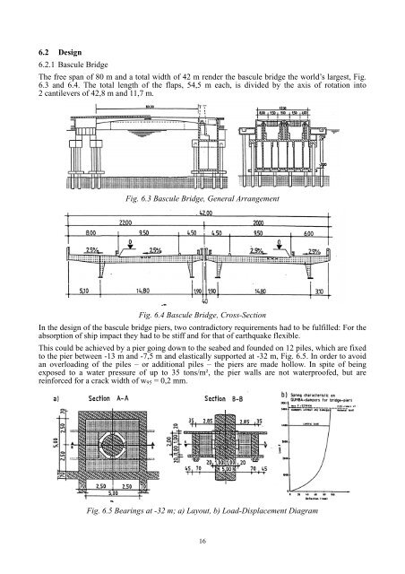
In the design <strong>of</strong> the bascule bridge piers, two contradictory requirements had to be fulfilled: For the<br />
absorption <strong>of</strong> ship impact they had to be stiff and for that <strong>of</strong> earthquake flexible.<br />
This could be achieved by a pier going down to the seabed and founded on 12 piles, which are fixed<br />
to the pier between -13 m and -7,5 m and elastically supported at -32 m, Fig. 6.5. In order to avoid<br />
an overloading <strong>of</strong> the piles – or additional piles – the piers are made hollow. In spite <strong>of</strong> being<br />
exposed to a water pressure <strong>of</strong> up to 35 tons/m², the pier walls are not waterpro<strong>of</strong>ed, but are<br />
reinforced for a crack width <strong>of</strong> w 95 = 0,2 mm.<br />
Fig. 6.5 Bearings at -32 m; a) Layout, b) Load-Displacement Diagram<br />
16


