

Innovative Design of Movable Bridges - Heavy Movable Structures ...
Innovative Design of Movable Bridges - Heavy Movable Structures ...
Innovative Design of Movable Bridges - Heavy Movable Structures ...

You also want an ePaper? Increase the reach of your titles
YUMPU automatically turns print PDFs into web optimized ePapers that Google loves.
6.2.3 Piles<br />
a) Approach <strong>Bridges</strong> and Abutments<br />
In order to reduce the masses involved into an earthquake and to save costs, the pile shafts are<br />
designed as hollow steel pipes, with an outer diameter <strong>of</strong> 2 m and a wall thickness <strong>of</strong> 20 mm only,<br />
steel quality St 52-3.<br />
b) Bascule Bridge Pier<br />
The piles <strong>of</strong> the bascule bridge pier are filled with tremie concrete B 35 and reinforced in their<br />
upper part. The design <strong>of</strong> these piles as composite columns proved that shear connectors were<br />
needed at both ends only.<br />
6.3 Special aspects <strong>of</strong> dimensioning<br />
6.3.1 Ship Impact<br />
The bridge had to be designed for the head on impact <strong>of</strong> a 8000 dwt ship sailing at 2,5 m/s. The<br />
corresponding impact force is according to the “Nordic Road Council Regulations for Ship Impact”<br />
500 · √ 500 · √8000 · 1,05 40.000 <br />
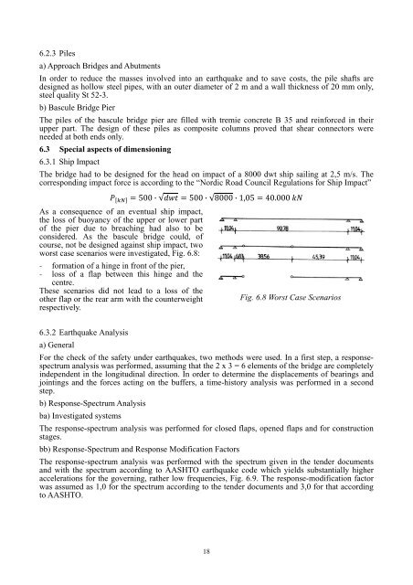
As a consequence <strong>of</strong> an eventual ship impact,<br />
the loss <strong>of</strong> buoyancy <strong>of</strong> the upper or lower part<br />
<strong>of</strong> the pier due to breaching had also to be<br />
considered. As the bascule bridge could, <strong>of</strong><br />
course, not be designed against ship impact, two<br />
worst case scenarios were investigated, Fig. 6.8:<br />
- formation <strong>of</strong> a hinge in front <strong>of</strong> the pier,<br />
- loss <strong>of</strong> a flap between this hinge and the<br />
centre.<br />
These scenarios did not lead to a loss <strong>of</strong> the<br />
other flap or the rear arm with the counterweight<br />
respectively.<br />
Fig. 6.8 Worst Case Scenarios<br />
6.3.2 Earthquake Analysis<br />
a) General<br />
For the check <strong>of</strong> the safety under earthquakes, two methods were used. In a first step, a responsespectrum<br />
analysis was performed, assuming that the 2 x 3 = 6 elements <strong>of</strong> the bridge are completely<br />
independent in the longitudinal direction. In order to determine the displacements <strong>of</strong> bearings and<br />
jointings and the forces acting on the buffers, a time-history analysis was performed in a second<br />
step.<br />
b) Response-Spectrum Analysis<br />
ba) Investigated systems<br />
The response-spectrum analysis was performed for closed flaps, opened flaps and for construction<br />
stages.<br />
bb) Response-Spectrum and Response Modification Factors<br />
The response-spectrum analysis was performed with the spectrum given in the tender documents<br />
and with the spectrum according to AASHTO earthquake code which yields substantially higher<br />
accelerations for the governing, rather low frequencies, Fig. 6.9. The response-modification factor<br />
was assumed as 1,0 for the spectrum according to the tender documents and 3,0 for that according<br />
to AASHTO.<br />
18


