

Nuts & Volts
Nuts & Volts
Nuts & Volts

Create successful ePaper yourself
Turn your PDF publications into a flip-book with our unique Google optimized e-Paper software.
transformer, then isolate the outputs<br />
for each stepper (using a diode) and<br />
filter each using a hefty capacitor (C =<br />
I out / 120 * V RIPPLE ).<br />
DOOR OPEN BUZZER<br />
QI have a Chamberlain garage<br />
door monitor that notifies<br />
me when the garage door is<br />
open or closed. When the<br />
door is closed, a coded radio signal is<br />
sent to a receiver, which displays a<br />
green LED. When the door is open, a<br />
red LED flashes once every second for<br />
as long as the door remains open. The<br />
system works great, but I would like to<br />
add a buzzer in addition to the flashing<br />
red light when the door opens.<br />
However, I don’t want the buzzer on all<br />
the time when I’m working in the<br />
garage with the door open. I want the<br />
buzzer to just initially sound for the<br />
door opening and then stop. I was<br />
thinking of using the “Adjustable<br />
Buzzer” circuit in the December ‘05<br />
column, but I’m not sure how to adapt<br />
it for my purposes. Do you have a good<br />
solution?<br />
— Christopher Rust<br />
Maple Grove, MN<br />
the garage door illuminates the green<br />
LED and effectively disables the timer<br />
— until the next open-door incident.<br />
WHICH WAY<br />
THE WIND BLOWS<br />
QI would like to build a weather<br />
vane to show the direction<br />
of the wind on a display<br />
inside my shop. Ideally, it<br />
would have LEDs to indicate at least<br />
eight wind headings. Instead of a mechanical<br />
contact at the vane, is there a<br />
simple circuit to indicate the position<br />
■ FIGURE 3<br />
24VCT<br />
17Vp-p<br />
XL = 45 ohms<br />
60mH<br />
2Vp-p<br />
Choke Input Design<br />
QUESTIONS & ANSWERS<br />
~10.5 VDC<br />
44 mVp-p<br />
Rs<br />
+<br />
+V<br />
10,000uF<br />
RL = 6 ohms<br />
of the vane? Perhaps a series of Halleffect<br />
components have to be used? I’m<br />
not sure if I understand the Hall-effect<br />
components correctly, but I’m open to<br />
anything and willing to try (read:<br />
limited electronic, self-taught, hobby<br />
education).<br />
— Larry<br />
AWelcome to the world of selftaught<br />
hobby electronics.<br />
The road is bumpy, but filled<br />
with lots of serendipity detours<br />
that lead to exciting discoveries.<br />
Let’s start with the Hall-effect.<br />
In operation, a constant bias<br />
+12V<br />
■ FIGURE 2<br />
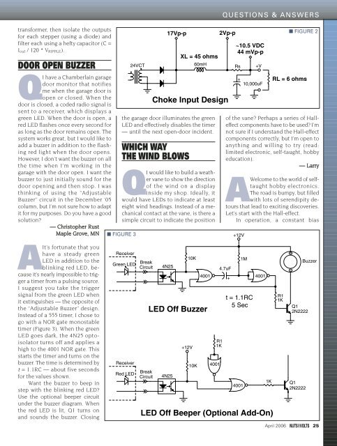
AIt’s fortunate that you<br />
have a steady green<br />
LED in addition to the<br />
blinking red LED, because<br />
it’s nearly impossible to trigger<br />
a timer from a pulsing source.<br />
I suggest you take the trigger<br />
signal from the green LED when<br />
it extinguishes — the opposite of<br />
the “Adjustable Buzzer” design.<br />
Instead of a 555 timer, I chose to<br />
go with a NOR gate monostable<br />
timer (Figure 3). When the green<br />
LED goes dark, the 4N25 optoisolator<br />
turns off and applies a<br />
high to the 4001 NOR gate. This<br />
starts the timer and turns on the<br />
buzzer. The time is determined by<br />
t = 1.1RC — about five seconds<br />
for the values shown.<br />
Want the buzzer to beep in<br />
step with the blinking red LED?<br />
Use the optional beeper circuit<br />
under the buzzer diagram. When<br />
the red LED is lit, Q1 turns on<br />
and sounds the buzzer. Closing<br />
Receiver<br />
Green LED<br />
Receiver<br />
Red LED<br />
Break<br />
Circuit<br />
Break<br />
Circuit<br />
4N25<br />
LED Off Buzzer<br />
4N25<br />
10K<br />
+12V<br />
10K<br />
4001<br />
R1<br />
1K<br />
4001<br />
4.7uF<br />
t = 1.1RC<br />
5 Sec<br />
4001<br />
LED Off Beeper (Optional Add-On)<br />
+<br />
1M<br />
4001<br />
1K<br />
R1<br />
1K<br />
+<br />
-<br />
Q1<br />
2N2222<br />
Q1<br />
2N2222<br />
Buzzer<br />
April 2006 25


