

Nuts & Volts
Nuts & Volts
Nuts & Volts

Create successful ePaper yourself
Turn your PDF publications into a flip-book with our unique Google optimized e-Paper software.
Octal Logic Probe<br />
PARTS LIST<br />
QTY. PART NO. DESCRIPTION MSRP SOURCE<br />
❑ *1 PC Board $6.50 Impossible Enterprises<br />
❑ *2 LM2901N Quad Voltage Comparator 26¢ Jameco 23296CX (or 246537CX)<br />
❑ *9 MV50G Green LED T 3/4 12¢ Jameco 176532CX<br />
❑ *9 1K 1/4W 5% Resistor 1¢ Jameco 29663CX<br />
❑ *1 SMH08/SMH17 Eight position single row header .1” 20¢/16¢ Jameco 153701CX (or 1/2 103376CX)<br />
❑ *1/4 Six foot stereo RCA audio cable $1.79 Like Jameco 228451CX (see text)<br />
❑ 1 0.1μF 25V Mylar Capacitor 11¢ Jameco 135562CX<br />
❑ 1+ 2 x 3 grid RCA block 89¢ Like Jameco 237016CX (see text)<br />
❑ 1 Full kit of all marked (*) parts $9.50 Impossible Enterprises<br />
and outputs, on both sides of the<br />
board.<br />
A couple of hints on PCB design:<br />
It is always a good idea to label either<br />
the top or bottom of the board,<br />
especially when you don't have a<br />
silkscreen. It is also a good idea to<br />
mark the board with a version number<br />
so that if you have any spares left<br />
over, you will know just which layout<br />
you have when you find them years<br />
from now — hence the "TOP" and "JSB<br />
2.0" bits of text on the top copper<br />
layer.<br />
Construction<br />
Step 1: Solder the top row of LEDs.<br />
This is the tricky part. Note how the<br />
LEDs straddle the edge of the PC<br />
board and are soldered to pads<br />
rather than inserted through holes.<br />
Though one LED lead is slightly<br />
longer than the other to indicate<br />
polarity, I find it easier to just test it<br />
with a power source and current<br />
limiting resistor, especially after having<br />
trimmed the leads and then<br />
dropping it on the bench. Get their<br />
polarity right — cathodes on the<br />
front, anodes to the back. I didn't get<br />
this right the first time and it was a<br />
chore to unsolder and reverse them.<br />
There is just enough room for each T<br />
3/4 sized LED packed edge-to-edge,<br />
so start in the middle of each group<br />
of four, then do each adjacent one,<br />
and then the final one. Position one,<br />
then note how much wire needs to<br />
be cut off. Trim it by holding it in<br />
place with your finger and tacking<br />
the front lead using the solder that's<br />
already on the board. Solder the<br />
back and then resolder the front lead<br />
(see Figure 4).<br />
Step 2: Solder all resistors and D9.<br />
Watch out for the polarity once again.<br />
Work from the middle of each quad<br />
out, like the LEDs. A pair of toe-nail<br />
clippers makes a great tool to trim the<br />
leads after soldering.<br />
Step 3: Test what you've got so far.<br />
Rig up a power supply and a couple<br />
of alligator clips. Place a 200 ohm<br />
resistor in series just to make sure<br />
any shorts won't cause trouble. Clip<br />
the plus lead to the center area<br />
between the LED groups and the<br />
negative lead to one end of a<br />
voltmeter probe. Touch the probe to<br />
ground; the pilot light should light.<br />
Touch the probe to each of the eight<br />
resistors; exactly one LED should<br />
light. If one does not, check the<br />
solder joints and the LED polarity. If<br />
more than one does, look for solder<br />
bridges (see Figure 5).<br />
Step 4: Cut and attach the header.<br />
Not too close — remember to leave<br />
a little room for the IC pins. Use<br />
'gator clips to hold the edges and<br />
solder some center pins, then<br />
remove the clips and finish the job<br />
(see Figure 6).<br />
Step 5: It’s time to add the ICs. Make<br />
sure that pin 1 is nearest to the<br />
LEDs. Alternate soldering between<br />
the two ICs to give them a chance<br />
to cool down.<br />
Step 6: Strip and solder the power<br />
cable to the designated holes. The<br />
center conductor should be +V; the<br />
hole between the LEDs. The shield<br />
goes in the hole on the left just below<br />
the LEDs. Insert both from the front,<br />
then bend the cable around to the<br />
back and use a blob of hot melt glue<br />
to anchor it to the back of the board<br />
(see Figure 7).<br />
Step 7: Build your power distribution<br />
panel by connecting the center<br />
terminals of all the RCA jacks<br />
together. Typically, all blocks have the<br />
ground (outer) connector already in<br />
common. Add a cable from it to your<br />
power supply. Keep the center lead<br />
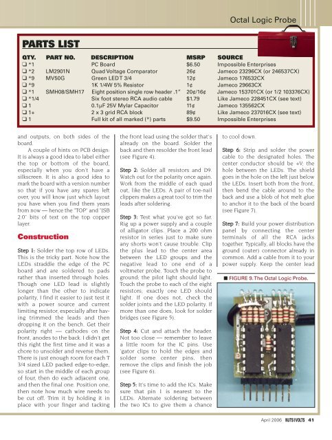
■ FIGURE 9. The Octal Logic Probe.<br />
April 2006 41


