

Nuts & Volts
Nuts & Volts
Nuts & Volts

You also want an ePaper? Increase the reach of your titles
YUMPU automatically turns print PDFs into web optimized ePapers that Google loves.
QUESTIONS & ANSWERS<br />
hand, has an<br />
additional gate connected<br />
to the anode<br />
side of the device.<br />
When a negative<br />
voltage is applied to<br />
the anode gate (or<br />
the anode is shorted<br />
to the cathode),<br />
it can turn off the<br />
SCS through forced<br />
commutation. A<br />
typical SCS circuit is<br />
shown in Figure 7.<br />
The four-layer<br />
SCS structure is<br />
equivalent to an<br />
NPN and a PNP<br />
■ FIGURE 6<br />
From<br />
Vane<br />
Sensors<br />
In0<br />
In1<br />
In2<br />
In3<br />
In4<br />
In5<br />
In6<br />
In7<br />
transistor configured in a forced<br />
feedback situation. When the ON pushbutton<br />
is pressed, voltage is applied<br />
between the cathode gate and the<br />
cathode, forward-biasing the lower<br />
transistor and turning it on. This, in<br />
turn, causes current to flow through the<br />
upper transistor’s base junction via R2<br />
and turn it on. The SCS is now locked<br />
on, causing the motor to start and run<br />
— even after the ON switch is opened.<br />
Pressing the OFF push-button<br />
shorts the anode terminal to the cathode.<br />
This causes the upper transistor<br />
to lose its emitter current and break<br />
the current flow to the base of the<br />
lower transistor. The SCS now loses<br />
its lock on the anode/cathode current<br />
flow and turns off the motor. The SCS<br />
will remain in the off condition until<br />
the ON button is again pressed.<br />
SCS devices are not as widely used<br />
as once seemed possible. Their low use<br />
is likely due to the peak current that<br />
+5V<br />
Transmitter<br />
1K<br />
Weather Vane 3-wire Transmitter/Receiver<br />
could be reliably turned off by the<br />
anode gate. Consequently, they are<br />
hard to find and often expensive.<br />
However, I was able to locate a small<br />
cache of the 3N86 at a reasonable price<br />
from Wholesale Electronics (www.weis<br />
d.com/store2/JSH3N86.html). It’s rated<br />
65 volts at 200 mA, which will limit your<br />
experiments and applications.<br />
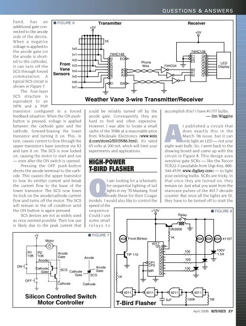
HIGH-POWER<br />
T-BIRD FLASHER<br />
QI am looking for a schematic<br />
for sequential lighting of tail<br />
lights in my ‘70 Mustang. Ford<br />
made these for their Cougar<br />
models. I would also like to control the<br />
speed of the<br />
sequence.<br />
+12V<br />
Could I use<br />
some small<br />
relays to<br />
■ FIGURE 7<br />
74HC148<br />
I0 EO<br />
I1<br />
I2<br />
I3<br />
I4 A0<br />
I5 A1<br />
I6 A2<br />
I7<br />
EI GS<br />
1K<br />
Front Blinker<br />
TIP 110<br />
Phone<br />
Wire<br />
4017<br />
Q5-9<br />
Q9<br />
Q8<br />
Q7<br />
Q6<br />
Q5<br />
CP1 Q4<br />
CP0 Q3<br />
Q2<br />
MR Q1<br />
Q0<br />
74HC04<br />
accomplish this? I have #1157 bulbs.<br />
— Jim Wiggins<br />
AI published a circuit that<br />
does exactly this in the<br />
March ‘06 issue, but it can<br />
only light an LED — not your<br />
eight-watt bulb. So, I went back to the<br />
drawing board and came up with the<br />
circuit in Figure 8. This design uses<br />
sensitive gate SCRs — like the Teccor<br />
TCR22-3 (available from Digi-Key; 800-<br />
344-4539; www.digikey.com) — to light<br />
your existing bulbs. SCRs are tricky, in<br />
that once they are turned on, they<br />
remain on. Just what you want from the<br />
staircase pulses of the 4017 decade<br />
counter. But once all the lights are lit,<br />
they have to be turned off to start the<br />
2N3906<br />
1K<br />
Relay<br />
100<br />
100<br />
100<br />
Receiver<br />
+5V<br />
74HC138<br />
E1 Q0<br />
E2 Q1<br />
E3 Q2<br />
Q3<br />
Q4<br />
A0 Q5<br />
A1 Q6<br />
A2 Q7<br />
LED<br />
Display<br />
■ FIGURE 8<br />
100V<br />
1.5A<br />
#1157<br />
4011<br />
4011<br />
4011<br />
4011<br />
T-Bird Flasher<br />
5uF<br />
100K<br />
1M<br />
April 2006 27


