minimoog owners manual.pdf - Synth Zone
minimoog owners manual.pdf - Synth Zone
minimoog owners manual.pdf - Synth Zone

Create successful ePaper yourself
Turn your PDF publications into a flip-book with our unique Google optimized e-Paper software.
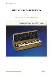
Minimoog Operation Manual<br />
the<br />
<strong>minimoog</strong><br />
synthesizer<br />
operation <strong>manual</strong><br />
MOOG MUSIC INC.<br />
Academy Street (P.O. Box 131)<br />
Williamsville, NY 14221<br />
A GUIDE TO THE OPERATION OF THE MINI MOOG MODEL D<br />
contents<br />
• introduction<br />
• basic mini moog features<br />
• audio, control, and timing signals<br />
• setting up the instrument<br />
• output section<br />
• oscillator bank<br />
• controllers<br />
• modulation mix<br />
• other controllers<br />
• mixer<br />
• modifiers<br />
• filter and filter contour<br />
• loudness contour<br />
• accessories<br />
• options<br />
• s-trigger<br />
• left-hand controller<br />
• tuning procedures<br />
http://www.oldschool-sound.com Page 1
Minimoog Operation Manual<br />
introduction<br />
An electronic music synthesizer is a musical instrument whose circuitry can be<br />
interconnected and set up in a large variety of ways to produce a broad spectrum of<br />
musical sounds. The component circuit controls and interconnections of the Mini<br />
Moog <strong>Synth</strong>esizer are arranged in a logical and convenient way which is ideal for live<br />
performance.<br />
The purpose of this <strong>manual</strong> is to acquaint you with the component circuitry of the Mini<br />
Moog and the operation of each of the controls and switches regulating the<br />
generators, modifiers, and control devices involved in the synthesizing of a musical<br />
sound. After proceeding step by step through the instructions outlined below, you<br />
should be ready to begin using your instrument creatively and efficiently.<br />
basic mini moog features<br />
The Mini Moog contains the basic components and features to be found on larger,<br />
studio-oriented synthesizers. Its five sound sources include three oscillators for the<br />
production of pitched tones, one noise source for the production of unpitched sounds,<br />
and one microphone preamplifier for the introduction of live signals. Mixer controls<br />
are available for balancing these signals.<br />
Sound modifiers include a lowpass filter and an amplifier, both of which have their<br />
own contour generators. The control devices include a 44-note keyboard for use by<br />
the right hand, and two wheel controls and two switches for use by the left hand.<br />
Provision is made at the rear of the instrument for connecting external controlling<br />
devices such as sequencers, foot pedals, and two-dimensional (joystick) controllers.<br />
These may be used to control volume, pitch, and filter characteristic. Timing signals<br />
may also be introduced to trigger the contour generators.<br />
audio, control, and timing signals<br />
Sound travels through the Mini Moog circuitry in the form of electrical signals which<br />
are called AUDIO signals. These audio signals are generated by the five sound<br />
sources, and after undergoing extensive modification emerge as the output signal. It<br />
is this signal, amplified, which is translated into sound by your speaker system.<br />
http://www.oldschool-sound.com Page 2
Minimoog Operation Manual<br />
There are two other types of signals which are not heard directly as sound, but<br />
instead are used to influence the way in which the generating and modifying circuitry<br />
performs:<br />
CONTROL signals are used to change the pitches of the oscillators, the<br />
characteristics of the filter, and the amount of amplification by the amplifier. These<br />
control signals are responsible for all of the musically significant changes and<br />
contours in the musical sounds produced by the Mini Moog.<br />
TIMING signals come from the keyboard (or from an external source) and are used to<br />
trigger, or start off, the contours which open and close the filter and amplifier. A<br />
timing signal begins whenever a key on the keyboard is depressed, and stops when<br />
all keys are released. Timing signals are used to initiate and terminate musical<br />
sounds, whereas control signals are used to shape and change these sounds while<br />
they occur.<br />
setting up the instrument<br />
Place the instrument at a convenient level for playing and secure the Front Panel in<br />
the "up" position by means of the metal bracket underneath.<br />
1. Set all switches in the off position (left-hand or bottom half depressed).<br />
2. Referring to Fig. 1, below, set all of the control knobs as indicated.<br />
3. Plug the power cord into any conventional 117 Volt A.C. outlet.<br />
4. Two 6' patch-cords are supplied with the Mini Moog. If you are using a portable,<br />
guitar-type amplifier, run the cord with the phone plug at each end from the LOW<br />
level MAIN OUTPUT jack on the rear connector strip of the Mini Moog to an input on<br />
your amplifier. If you are using a monitor amplifier, you will need to use the other<br />
cord. Plug the phone plug end into the HIGH level MAIN OUTPUT jack of the<br />
synthesizer, and run the small phono-plug at the other end into the high level input of<br />
the monitor amplifier (or into the line level input of a tape recorder).<br />
The following sections of this guide will be devoted to a systematic description of<br />
individual control functions in relation to the synthesizer's component circuits.<br />
http://www.oldschool-sound.com Page 3
Minimoog Operation Manual<br />
output section<br />
Fig. 1<br />
The Output section of the front panel includes two basic switches: the POWER<br />
switch, which turns the instrument on and off, and the MAIN OUTPUT switch, which<br />
sends the final audio signal out the MAIN OUTPUT jacks at the rear and into your<br />
amplifier. In addition, there are volume controls for the MAIN OUTPUT and<br />
HEADPHONE signals, and an A-440 switch, all of which will be described below.<br />
1. Turn on the POWER switch (P). The instrument should generally be given about<br />
ten minutes to warm up before tuning and playing. Once warmed up, there is<br />
practically no limit to the length of time it may be kept on and in use.<br />
2. Turn on switches (B) and (C) and the MAIN OUTPUT switch (M). Adjust the<br />
volume control on your amplifier so that, as you play the keyboard, fairly loud tones<br />
are heard. Further adjustments in the overall volume may be made with the MAIN<br />
OUTPUT VOLUME control (26)<br />
3. Briefly turn on the A-440 switch (Q). This signal will be used for tuning the<br />
instrument, and is not used during actual performance. The tuning procedure will be<br />
described in the controllers section, step 11.<br />
4. A separate output is available for headphones, in addition to the MAIN OUTPUT.<br />
For quiet practice, or for tuning up prior to performance, the MAIN OUTPUT switch<br />
may be turned off, so that the audio signal is not fed into the amplifier. A pair of low<br />
impedance headphones with a stereo plug may be plugged into the jack labelled<br />
PHONES (N). The HEADPHONE VOLUME control (27) is then used to regulate the<br />
volume of the headphone signal.<br />
http://www.oldschool-sound.com Page 4
Minimoog Operation Manual<br />
Front Panel Diagram<br />
oscillator bank<br />
This group of circuits contains three separate and independent oscillators. Each<br />
oscillator produces a waveform which repeats regularly, thereby giving rise to a tone<br />
of definite pitch. The audio signal outputs of the three oscillators are activated by<br />
turning on mixer switches (C), (E), and (G). Since switch (C) is now on, we are<br />
hearing the output of oscillator 1, which is the top row of controls (4, 5, and 12).<br />
1. The RANGE switch (4) determines the pitch range in which the oscillator functions.<br />
Press down a key in the middle of the keyboard, and turn the RANGE switch through<br />
its 6 positions. You will hear that all positions except the lowest are separated by one<br />
octave. The LO position produces sub-audio clicks which may be used for rhythmic<br />
effect. Return the switch to its 8´ position.<br />
2. The WAVEFORM switch (5) selects one of six waveforms, each of which has a<br />
different overtone spectrum, and therefore produces a different basic tone quality.<br />
From left to right, the available waveforms are: triangular, sawtooth-triangular,<br />
sawtooth, square, wide rectangular, and narrow rectangular. (Oscillator 3 substitutes<br />
a reverse sawtooth for the sawtooth-triangular.)<br />
Hold a key down and run the WAVEFORM switch through its positions, noticing how<br />
the tone quality changes. The triangular waveform has the least harmonic content;<br />
the narrow rectangular has the most. Generally your ear will be your best guide in<br />
deciding which waveform to use for a particular quality.<br />
http://www.oldschool-sound.com Page 5
Minimoog Operation Manual<br />
3. The VOLUME control (12) adjusts the amount of Oscillator 1 signal which is fed to<br />
the mixer, while switch (C) instantly turns the oscillator on or off. Oscillators 2 and 3<br />
may be heard by turning on switches (E) and (G) respectively, and their relative<br />
volumes may be adjusted with VOLUME controls (13) and (14).<br />
4. FREQUENCY controls (7 and 10) are found only on Oscillators 2 and 3. These<br />
controls raise or lower the pitch of their oscillator by as much as a major sixth with<br />
respect to Oscillator 1. To hear this, turn on switches (C) and (E), turn off (G), and<br />
depress a key. Adjust control (7) until the pitches of Oscillators 1 and 2 are nearly in<br />
unison. As you move up and down the keyboard, the pitches of the two oscillators will<br />
move together. Now turn control (7) clockwise while depressing a key, until a perfect<br />
fifth is made. Once again, this interval will remain constant as you play different notes<br />
on the keyboard. Any intervals within the range of the oscillators may be set up<br />
simply by setting the RANGE switches and FREQUENCY controls appropriately.<br />
5. By turning off the OSCILLATOR 3 CONTROL switch (B), Oscillator 3 may be<br />
disconnected from the control of the keyboard. To observe this, turn off switches (B),<br />
(C), and (E), and turn on switch (G). The pitch of the oscillator will not change as<br />
different keys are struck. You will also observe that Oscillator 3's FREQUENCY<br />
control has a much wider range when switch (B) is off. If you hold down one key and<br />
turn control (10) through its range, you will hear a frequency sweep of 6 octaves<br />
rather than one octave.<br />
controllers<br />
This section will demonstrate the use of the controls located to the left of the<br />
Oscillator Bank (used in tuning and setting up a sound), as well as the keyboard and<br />
the <strong>manual</strong> controls on the panel to its left (used during performance). All of these<br />
controls have an effect on the oscillators' pitches, while the Modulation Mix and<br />
keyboard may also be used to control the filter.<br />
modulation mix<br />
Oscillator 3, unlike Oscillators 1 and 2, is available as a control signal in addition to<br />
functioning as an audio signal. As a control signal, it may be mixed with the output of<br />
the Noise Source using the MODULATION MIX control (3) and introduced whenever<br />
the performer wishes, using the MODULATION wheel (29). The procedure described<br />
below will familiarize you with the use of the Modulation Mix in controlling the pitch of<br />
Oscillator 1:<br />
http://www.oldschool-sound.com Page 6
Minimoog Operation Manual<br />
1. Turn off switch (B), so that the pitch of Oscillator 3 is not affected by the keyboard.<br />
2. Turn off switch (G) and turn on switch (C). Now you are hearing Oscillator 1, but<br />
not Oscillator 3, when a key is depressed.<br />
3. Set Oscillator 3's RANGE switch (9) to the LO position, its FREQUENCY control<br />
(10) to mid (0) position, and its WAVEFORM switch (11) to the triangular (extreme<br />
left) setting. This produces a very low frequency triangular waveform which oscillates<br />
only a few times a second.<br />
4. Set the MODULATION MIX control to 0, so that its signal is that of Oscillator 3.<br />
Turn on the OSCILLATOR MODULATION SWITCH (A). This switch directs the<br />
Modulation Mix signal to control the oscillators' pitches.<br />
5. The slowly varying output voltage of Oscillator 3 is now going through the<br />
MODULATION wheel (29) at the left of the keyboard, and from there may be applied<br />
to periodically change the oscillators' pitches (we will hear its effect on Oscillator 1).<br />
The MODULATION wheel is in effect a level control for the Modulation Mix. Slowly<br />
move the MODULATION wheel back and forth with your left hand while holding down<br />
a key with your right hand. The position of the Modulation wheel will determine the<br />
amount of variation you hear in the pitch of Oscillator 1.<br />
6. Change the setting of Oscillator 3's FREQUENCY control and notice the resulting<br />
increase and decrease in the speed of the modulation<br />
7. Change the setting of Oscillator 3's WAVEFORM switch and you will notice the<br />
change in the shape of the modulation. You should actually be able to hear the<br />
contours of the different waveforms the alternation of high and low tones in the<br />
square wave, the repeated upward glissandi of the sawtooth, etc.<br />
8. The setting of the MODULATION MIX control determines the proportions of the<br />
mixture of Oscillator 3 and Noise Source. As you slowly turn this control clockwise,<br />
you will hear less periodic modulation and more random modulation.<br />
9. Before continuing, defeat the oscillator modulation by turning off switch (A).<br />
other controllers<br />
10. The PITCH wheel (28), located next to the MODULATION wheel to the left of the<br />
keyboard, is used to bend the pitch determined by the keyboard (as much as half an<br />
octave up or down) when the performer wishes to introduce expressive nuances to<br />
individual notes during performance. Depress a key, and move the PITCH wheel<br />
http://www.oldschool-sound.com Page 7
Minimoog Operation Manual<br />
back and forth with your left hand. Notice that you can reset the control by feel a<br />
detent mechanism holds it in its normal center position.<br />
11. The TUNE control (1) is used to tune up the Mini Moog oscillators to the pitch of<br />
the ensemble in which it is being used, or to its A-440 reference tone. Check to see<br />
that switch (C) is on, and notice that, when a key is depressed, the pitch moves up<br />
and down by a few tones as the TUNE control is turned through its range. Make sure<br />
the PITCH wheel is in its center position, and turn on the A-440 switch (Q). Depress<br />
an A key on the keyboard, and adjust the TUNE control so that the two A's are in<br />
tune with each other. Turn off the A-440. The other two oscillators may now be tuned<br />
to Oscillator 1 using their FREQUENCY controls.<br />
12. The GLIDE control (2) regulates the amount of portamento, or glide, heard<br />
between pitches as first one key and then another is depressed. This control is<br />
activated by turning on the GLIDE switch (R). Setting the GLIDE control at various<br />
levels, play a scale or arpeggio, first with the GLIDE switch on, then using the switch<br />
to introduce glide selectively between certain notes only. Notice that the further to the<br />
right control (2) is set, the longer it will take a tone to move from one pitch to the next.<br />
13. Finally, the KEYBOARD itself functions as a controller. It produces a control<br />
signal which varies according to the position of the key struck. If more than one key is<br />
held down, only the lowest one has effect. The control output of the KEYBOARD is<br />
permanently connected to Oscillators 1 and 2. Switch (B) couples it to Oscillator 3.<br />
Switches (K) and (L) couple it to the filter, and are discussed in the modifiers section,<br />
step 8. The KEYBOARD also produces a timing signal each time a key is depressed.<br />
This will be discussed in the modifiers section in connection with filter and loudness<br />
contour controls.<br />
mixer<br />
Audio signals produced by the three oscillators, noise source, and microphone<br />
preamplifier are combined and balanced by the Mixer section's switches and volume<br />
controls. It is this composite signal, the output of the mixer, which is then modified by<br />
the filter and loudness contour controls and appears as the audio output signal of the<br />
Mini Moog.<br />
1. The OSCILLATOR VOLUME controls (12, 13, and 14) are used to regulate the<br />
relative levels of the audio signals produced by the three oscillators. Switches (C),<br />
http://www.oldschool-sound.com Page 8
Minimoog Operation Manual<br />
(E), and (G) instantly turn the individual audio signals on and off. Switch (G) does not<br />
affect the control signal produced by Oscillator 3 via the Modulation Mix. The<br />
operation of these controls and switches has been discussed earlier.<br />
2. The EXTERNAL INPUT VOLUME control (15) is connected to a microphone<br />
preamplifier. The input to this preamplifier is the phone jack on the rear panel labelled<br />
EXT. SIGNAL INPUT. Any sort of high impedance microphone signal or sound<br />
source may be fed into this input. This includes guitar microphone, voice microphone,<br />
wind instrument microphone, tape recorder output, radio, etc. Control (15) is adjusted<br />
so that the OVERLOAD light blinks on and off occasionally when loud sounds come<br />
through the external input. Switch (D) feeds this source into the mixer.<br />
3. The NOISE VOLUME control (16) regulates the level of the signal produced by the<br />
Noise Source. This source generates a random waveform producing pitch-less<br />
sound. Two colors of noise are available white, or high-pitched, and pink, or lowpitched.<br />
These are selected by the Noise Quality switch (H), labelled WHITE/PINK.<br />
As an audio signal, the Noise Source may be fed into the mixer by turning on switch<br />
(F). As a control signal, it is available through the Modulation Mix, as described in the<br />
controllers section.<br />
modifiers<br />
The Modifiers section of the front panel features controls for the two sound modifiers,<br />
the Filter and the Loudness Contour, which respectively shape the overtone content<br />
and loudness/time contour of the audio signal as it passes through the modifying<br />
circuitry from the mixer. In order to hear the effect of these controls, begin by setting<br />
the controls in the oscillator and mixer sections as follows:<br />
Control<br />
Setting<br />
Oscillator MODULATION off<br />
SWITCH (A)<br />
Oscillator 1 RANGE (4) 16´<br />
Oscillator 1 WAVEFORM (5) narrow rectangular (extreme right)<br />
Oscillator 1 VOLUME (12) 7<br />
Oscillator 1 MIXER switch (C) on<br />
Other mixer switches (D, E, F, G) off<br />
Switches (J) (K) (L)<br />
off<br />
The controls on the Modifiers section should still be set as shown in Fig. 1 of the<br />
section titled setting up the instrument .<br />
http://www.oldschool-sound.com Page 9
Minimoog Operation Manual<br />
filter and filter contour<br />
The Mini Moog features a wide-range lowpass filter. This filter attenuates, or cuts out,<br />
those frequency components of an audio signal which lie above a variable cutoff<br />
frequency, while passing those components which lie below it.<br />
1. The CUTOFF FREQUENCY control (17) is used to set the filter's cutoff frequency.<br />
Hold down a key and turn this control first clockwise, then counter-clockwise. You will<br />
hear the tone become more shrill and then more muted, as the higher overtones are<br />
first allowed to pass and then attenuated. If control (17) is moved all the way to the<br />
left, the entire signal will be cut out.<br />
2. The AMOUNT OF CONTOUR control (19) determines the amount of filter contour<br />
applied to the filter's cutoff frequency. Each time a key is depressed, a contour<br />
generator attached to the filter is actuated, and sends a control signal to the filter.<br />
The control signal rises at one rate, then falls at a second rate, and finally levels off at<br />
a certain level. This results in a corresponding rise, fall, and leveling off of the filter<br />
cutoff frequency, which we call the filter contour.<br />
Set the CUTOFF FREQUENCY to -2 and repeatedly depress and hold down a key<br />
while setting the AMOUNT OF CONTOUR at various levels. The more this control is<br />
turned up, the greater will be the increase and decrease in the brightness of each<br />
note. Controls (17) and (19) have an additive effect on the cutoff frequency.<br />
3. The ATTACK TIME control (20) determines the duration of the initial segment of<br />
the filter contour. The initial rise of the filter cutoff frequency can be as short as 10<br />
milliseconds or as long as 10 seconds. (The frequency at which the contour begins is<br />
determined by control (17), while the peak which it reaches is determined by controls<br />
(17) and (19) combined.) Repeatedly depress a key while varying the setting of the<br />
ATTACK TIME control from left to right. You will hear the brightness of the note<br />
increase sharply at first, and then more gradually as the attack time increases.<br />
4. The DECAY TIME control (21) determines the duration of the second segment of<br />
the contour, the fall from the initial peak to the sustain level. The range of this control<br />
is about the same as that of the previous control. Set the DECAY TIME control at<br />
various levels moving slowly from left to right, while repeatedly depressing a key. At<br />
first you will hear the brightness drop sharply after the initial attack; the drop will<br />
become more gradual as the decay time increases.<br />
http://www.oldschool-sound.com Page 10
Minimoog Operation Manual<br />
5. The SUSTAIN LEVEL control (22) determines the frequency at which the contour<br />
levels off after the initial rise and fall. The frequency of the sustain level can be as<br />
high as the initial peak, in which case there is no decay after the initial rise, or it can<br />
be as low as the frequency at which the contour began. To hear this most effectively,<br />
set the filter controls for CUTOFF FREQUENCY of -2, high AMOUNT OF<br />
CONTOUR, and medium DECAY TIME. Now repeatedly depress and hold down a<br />
key while setting control (22) at various levels. Set at 0, the contour decay effectively<br />
wipes out the signal; set in the middle, the brightness levels off at a frequency<br />
somewhere below the initial peak, and set at 10, the brightness of the note rises to<br />
an initial peak and remains there.<br />
6. The EMPHASIS control (18) introduces a sharp resonance in the response of the<br />
filter at the cutoff frequency. The effect of this control can be heard very easily. To<br />
observe it, turn the AMOUNT OF CONTOUR fully to the left to shut off the contour<br />
signal, and turn the EMPHASIS control to 7. Depress a key, and turn the CUTOFF<br />
FREQUENCY control slowly throughout its range. You should hear the individual<br />
overtones of the oscillator waveform being emphasized one by one as the resonance<br />
passes over them. Now set the CUTOFF FREQUENCY to about -2, turn the<br />
AMOUNT OF CONTOUR all the way up, and repeatedly hold down a key while<br />
changing the settings of controls (20), (21), and (22). Notice how the filter contour is<br />
now heard as a sweep of the overtone series when (20) and (21) are turned up to<br />
about 7 seconds and (22) is set low.<br />
We have seen how the filter cutoff frequency may be controlled <strong>manual</strong>ly and using<br />
the filter contour controls. These are in addition to other means of controlling the<br />
filter.<br />
7. The MODULATION MIX (3) of Oscillator 3 and the Noise Source may be used to<br />
modulate the filter cutoff frequency in exactly the same way it is employed to<br />
modulate the pitches of the oscillators. To direct the Modulation Mix to the filter, the<br />
FILTER MODULATION switch (J) must be turned on. Then the MODULATION wheel<br />
(29) can be moved forward with the left hand to introduce the desired amount of<br />
modulation as the keyboard is played with the right hand. To test this, turn (18) and<br />
(19) all the way down and set (17) to about 1 or 2. Make sure that the Oscillator<br />
Modulation switch (A) and Osc. 3 Control Switch (B) are off, and turn on switch (J).<br />
http://www.oldschool-sound.com Page 11
Minimoog Operation Manual<br />
Set the MODULATION MIX control all the way to the left. Oscillator 3's RANGE<br />
switch should be set to LO. You will observe as you did when applying the<br />
Modulation Mix to the oscillators that the modulation contour depends on the settings<br />
of the FREQUENCY and WAVEFORM controls of Oscillator 3. A more complex<br />
sound can be made by adding the effects of controls (18) and (19).<br />
8. The two KEYBOARD CONTROL switches (K) and (L) apply the control signal<br />
produced by the keyboard to move the filter cutoff frequency up and down. This is<br />
important in setting up a sound, for if there is no keyboard control of the filter, the<br />
higher notes on the keyboard will sound duller than the lower ones, having more of<br />
their overtones attenuated. To observe the effect of these switches, turn off Oscillator<br />
1 (C) and the Filter Modulation switch (J), and set control (17) to 0. Turn on the<br />
NOISE SOURCE (F) and set the Noise Quality switch (H) to WHITE. This feeds white<br />
noise through filter and amplifier. Turn on switches (K) and (L) and play up and down<br />
the keyboard. You will hear the brightness of the white noise increase and decrease<br />
according to the position of the key which you have depressed. Switch (K) couples a<br />
small amount of keyboard control; switch (L) couples a larger amount. When (K) and<br />
(L) are both on, the filter cutoff frequency moves in full response to the keyboard<br />
control signal.<br />
NOTE:<br />
When the EMPHASIS control is set to 10, the filter breaks into oscillation, and<br />
produces a pure sine wave tone. It thus is available as a sixth sound source within<br />
the Mini Moog. The pitch of this additional oscillator may be controlled by the five<br />
other controls on the keyboard. The sixth sound source may be used alone or mixed<br />
with the other sound sources to achieve a variety of complex effects.<br />
To hear the sixth sound source alone, set up the instrument as follows:<br />
Control<br />
Setting<br />
All Mixer switches (C,D,E,F,G) off<br />
Filter Modulation switch (J) off<br />
Keyboard Control switches (K & L) on<br />
Cutoff Frequency (17) -2<br />
Emphasis (18) 10<br />
Amount of Contour (19) 0<br />
Now hold down or repeatedly strike a key, while experimenting with the following<br />
means of controlling pitch:<br />
http://www.oldschool-sound.com Page 12
Minimoog Operation Manual<br />
1. Manually, using CUTOFF FREQUENCY control.<br />
2. Using Filter Contour Controls (19-22).<br />
3. Using the Modulation Mix (see step 7 above).<br />
4. Using the Keyboard. Differently tempered scales will result from different settings of<br />
(K) and (L).<br />
loudness contour<br />
The volume of the audio signal which passes through the Modifiers section of the<br />
Mini Moog is contoured by the Loudness Contour controls. These controls are<br />
connected to a contour generator which supplies a control signal to the amplifier. Like<br />
the filter contour signal, the loudness contour signal is composed of three segments<br />
initial rise, decay, and sustain level. Each time a key is struck, the contour generator<br />
is activated, and a note is shaped according to the settings of the contour controls.<br />
9. The ATTACK TIME control (23) determines the duration of the initial rise in volume<br />
to a peak. Turn off the Noise Source (F) and turn on Oscillator 1 (C). Move control<br />
(23) back and forth while repeatedly pressing down a key. Notice the different<br />
qualities which a note takes on as a sharp attack becomes a slow crescendo.<br />
10. The DECAY TIME control (24) determines the duration of the drop in volume from<br />
the initial peak to the sustain level. The decay can be sharp or gradual.<br />
11. The SUSTAIN LEVEL control (25) determines the volume level at which the<br />
contour levels off after attack and decay. Set at 0, no sustain level is heard. Set at 5,<br />
the contour diminishes to a low volume. Set at 10, no drop in volume is heard after<br />
the initial peak is reached.<br />
12. Finally, a DECAY switch (S) to the left of the keyboard allows the sound to fade<br />
out at the decay time set by control (24), rather than immediately upon release of a<br />
key. This final decay then, takes effect after the sustain level segment of the contour.<br />
To review the phases of the overall loudness contour: a key is first pressed down.<br />
This produces an initial rise in volume, a decay, and a leveling off. The key is then<br />
lifted, and the sound is either cut off immediately, or if the DECAY switch is on, fades<br />
at the rate set by control (24). Turning on the DECAY switch can impart a life-like<br />
quality to notes which seem to terminate too abruptly.<br />
13. For sustained sounds and textures, a SHORTING PLUG is provided with the Mini<br />
Moog. If this plug is inserted in the TRIGGER INPUT jack at the rear of the<br />
instrument, the filter and loudness contours will be triggered and remain at the<br />
sustain level. The mixer output will then be amplified at a sustained volume whether<br />
http://www.oldschool-sound.com Page 13
Minimoog Operation Manual<br />
or not a key is held down. The keyboard will continue to provide a control signal for<br />
determining the oscillators' pitches and the filter's cutoff frequency, according to the<br />
settings of switches (B), (K), and (L).<br />
STANDARD ACCESSORIES SHIPPED WITH MINI-D SYNTHESIZER<br />
1. Mini brochure & 1971 Catalog<br />
2. Mini Instruction Manual<br />
3. Warrantee (Reg. Postcard)<br />
4. Shorting S-Trig Plug<br />
5. "Back Panel Adjustment" Pamphlet<br />
6. 6' Phone Cord<br />
7. 6' Phone - Phono Cord<br />
8. Optional Accessories List<br />
6/12/71<br />
70-014<br />
1. 958 FOOT PEDAL<br />
OPTIONAL ACCESSORIES NOW AVAILABLE<br />
FOR USE WITH MINI MOOG MODEL D<br />
This controller can be used to control the volume of the output, pitch of the<br />
oscillators, or the cutoff frequency of the filter (timbre). Up to three may be used<br />
simultaneously to control all of these functions.<br />
2. 959 X-Y CONTROLLER<br />
This "joystick" simultaneously controls any two of the functions mentioned above. For<br />
instance, it can be used to produce vowel-like sounds by controlling the filter and<br />
pitch.<br />
3. SEQUENTIAL CONTROLLER SYSTEM<br />
• 960 Sequencer<br />
• 961 Interface (optional)<br />
• 962 Sequential Switch (optional)<br />
• 910 Power Supply for above units<br />
• Cabinet (portable or walnut console)<br />
This system will automatically and simultaneously control all three functions (pitch,<br />
timbre, and volume) in a repeating eight-event sequence. It also triggers the contour<br />
generators at the onset of each event. The 962 allows one to extend a sequence of<br />
http://www.oldschool-sound.com Page 14
Minimoog Operation Manual<br />
one function to up to 24 events (example: 24 note repeating bass line). The 961<br />
extends flexibility in triggering the contour generators and can be used to<br />
synchronize the MINI MOOG with external equipment (example: tape recorded click<br />
track).<br />
AVAILABLE SOON<br />
1. FOOT SWITCH<br />
A pair of these will allow the performer to engage momentarily GLIDE and DECAY<br />
functions. With a different plug, the foot switch will supply an external S-Trigger.<br />
2. DUAL FOOT PEDAL<br />
Essentially this device will contain two 958 Foot Pedals for simultaneous control of<br />
timbre and volume.<br />
July, 1971<br />
70-016<br />
S-TRIG PLUG FOR MINI MOOG MODEL D<br />
When inserted, this plug keeps the contour generators "on" continuously. It can be<br />
wired to an accessory foot switch for <strong>manual</strong> external triggering of notes.<br />
WIRING OF SWITCH TO S-TRIG PLUG<br />
July, 1971<br />
70-018<br />
LEFT HAND CONTROLLER<br />
EXTERNAL CONTROL OF GLIDE AND FINAL DECAY.<br />
The rocker switches in the left hand controller section have replaced the momentary<br />
push buttons used previously. Jacks have been added so that the performer can<br />
connect foot switches to engage GLIDE and DECAY functions. R. A. Moog will soon<br />
make these momentary switches available as an accessory.<br />
With no external switch connected and the GLIDE switch turned off there will be no<br />
portamento. When the GLIDE switch is turned on the pitch will glide between notes at<br />
a rate set by control (2) (see controllers section, paragraph 12). When the performer<br />
connects the external foot switch, he can momentarily engage portamento when the<br />
http://www.oldschool-sound.com Page 15
Minimoog Operation Manual<br />
GLIDE switch is off by depressing the switch button. The foot switch has no effect if<br />
the GLIDE switch is already on.<br />
The external control of the DECAY function works in an analogous fashion.<br />
To prevent confusion of the external foot switch cords with input and output audio<br />
and control voltage cords, the jacks for DECAY and GLIDE are 0.206" dia. instead of<br />
0.250" dia. The jacks mate with Switchcraft S-260 plugs instead of ordinary 1/4"<br />
phone plugs.<br />
The external switch is a normally closed type. It opens when the button is depressed.<br />
TYPICAL S-260 JACK<br />
It is possible to connect a foot pedal rather than foot switch to the GLIDE jack. With<br />
the GLIDE switch set to "off" one can adjust the portamento speed to any value faster<br />
than that set by control (2). (The foot pedals used for volume, filter, and oscillators<br />
will not work for this purpose.) Use a 10 Mohm potentiometer.<br />
Similarly one can wire an external foot pedal to adjust DECAY to any value faster<br />
than the time set by control (21) or (24). Use a 2.5 Mohm potentiometer.<br />
A photoresistor can be used in place of a potentiometer.<br />
July, 1971<br />
70-019<br />
mini moog Model D<br />
Back Panel Adjustments<br />
(on instruments with serial number 1237 and higher)<br />
As with any fine musical instrument, the Mini Moog may require periodic tuning and<br />
adjustment. Holes in the back panel provide access to internal trim potentiometers for<br />
necessary adjustments. DO NOT ATTEMPT TO REMOVE THE BACK PANEL. This<br />
should be removed only by a qualified service technician.<br />
http://www.oldschool-sound.com Page 16
Minimoog Operation Manual<br />
location of rear panel adjustments<br />
how to tune the oscillators<br />
1. Turn on POWER switch to allow instrument to warm up for 10 minutes before making<br />
adjustments.<br />
2. Set front panel controls as shown below and make sure Pitch Bender Wheel is in<br />
center position.<br />
3. Turn on A-440 reference oscillator.<br />
4. Hold down highest A on keyboard, using a pencil or similar device to keep the key<br />
depressed throughout the entire oscillator tuning procedure.<br />
5. Using a small screwdriver with an insulated handle, turn OSCILLATOR 1 high end<br />
adjustment (A) and tune OSCILLATOR 1 using zero beat method two octaves above<br />
the reference oscillator. (Do not touch metal shaft of screwdriver as this will affect<br />
tuning).<br />
6. Depress lowest A on keyboard and zero beat one octave below reference oscillator,<br />
using OSCILLATOR 1 low end adjustment (B).<br />
7. Set OSCILLATOR 1 range to 32´ and adjust using octave tune adjustment (G) zero<br />
beat one octave below reference oscillator.<br />
8. Turn off reference oscillator.<br />
9. Set OSCILLATOR 1 to 2´ range.<br />
10. Turn on OSCILLATOR 2.<br />
11. Tune OSCILLATOR 2 to OSCILLATOR 1, using OSCILLATOR 2 high end<br />
adjustment (C).<br />
12. Depress lowest A key and zero beat OSCILLATOR 1 with OSCILLATOR 2 using<br />
OSCILLATOR 2 low end adjustment (D).<br />
13. Repeat steps 9 through 12 tuning OSCILLATOR 3 to OSCILLATOR 1.<br />
http://www.oldschool-sound.com Page 17
Minimoog Operation Manual<br />
how to tune the filter<br />
(This is factory set and rarely, if ever, needs adjustment)<br />
1. Set the front panel controls as shown below:<br />
2. Insert S-TRIG Shorting Plug supplied with the instrument.<br />
3. Adjust filter resonance threshold adjustment (H) until tone is barely audible.<br />
4. Turn FILTER EMPHASIS control on front panel to 10.<br />
5. Turn on A-440 reference oscillator.<br />
6. Tune filter resonance to A-440 tone using filter pitch adjustment (K).<br />
4/12/72<br />
http://www.oldschool-sound.com Page 18