Manuale italiano-inglese Oberheim-Viscount MC3000 - Synth Zone
Manuale italiano-inglese Oberheim-Viscount MC3000 - Synth Zone
Manuale italiano-inglese Oberheim-Viscount MC3000 - Synth Zone

Create successful ePaper yourself
Turn your PDF publications into a flip-book with our unique Google optimized e-Paper software.
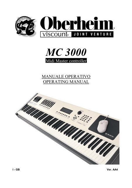
MC 3000<br />
Midi Master controller<br />
MANUALE OPERATIVO<br />
OPERATING MANUAL<br />
I - GB Ver. AA4
CAUTION<br />
RISK OF ELECTRIC SHOCK<br />
DO NOT OPEN<br />
WARNING! TO REDUCE THE DANGER OF ELECTRIC SHOCK:<br />
DO NOT REMOVE COVER (OR BACK)<br />
DO NOT EXPOSE THIS APPLIANCE TO RAIN OR MOISTURE<br />
NO USER SERVICEABLE PARTS INSIDE<br />
REFER SERVICING TO QUALIFIED SERVICE PERSONNEL<br />
This simbol is intended to<br />
alert the user to the presence<br />
of important operating and<br />
maintenance (servicing)<br />
instructions in the literature<br />
accompanying the appliance.<br />
This simbol is intended to alert<br />
the user to the presence of<br />
uninsulated “dangerous<br />
voltage“ within the product’s<br />
enclouser that may be of<br />
sufficient magnitude to<br />
constitute a risk of electronic<br />
shock to persons.<br />
“INSTRUCTIONS PERTAINING TO A RISK OF FIRE,<br />
ELECTRIC SHOCK, OR INJURY TO PERSONS“<br />
IMPORTANT SAFETY INSTRUCTIONS<br />
WARNING: When using electric products, basic precautions should always be fallowed,<br />
including the following:<br />
1) Read all instructions before using the product.<br />
2) To reduce risk of injury, close supervision is necessary when product is used near<br />
children.<br />
3) Do not use this product near water – for example, near a batnub, washbowl, kitchen<br />
sink, in a wet basement, or near a swimming pool, or the like.<br />
4) This product, either alone or in combination with an amplifier and headphones or<br />
speakers, may be capable of producing sound levels that could cause permanent<br />
hearing loss. Do not operate for a long period of time in high volume level or at a level<br />
that is unconfortable. If you experience any hearing loss or ringing in the ears, you<br />
should consult an audiologist.<br />
5) This products should be located away from heat sources such as radiators, heat<br />
register, or other products that produce heat.<br />
6) The power supply cord of the instrument should be unplugged from the outlet when left<br />
unused for a long period of time.<br />
7) Care should be taken so that objects do not fall and liquids are not spilled into the<br />
enclosure of the instrument.<br />
8) The products should be serviced by qualified personnel when:<br />
a. The power supply cord or the plug has been demaged; or<br />
b. Objects have fallen, or liquid has been spilled into the product; or<br />
c. The products has been exposed to rain; or<br />
d. The products does not appear to operate normally or exibist a marked<br />
change in performance; or<br />
e. The products has been dropped, or the enclosure demaged.<br />
9) Do not attemp to service the product beyond that described in the user-maintenance<br />
instructions. All other servicing should be referred to qualified personnel.
MC 3000<br />
Operating Manual<br />
INDEX<br />
1. General presentation<br />
1.1 The Keyboard<br />
1.2 The patch concept<br />
1.3 Let's take a look at the instrument and discover some if its features<br />
1.3.1. Wheels and sliders<br />
1.3.2. The zone keys and the zone concept.<br />
1.3.3. The display, the write key and the function keys<br />
1.3.4. The dynamic encoder, the INC and DEC keys and the cursor keys<br />
1.3.5. The Numeric pad and the mode keys<br />
1.3.6. Using the mouse and its characteristics<br />
1.3.7. The <strong>MC3000</strong> MIDI ports and MIDI potential<br />
1.3.8. The other items on the rear panel<br />
2. Let's switch on the MC 3000<br />
2.1. What the instrument does at switch-on<br />
2.2. Setting the switch-on mode<br />
2.3. Selecting the patch which will automatically appear at switch-on.<br />
3. The PROGRAM operating mode<br />
3.1. Introduction<br />
3.2. TOP page<br />
3.3. LIST<br />
3.4. VIEW<br />
3.5. INFO<br />
3.5.1 Introduction<br />
3.5.2 INFO 1<br />
3.5.3 INFO 2<br />
3.5.4 INFO 3<br />
3.5.5 INFO 4<br />
3.5.6 INFO 5<br />
3.6. PRG (send program change) function<br />
3.7. SOLO function<br />
3.8. The WRITE procedure in the PROGRAM mode.<br />
73
MC 3000<br />
Operating Manual<br />
4. The EDIT operating mode<br />
4.1. Introduction<br />
4.2. Out channels (CFG)<br />
4.3. <strong>Zone</strong> Definition (DEF)<br />
4.4. Out Messages (MSG)<br />
4.4.1. Introduction<br />
4.4.2. Messages 1<br />
4.4.3. Messages 2<br />
4.5. Curves (CRV)<br />
4.5.1. Introduction<br />
4.5.2. Curves 1<br />
4.5.3. Curves 2<br />
4.6. Controllers (CTL)<br />
4.6.1. Introduction<br />
4.6.2. Sliders<br />
4.6.3. Pedals<br />
4.7. PATCH BAY<br />
5 The CHAIN operating mode<br />
5.1. Introduction<br />
5.2. Play Chain<br />
5.3. Edit Chain<br />
6. The UTILITY operating mode.<br />
6.1. Introduction<br />
6.2. MIDI common<br />
6.2.1. Introduction<br />
6.2.2. Control Channel (CCH)<br />
6.2.3. MIDI Filter (FLT)<br />
6.2.4. MIDI Program map (MAP)<br />
6.2.5. MIDI Bulk Dump (BLK)<br />
6.3. MIDI monitor<br />
6.4. System Controls<br />
6.4.1. Introduction<br />
6.4.2. Wheels SET-UP (WHL)<br />
6.4.3. System Pedals (SPD)<br />
6.4.4. Range (RNG)<br />
74
MC 3000<br />
Operating Manual<br />
6.5. Edit Tables<br />
6.5.1. Introduction<br />
6.5.2. Port Names Table.<br />
6.5.3. Program change Tables.<br />
6.5.4. Sys-ex Tables<br />
6.6. Edit curves.<br />
6.6.1. Introduction<br />
6.6.2. Dynamic curves<br />
6.6.3. Aftertouch Curves<br />
6.7. Tools<br />
6.7.1. Introduction<br />
6.7.2. Mouse Set up<br />
6.7.3. Battery Status.<br />
6.7.4. Memory Status.<br />
6.7.5. Power on procedures.<br />
7 Additional Messages<br />
7.1 Malfunction messages<br />
7.2 Error messages<br />
7.3 Status messages<br />
8 Annex<br />
8.1 Reset Procedures (Factory settings)<br />
8.2 Panic Function<br />
75
MC 3000<br />
Operating Manual<br />
1 GENERAL PRESENTATION<br />
1.1 THE KEYBOARD<br />
The instrument is equipped with 88 weighted keys with after-touch sensitivity.<br />
The keyboard's sensitivity to key velocity and after-touch varies depending on the<br />
response curve set in the patch.<br />
Up to 48 key velocity and after-touch response curves can be set with point to point<br />
resolution by means of edit procedures we will be describing later.<br />
1.2 THE PATCH CONCEPT<br />
A patch can be defined as a program containing all the information which presets the<br />
instrument to provide a given type of performance. For example, as well as the key<br />
velocity response curves, a patch may contain the program changes assigned to the<br />
various MIDI channels and lots of other parameters to be described in greater detail later.<br />
The MC 3000 is able to store no less than 1024 patches. They can all be programmed<br />
throughout by the user and recalled in real time, allowing the user to draw on a large<br />
quantity of data without having to wait for them to be loaded from a sequencer or a<br />
computer.<br />
1.3 LET'S TAKE A LOOK AT THE INSTRUMENT and discover some if its features<br />
1.3.1 Wheels and sliders<br />
8 Sliders<br />
3 Wheels<br />
If we look at the front panel, we will find that from left to right it contains 3 wheels and 8<br />
sliders; any type of MIDI control of our choice can be assigned to each of these objects.<br />
1.3.2 The zone keys and the zone concept.<br />
8 <strong>Zone</strong> Keys<br />
In front of the sliders there are 8 zone keys. The zone is a specific region of the keyboard,<br />
which can be set as we choose to include the entire range of 88 keys or just one key, in<br />
which given parameters have been set. If a different program change assigned to a<br />
specific MIDI channel, sent to one of the MIDI OUT ports available in the instrument,<br />
corresponds to each zone, the zone is identified with a specific sound. In this case, if 8<br />
zones are activated in our patch, we have 8 different sounds distributed within the range<br />
of our keyboard. Therefore the zone is a real program assigned to a portion of the<br />
keyboard or to the whole keyboard<br />
76
MC 3000<br />
Operating Manual<br />
Each zone key has a LED indicating its activation status; when it is off, the zone is not<br />
active, while when it is on the zone is active. When the LED flashes, the relative zone<br />
is in standby condition, meaning that the zone is not yet active, but is ready to be<br />
activated next time the key is pressed.<br />
A standby status is useful if the parameters assigned to a given zone are to come into use<br />
at a certain point in the player's performance, while the overall parameters of the patch<br />
remain unchanged.<br />
1.3.3 The display, the write key and the function keys<br />
WRITE Key<br />
ESC Key<br />
The centre of the front panel contains a high contrast graphic LCD of 240x60 pixels, with<br />
neon back-lighting. Thanks to this large display and widespread use of the explanatory<br />
graphics adopted by the instrument, programming of the <strong>MC3000</strong> is simple and intuitive.<br />
In front of the display there are 8 keys; the first is the write key (WRITE) , used to save the<br />
settings which have been modified. This key is followed by 6 function keys (from F1 to F6)<br />
used to select the function which appears on the display close to the key, and then the exit<br />
key (ESC) pressed to return to the previous video page or the instrument's main menu<br />
page.<br />
1.3.4 The dynamic encoder, the INC and DEC keys and the cursor keys.<br />
Further to the right on the front panel, we find a wheel called the<br />
DYNAMIC ENCODER, used to vary parameters of any kind such as the<br />
values of a specific control selected, or the number of the patch to be<br />
selected, etc. The ENCODER can be turned in both directions to<br />
change the selected value on a continuous scale, and can also be used<br />
(in some enviroments) to move from one part of the display to another<br />
to select different options or data.<br />
Below this wheel there are 2 keys which provide the same function: the<br />
left-hand key, marked DEC, decreases a value, while the right-hand<br />
one, marked INC, increases a value. When the variation to be made is<br />
of the order of magnitude of many values, it is more convenient to use<br />
the encoder, which can provide very large variations in a short time. In<br />
the opposite conditions, the INC and DEC keys should be used, since<br />
they increase or decrease a value in steps of one unit.<br />
In front of the INC and DEC keys are the cursor keys which allow the user to move around<br />
the parameter setting fields in the display, in the direction in which the keys are located in<br />
relation to a central square bounded by 4 arrows.<br />
77<br />
6 function keys
MC 3000<br />
Operating Manual<br />
1.3.5 The Numeric pad and the mode keys.<br />
Moving to the right, we now come to the NUMERIC PAD, a<br />
combination of keys for selecting the patch number, also used to<br />
set a parameter at a given value directly, without using the<br />
encoder or the INC and DEC keys.<br />
When the value set is too high, the instrument will automatically<br />
set the maximum permitted value for the parameter.<br />
For example, when selecting a program change, for which the<br />
range is 0 to 127, if the user types the number 150 the machine<br />
will automatically set 127. Similarly, when the number typed is too<br />
low, the instrument will automatically set the minimum value<br />
permitted for that parameter. The Numeric pad is a real<br />
alphanumeric keyboard, and is thus also used for writing.<br />
The Numeric pad contains the BANK key for selecting the bank in<br />
which the patch to be recalled is located. This selection does not always start from bank<br />
A, but starts from the bank current when the operation is carried out.<br />
Finally we come to the ENTER key used to confirm the selection or confirm the name<br />
typed; each patch typed in the Numeric pad, each value set in the Numeric pad must<br />
always be confirmed with the ENTER key.<br />
BANK Key<br />
ENTER Key<br />
The last set of buttons on the right is the Mode set, consisting of 4 LED buttons allowing<br />
the user to select one of the instrument's 4 operating modes, which are:<br />
• PROGRAM MODE: Main operating mode; in this mode, the user can select the<br />
programs (patches) and use all the instrument's real-time functions.<br />
• EDIT MODE: Programming mode; this model allows the user to create and modify all<br />
the parameters in a program (patch).<br />
• CHAIN MODE: Concatenation; mode allowing the user to create and perform 128<br />
different chains of several patches.<br />
• UTILITY: This mode allows the user access to all the instrument's auxiliary functions<br />
and the creation of user tables.<br />
78
MC 3000<br />
Operating Manual<br />
Program Mode<br />
Edit Mode<br />
Chain Mode<br />
Utility Mode<br />
1.3.6 Using the mouse and its characteristics<br />
.<br />
Mouse mat<br />
The mouse mat supplied with the instrument is housed inside the far right of the front<br />
panel.<br />
The MC-3000 requires a serial Mouse having the following characteristics:<br />
• 9 pin RS-232 connector<br />
• 3 buttons<br />
• presence of PC/MS switch on the mouse. During use with the MC-3000, this switch<br />
must be set on PC.<br />
For correct operation of this peripheral, only MICE which comply perfectly with the<br />
specifications given above may be connected.<br />
As soon as the mouse is connected to the port provided in the rear panel, the mobile<br />
pointer used to select the various fields or icons on the screen appears on the display.<br />
When using the mouse, bear in mind that the left-hand key selects, the central key<br />
decreases and the right-hand one increases.<br />
In addition:<br />
• Clicking the left-hand button on a function key icon enables the relative page.<br />
• A double click of the left-hand button on the section in the top left-hand corner of the<br />
display enables the ESC function (return to the main page of the section, aborting the<br />
modifications made).<br />
To increase the legibility of the display, the Mouse pointer disappears if it is unused for<br />
about 6 seconds, and reappears next time the Mouse is moved.<br />
79
MC 3000<br />
Operating Manual<br />
1.3.7 The <strong>MC3000</strong> MIDI ports and MIDI potential.<br />
Viewed frontally, the rear panel is structured as follows.<br />
Moving from right to left, we find 2 MIDI In ports, 2 THRU ports and 8 OUT ports, all<br />
consecutively numbered.<br />
The presence of 8 separate MIDI outputs means that data can be transmitted on 128<br />
independent MIDI channels, 16 for each port.<br />
The <strong>MC3000</strong> offers much more than a large number of outputs; the instrument is able to<br />
act as a MIDI patch-bay, meaning that it is capable of providing a large number of IN-<br />
OUT setups which can be programmed for every single patch.<br />
A powerful MIDI MONITOR in the display allows the user to monitor the entire flow of data,<br />
in both DEC and HEX formats, on the various ports. The instrument offers the user 48<br />
SYS-EX tables with auto-acquisition function; it will therefore be possible to acquire the<br />
exclusive system codes from the instruments connected to the <strong>MC3000</strong>, save them inside<br />
the tables and send them as assignment of the individual zone.<br />
1.3.8 The other items on the rear panel<br />
Moving towards the left, we find the trimmer for adjusting the display contrast and 8 inputs<br />
for the pedals, the first 3 of which are defined as SYSTEM PEDALS, which act on the<br />
entire patch zone simultaneously, and the others as ASSIGNABLE PEDALS, which act<br />
only on the zones assigned to them.<br />
Finally, we come to the RS2332 serial port for connection of the mouse, the on-off switch<br />
and the network connection.<br />
LCD contrast<br />
Mouse Port 5 <strong>Zone</strong> Pedals 3 System Pedals<br />
80
MC 3000<br />
Operating Manual<br />
2. LET'S SWITCH ON THE MC 3000<br />
2.1 WHAT THE INSTRUMENT DOES AT SWITCH-ON<br />
What the MC 3000 does at switch-on depends on the settings the user has made. The<br />
user can choose between two types of switch-on: NORMAL switch-on and FAST switchon.<br />
In NORMAL mode, as soon as we switch on the instrument the display shows a<br />
message informing us about the status of the 3 lithium batteries inside the <strong>MC3000</strong>.<br />
There may be 3 types of message: the batteries are charged,<br />
they are almost flat (so the data stored inside the instrument should be saved),<br />
the batteries are flat (all user data can be lost !)<br />
Immediately afterwards, the display switches to the Program mode, showing the TOP<br />
PAGE, or the main page of this operating environment, containing the name and number<br />
of the patch selected<br />
In the other mode, as soon as the instrument is switched on the patch is selected<br />
immediately and the display does not show the name of the instrument or the message<br />
indicating the status of the batteries, unless the batteries are flat, in which case the<br />
81
MC 3000<br />
Operating Manual<br />
message becomes especially urgent, because the user may have lost all the data the<br />
instrument contained.<br />
N.B.: The estimated lifetime of the lithium batteries installed in the MC-3000 is about 4<br />
years. However, specific conditions of use (such as high operating temperatures) may<br />
significantly shorten the battery lifetime. Users are urged to save the memory by MIDI<br />
Bulk Dump as soon as the instrument gives the battery low warning.<br />
2.2. SETTING THE SWITCH-ON MODE.<br />
• Press the UTILITY key on the right of the front panel (MODE section).<br />
At this point the display will show the 6 sections of the UTILITY operating mode.<br />
• Select the number 6 (TOOLS) in the bottom right-hand corner of your display using the<br />
function key provided (or by turning the encoder until the word TOOLS on the display is<br />
highlighted and confirming with ENTER). The display will show the following:<br />
POWER ON<br />
PROCEDURES page<br />
This is the first page of the TOOLS section, relating to the mouse parameters. The 4<br />
pages of the section are shown in the bottom of your display, with the page currently<br />
displayed with reverse illumination.<br />
• Now press F4 (PWR icon) to select the fourth page, entitled POWER ON<br />
PROCEDURES. The video page which appears is as follows:<br />
82
MC 3000<br />
Operating Manual<br />
Switch-on<br />
mode selection<br />
function<br />
• Use the cursor keys to move to the line where the words POWER ON TYPE appear: at<br />
this point the current function (NORMAL mode in the illustration) is selected, and the<br />
word NORMAL will be highlighted.<br />
• The INC and DEC keys or the encoder can now be used to vary the setting of the<br />
switch-on mode from NORMAL to FAST and vice-versa.<br />
• Press ESC to exit (Utility Menu page). All modifications will be saved automatically.<br />
2.3 SELECTING THE PATCH which will automatically appear at switch-on.<br />
You can choose the patch which will automatically appear when the instrument is switched<br />
on. To do this, access the POWER ON PROCEDURES page (just described) in the<br />
TOOLS section 6 of the UTILITY operating mode<br />
• Now select the third line where the words PATCH POWER ON appear, using the cursor<br />
keys to move around the display.<br />
Automatic switchon<br />
patch selection<br />
function<br />
• Set the number of the patch you wish to appear automatically when the instrument is<br />
switched on using the encoder or the alphanumeric keypad. The rectangle in the<br />
bottom right-hand corner where the word LAST appears refers not to a page but to a<br />
special function. When this function is selected using the corresponding function key<br />
(F6), the last patch selected before switch-on will automatically appear.<br />
• Press ESC to exit (Utility menu)<br />
Function Key<br />
LAST<br />
N.B. Function Key F6 (LAST) works only when the field PATCH POWER ON is selected.<br />
83
3.1 INTRODUCTION<br />
MC 3000<br />
Operating Manual<br />
3. THE PROGRAM OPERATING MODE<br />
As already mentioned, this operating mode is automatically selected in switch-on. On<br />
many other keyboards, its equivalent is known as the Play mode, meaning that the<br />
keyboard is ready to be played. The keyboard also plays in the other modes, but the<br />
program and chain modes are the typically "live" modes, because they allow the<br />
immediate change of the patches prepared for the various musical and instrumental<br />
contexts.<br />
3.2 TOP PAGE<br />
The first page which appears when the PLAY mode is accessed, and therefore also at<br />
switch-on, is the TOP PAGE<br />
.<br />
Current Page Operating Mode <strong>Zone</strong> icons<br />
Bank and<br />
Number<br />
Patch Name<br />
Comment Field<br />
Selected<br />
Function<br />
Available Functions<br />
This page contains all the information necessary during performance of a song. The<br />
centre of the display shows the name of the bank and the number and name of the patch<br />
being played, with a comments field of 24 letters.<br />
In the top of the screen, we find the name of the page and the current operating mode,<br />
while the box in the top right-hand corner indicates the activation status of the 8 zones in<br />
that patch; the solid circles indicate the active zones which are being played, while the<br />
empty ones show the active zones not being played, and the zones surrounded by<br />
dotted lines are in standby mode. No icons appear for the zones not active in that<br />
patch; if only 4 zones are active in that patch, only 4 circles will appear, solid, empty or<br />
with dotted lines depending on the conditions described above. At the bottom of the<br />
screen there are rectangles indicating the pages of the Program mode. Here again, the<br />
page selected, and thus the rectangle selected, is indicated by reverse lighting.<br />
All the data input devices, such as the encoder, the INC and DEC keys and the numerical<br />
keypad are enabled for patch selection; if the keypad is used a message on the display<br />
will show the sequence of data entered with regard to the patch number and bank.<br />
Remember that selections made from the numerical keypad must be confirmed by<br />
pressing ENTER.<br />
84
MC 3000<br />
Operating Manual<br />
3.3 LIST<br />
If LIST is selected using the corresponding function key F2 from the TOP PAGE or from<br />
any other successive page in the program mode, the second page of the program mode,<br />
called the LIST PAGE, appears. The top of the page shows the name of the page, the<br />
current operating mode and the number of the selected patch.<br />
Current Patch<br />
selected<br />
Tens<br />
selection<br />
This page contains the list of the patches present in the current bank, displayed in groups<br />
of 10 patches at a time (except for the last group, from 120 to 128). The group shown as<br />
soon as this page is accessed is the one to which the current patch belongs. For<br />
example, if we are in patch n. 02 of bank A when we access the LIST PAGE, this page will<br />
show the group which goes from patch n. 00 to n. 09 of the respective bank A. At this<br />
point, if we wish to display the groups which follow we simply press F6 located in line with<br />
the rectangle marked +10, in the bottom right-hand corner of the display, and whenever<br />
the key is pressed the groups belonging to gradually rising tens, 30-39, 40-49, 50-59, etc.,<br />
will appear. Similarly, to display the previous groups press F5 close to the rectangle<br />
marked -10, and whenever the key is pressed the groups of lower tens, 90-99, 80-89, 70-<br />
79, etc., will appear.<br />
When the lowest group, 00-09, is displayed, only +10 appears in the bottom right-hand<br />
corner, meaning that only F6 is enabled, while F5 will be disabled because it is not<br />
possible to select a group lower than the group displayed.<br />
When the group displayed is the highest, the display will only show the rectangle marked -<br />
10, meaning that only function key F5 is enabled.<br />
85
MC 3000<br />
Operating Manual<br />
Once the group required is displayed, the chosen patch can be selected using the cursor<br />
keys or the encoder, and as soon as the choice is confirmed with ENTER the instrument<br />
switches to the desired patch, which will appear with its TOP PAGE<br />
The usefulness of the LIST page lies in the rapid consultation it allows. For example, if we<br />
do not remember the number to which we have associated the patch required, instead of<br />
scrolling through them one by one in the TOP PAGE, the patches can be displayed in<br />
groups of ten at a time. Note that the patch being played remains active even during the<br />
location process, until ENTER is pressed.<br />
3.4 VIEW<br />
F3, below the rectangle marked VIEW on the display, can be pressed from the previous<br />
page or any other page in the program mode to select the VIEW PAGE. In this page, the<br />
name of the page, the current operating mode and the number of the selected patch<br />
appear in the top of the display.<br />
This page shows the setup of the splits and layers relating to the current patch.<br />
Each letter which appears on the right and left of the display under the image of the<br />
keyboard represents a zone, and each of these is associated to a line which informs us of<br />
the key range of that specific zone, or in other words the region of notes which the zone<br />
covers. Any zone overlaps or layers are immediately visible in this window.<br />
Let us suppose we have a patch with 4 zones active, each of which associated to a<br />
different MIDI channel and Program Change, so basically we have 4 different instruments<br />
available on the keyboard. When the VIEW PAGE is accessed, we can immediately see<br />
where these instruments are positioned, and the placing of any layers. One possible<br />
video page is shown below:<br />
By scrolling over the letters representing the zones using the cursor keys or the encoder,<br />
the user can display the key range of the selected zone in detail on the rectangle marked<br />
"current range" in the centre of the lower part of the display.<br />
Selection of zone A and detailed information about its key range.<br />
86
MC 3000<br />
Operating Manual<br />
Selection of zone B and detailed information about its key range.<br />
Selection of zone C and detailed information about its key range.<br />
Selection of zone D and detailed information about its key range.<br />
Press F1 or ESC to leave this function and go to the TOP PAGE.<br />
The function key F6 switches directly to the EDIT environment of the ZONE DEFINITION<br />
page, which allows the user to modify the key ranges<br />
So if F6 is pressed the following page will appear :<br />
Key for direct<br />
access to the<br />
EDIT mode<br />
87
MC 3000<br />
Operating Manual<br />
For the procedure for making the modifications in this page, refer to the EDIT section of<br />
this manual, point 4.3<br />
Press ESC twice to go back to the TOP PAGE<br />
3.5 INFO<br />
3.5.1 Introduction<br />
F4, below the rectangle marked INFO, can be pressed on any program mode page to<br />
select the last page of the mode, the INFO page. In actual fact this is a multiple page,<br />
consisting of 5 subpages. Naturally, the first subpage which appears as soon as the INFO<br />
page is selected is Info1. F5, under the word PAGE, can be pressed to scroll through the<br />
successive subpages in increasing order up to 5, after which when F5 is pressed again<br />
the system returns to INFO 1.<br />
The name of the page (INFO) and the current mode appear at the top of all 5 subpages,<br />
alongside the circles indicating the activation status of the current patch zones.<br />
3.5.2 INFO 1<br />
<strong>Zone</strong> status<br />
Assigned Port<br />
Assigned<br />
Channel<br />
<strong>Zone</strong> columns<br />
PAGE (F5)<br />
In this first subpage of the Info page, is reported a prospect where are shown the 8 zones<br />
(colums from A to H) and, for each of them, is reported :<br />
• The activation status (ON =Active, OFF = Not active, SB = Standby)<br />
• The MIDI OUT port assigned to each zone<br />
• The MIDI channel assigned to each zone<br />
88
3.5.3 INFO 2<br />
MC 3000<br />
Operating Manual<br />
<strong>Zone</strong> PG<br />
Auxiliary<br />
messages Y/N<br />
<strong>Zone</strong> columns<br />
This subpage displays the program changes, whether or not auxiliary messages are<br />
present and the base volumes for each zone. The base volume is the volume of each<br />
zone when the patch is selected, which must be set and then saved with the edit<br />
procedures. The volumes of the individual zones can be varied temporarily while playing<br />
using the sliders, the volume pedal or any other controller, but are not saved, and are lost<br />
whenever the user exits from the patch concerned and then re-selects it, or whenever the<br />
MC 3000 is switched off. On the other hand, the volumes you assign to the zones in the<br />
EDIT environment can be saved and recognized as base volumes, so whenever you<br />
switch on the instrument and select that specific patch, the zones will retain the variations<br />
in volume you have made.<br />
Therefore, temporary variations in volume made in the program mode will never appear in<br />
this subpage.<br />
3.5.4 INFO 3<br />
CC assigned to<br />
slider 1<br />
CC assigned to<br />
slider 2<br />
Colonne delle<br />
<strong>Zone</strong><br />
CC assigned to<br />
slider 3<br />
This subpage displays the type of control on which each of the first 3 sliders act for each<br />
zone.<br />
3.5.5. INFO 4.<br />
This subpage displays the type of control on which sliders 4, 5 and 6 act for each zone.<br />
89
MC 3000<br />
Operating Manual<br />
3.5.6. INFO 5.<br />
Jump to related<br />
EDIT procedures<br />
This subpage displays the type of control on which sliders 7, 8 and 9 act for each zone.<br />
In all the INFO subpages the user can press function key F6 (next to the EDIT icon) to<br />
move straight to the relative EDIT page corrisponding to the section present on the<br />
display.<br />
If ESC is pressed during display of the INFO video page, the MC 3000 returns to the TOP<br />
PAGE; use the dedicated function keys to move directly to the Program Mode functions<br />
analyzed previously.<br />
3.6 PRG (send program change) FUNCTION<br />
The PRG (send Program Change) function which is the exclusive property of the TOP<br />
PAGE allows the user to send a Program Change message which does not belong to the<br />
patch programming data. This function is particularly useful, for example to recall a given<br />
sound on a connected expander for testing purposes, without having to save it.<br />
Send program<br />
change (PRG)<br />
function<br />
From the TOP PAGE, press key F5, corresponding to the PRG icon. The following video<br />
page will appear:<br />
The user is able to use the following fields:<br />
90
MC 3000<br />
Operating Manual<br />
• OUTPUT PORT: Selects the MIDI OUT port on which the Program Change is to be<br />
sent (from 01 to 08). The name attributed to selected port, which can be defined by the<br />
user, also appears beside the number (see UTILITY - Tables section of this manual).<br />
• CHANNEL NUMBER: Selects the MIDI channel on which the Program Change is to be<br />
sent (from 01 to 16).<br />
• BANK NUMBER: This field can be used to send a Bank Changee (Bank select LSB)<br />
message together with the program change. Enter the appropriate value, bearing in<br />
mind that if this field is OFF, the Bank Select message will NOT be sent.<br />
• PROGRAM CHANGE: Number of the program change to be sent (0-127).<br />
Use the CURSOR keys to select the field to be modified and enter the appropriate value<br />
for it using the encoder, the INC and DEC keys or the numerical keypad.<br />
Once the settings have been made, press ENTER to send the message without leaving<br />
the current page, or F6 (OK icon) to send the message and return to the TOP PAGE.<br />
Press ESC to leave the current page without sending a message.<br />
3.7 SOLO function<br />
Another exclusive function of the TOP PAGE is the SOLO function, accessed by pressing<br />
function key F6 (SOLO icon).<br />
This function keeps only the zone selected by the user active, switching all the other<br />
zones currently active to Stand-by status. When the function key is pressed, the following<br />
video page appears on the display:<br />
All the LEDs relating to the active zones will start to flash awaiting the selection. Press the<br />
key for the zone to be left active and the MC-3000 will return to the Top Page, switching all<br />
the other zones to Stand-by mode; when function key F6 (SOLO) is pressed again, the<br />
patch will be restored to the basic conditions.<br />
3.8 THE WRITE PROCEDURE IN THE PROGRAM MODE.<br />
This WRITE is used to save all the settings made by the user inside the patch. Since<br />
these settings are made in the EDIT environment, the WRITE key is of fundamental<br />
importance in the EDIT mode but might seem useless in the PROGRAM mode. In fact,<br />
the WRITE key is also useful in the PROGRAM mode because it activates a special video<br />
page from which the location of the selected patch can be changed, and it can be<br />
assigned a name and a specific comment.<br />
The comment field is only enabled in the WRITE video page of the PROGRAM and EDIT<br />
modes, since in the other modes the saving procedure does not refer to the patch, but to<br />
other parameters or entities such as the key velocity curves, tables, chains, etc., which do<br />
not have a comment field.<br />
91
MC 3000<br />
Operating Manual<br />
When the WRITE key on the front panel of the instrument is pressed, the display will show<br />
the following video page:<br />
Modifies the<br />
patch comment<br />
field<br />
Modifies the<br />
patch name<br />
• The CURRENT LOCATION field indicates the current Memory location (bank and<br />
number) and the name of the patch it contains.<br />
• The DESTINATION field, which can be modified by the user, indicates the memory<br />
location (bank, number and name of the patch contained there) on which the current<br />
patch will be memorized. Use the data input devices (encoder, numerical keypad,<br />
INC/DEC keys) to select the desired location.<br />
Press the WRITE key again to confirm the operation or ESC to abort it.<br />
The function keys F5 (TEXT icon) and F6 (NAME) icon allow the user to modify the<br />
comments field and the patch name respectively. When one of the two choices is made,<br />
the display will switch to the respective video pages, structured as shown below:<br />
A dash blinking under the first character of the name indicates that this character is<br />
selected and can be modified using the data input devices (including the number keypad).<br />
The cursor keys can be used to locate on other characters and modify them with the same<br />
procedure, thus making up the new patch name. The function keys enable the following<br />
functions:<br />
• F1 (INS) selects the INSERT writing mode (the blinking cursor doubles in thickness),<br />
where each character selected using the number pad is inserted, moving all the other<br />
characters forward one place. When this mode is not selected, the characters entered<br />
overwrite the existing ones.<br />
• F2 (BKS) provides the BACKSPACE function, used to delete the character before the<br />
one selected.<br />
• F3 (DEL) enables the DELETE function which deletes the selected character.<br />
• F4 (SPC) inserts a SPACE carachter<br />
92
MC 3000<br />
Operating Manual<br />
• F5 (CAPS) enables/disables the CAPITAL LOCK condition (shown in the top right-hand<br />
corner of the display). With this function enabled, the letters selected using the numeric<br />
pad will be capitals; in OFF they will be lower case letters.<br />
F6 (DONE) terminates the patch renaming operations, returning the instrument to the<br />
previous video page, where the user can decide whether to save all the modifications by<br />
pressing WRITE or abort them by pressing ESC.<br />
4.1 INTRODUCTION.<br />
4. THE EDIT OPERATING MODE<br />
This is the operating mode which allows the user to set all the parameters of the patch<br />
selected and to create all the personalized patches needed. To make these settings, the<br />
user first selects a patch from PROGRAM mode and then accesses the EDIT environment<br />
by pressing the relative key on the right of the instrument front panel. As soon as this key<br />
is pressed, the display shows the menu video page indicating the 6 sections of the EDIT<br />
mode, each of which can be accessed using the relative function keys or by moving onto<br />
the section to be selected with the encoder or the cursor keys and confirming using<br />
ENTER.<br />
Each section may consist of one or two pages. To facilitate the edit procedures, the MC<br />
3000 allows the user to move around the 5 seconds without leaving the current page and<br />
accessing the menu. To allow this, all the video pages contain rectangular icons which<br />
give access to the video pages of the other sections by means of the corresponding<br />
function keys, except for the patch bay section which is treated separately:<br />
• OUT CHANNELS: This section allows the user to define the activation status, MIDI<br />
channels and output ports of each of the 8 zones in the patch<br />
• ZONE DEFINITIONS: Define the Key-range, transposition and mode of the zone<br />
• OUT MESSAGES: Here the user can assign all control messages to zones like<br />
Program Change, Bank Select, Volume, Panpot, Reverb, Chorus, including System<br />
exclusive and auxiliary messages<br />
• CURVES: This section allows the user to assign the Dynamic and Aftertouch curve to<br />
each zone.<br />
• CONTROLLERS: Definition of the Sliders and Pedals assigned to each zone<br />
• PATCH BAY: Configuration of the MIDI PATCH BAY. For each patch it is possible to<br />
create situations of MIDI OUTs union and situations containning the redirection of one<br />
ore more MIDI INs on one or more MIDI OUTs<br />
93
MC 3000<br />
Operating Manual<br />
4.2. OUT CHANNELS (CFG)<br />
This section, also known as the setup section, allows the user to define the activation<br />
status, MIDI channel and OUTPUT PORT of each zone<br />
<strong>Zone</strong> selection<br />
MIDI OUT Port<br />
<strong>Zone</strong> status<br />
TX Channel<br />
The name CONFIGURE, representing the second section name, the name of the current<br />
patch and the lights indicating the activation status of its zones all appear at the top of the<br />
display. Immediately below is a field where the user can select the individual zone of the<br />
patch to be set up. To do this, the user uses the cursor keys to locate on the ZONE= field<br />
and then selects the zone desired using the INC and DEC keys or the encoder.<br />
The activation status of the selected zone appears in the central window of the display<br />
and can be modified using the encoder or INC and DEC once the user has located on the<br />
STATUS option using the cursor keys. The same window also shows the MIDI port<br />
assigned to the same zone (PORT field), which can be modified by using the cursor keys<br />
to locate next to PORT and turning the encoder or pressing INC and DEC using the<br />
procedure already described above. The name assigned to the MIDI port to be selected<br />
in the TABLE section of the UTILITY operating mode also appears alongside PORT.<br />
The last field in the central window (TX CHANNEL) specifies the MIDI channel on which<br />
the selected zone transmits its messages. This may be modified using the same<br />
procedure: the user locates the cursors in the TX CHANNEL field and modifies the MIDI<br />
channel using the INC and DEC keys or by turning the encoder.<br />
The bottom of the display contains the usual icon rectangles indicating the various<br />
sections, with the one indicating the current section illuminated in reverse. Pressing the<br />
function keys relating to these rectangles gives access to the corresponding sections.<br />
When programming is complete, to save these modifications press WRITE and follow the<br />
procedure described at point 3.8.<br />
4.3. ZONE DEFINITION (DEF)<br />
The ZONE DEFINITION section can be accessed from any section video page or any<br />
EDIT mode page by pressing F2, next to the DEF icon. This section can also be<br />
accessed from the EDIT MENU video page by using the cursor keys or encoder to select<br />
option 2 on the display and then confirming with ENTER.<br />
Here the user can define the range of the zone, meaning its extension over the keyboard,<br />
creating zone layers and splits. He can also establish the zone transposition for a<br />
maximum range of 2 octaves above or 2 octaves below the current range, and establish<br />
whether the selected zone will transmit note messages in polyphonic or mono mode, and<br />
whether or not the portamento messages generated by the master are to be transmitted.<br />
94
MC 3000<br />
Operating Manual<br />
<strong>Zone</strong> selection<br />
Back to the<br />
Configuration<br />
Page<br />
After using the cursor keys to locate in the ZONE field, the user can use the encoder or<br />
INC and DEC to select the zone to be edited.<br />
With the cursor in the LO-KEY or HI-KEY fields, the encoder or INC and DEC can be<br />
used to select the lowest and highest notes of the zone respectively, thus setting its range.<br />
In the display, the continuous line immediately below the image of the keyboard shows the<br />
range of the selected zone, and will alter in response to the modifications made in these<br />
two fields.<br />
Similarly, with the cursor in the TRANSPOSER field the user can set the degree of<br />
transposition of the zone using the encoder or INC and DEC.<br />
With the cursor in the MODE field, the user can set MONOphonic or POLYphonic mode<br />
for transmission of the note messages.<br />
In the PORTAMENTO field, the user can select ON or OFF status using the encoder or<br />
INC and DEC, to set whether the current zone is to transmit the portamento.<br />
Important note: The MONO mode message is a strictly MIDI datum and thus a<br />
transmission parameter, so the keyboard is always polyphonic. However, for mono<br />
transmission the receiver unit must be capable of receiving in this mode, as otherwise the<br />
desired effect is not created.<br />
When programming is complete, to save these modifications press WRITE and follow the<br />
procedure described at point 3.8.<br />
4.4 OUT MESSAGES (MSG)<br />
4.4.1 Introduction<br />
The OUT MESSAGES section can be accessed from the previous section video page or<br />
any EDIT mode section by pressing F3, next to the DEF icon. This section can also be<br />
accessed from the EDIT MENU video page by using the cursor keys or encoder to select<br />
option 3 on the display and then confirming with ENTER. Here the user can assign all<br />
control messages except notes to zones. All these messages, including any exclusive<br />
code messages assigned to the zone, are inserted when the patch is selected. In this<br />
section, the user can define the auxiliary zones, which are the zones destined to control<br />
devices which do not need note messages, such as multieffects devices<br />
4.4.2. MESSAGES 1<br />
<strong>Zone</strong><br />
CC Section<br />
PRG<br />
Definition<br />
Section<br />
95
MC 3000<br />
Operating Manual<br />
The first page to appear when the section is selected is the MESSAGES 1 page. From left<br />
to right, the top of the display shows the name of the page, the name of the current patch<br />
and the lights which indicate the zones' activation status.<br />
Immediately below is the zone selection field, where the cursor can be located using the<br />
cursor keys to select the zone to be edited with the INC and DEC keys or the encoder.<br />
Alongside the central window of the display there is a vertical icon marked PRG, indicating<br />
that this window is dedicated to setting of the program, or in other words of the sound or<br />
patch, of the expander assigned to that zone.<br />
The first field, TABLE, selects one of the 64 tables (the contents of which can be set in the<br />
UTILITY/TABLES section) where the names of the sounds contained in the connected<br />
expander associated to the relative program change messages reside. The user can<br />
locate in this field using the cursor keys and then select various lists of sounds relating to<br />
different expanders, 16 of them already preset in the instrument memory (P1 - P16,) and<br />
48 of them, (U17 - U64), programmable by the user. When this field is set in OFF status,<br />
no table is associated to the current zone.<br />
Alongside the TABLE field, the TABLE NAME field displays the name of the selected<br />
table. This field is for display only, meaning that no modifications are possible since the<br />
name has been assigned to the respective table when it was constructed.<br />
Underneath the TABLE field is the PRG field, with the PRG NAME field beside it.<br />
PRG stands for program change, and here the user can set the number of the program<br />
change assigned to the selected zone, which will send it on the MIDI channel and port<br />
specified in the CONFIGURE section.<br />
If the PROGRAM field is set in OFF status, no program change will be sent to the zone<br />
concerned.<br />
The name of the sound corresponding to the program change number selected, in<br />
accordance with the contents of the TABLE set, appears alongside this field as a message<br />
for display only.<br />
The BANK fields (MSB and LSB) define the value to be attributed to the BANK SELECT<br />
messages. These messages can be used to change the bank of sounds selected on the<br />
connected expander (refer to the service manual for information about the type and value<br />
of the Bank select message recognized by your expander).<br />
After locating on this field with the cursor keys, select the value to be attributed to the<br />
BANK SELECT messages, BANK SELECT MSB (Control Change 0 value) and BANK<br />
SELECT LSB (Control Change 32 value).<br />
Important note: in view of the characteristics of the Bank Select MSB and LSB<br />
messages, to ensure that the message concerned is recognized, it must be followed<br />
by a Program Change message. Bear in mind that while when the patch is recalled, the<br />
MC-3000 performs this sequence automatically, during editing the Program Change must<br />
be updated in manual mode immediately after one of the Bank select values has been<br />
modified.<br />
Although the OFF condition (message not transmitted) is available, it is important always<br />
to set the appropriate Bank Select value.<br />
96
MC 3000<br />
Operating Manual<br />
The last line of this video page (identified as CC) contains the main zone control<br />
parameters, which will be sent when the patch is recalled. The parameters concerned<br />
relate to the VOLUME level (corresponding to the value of Control Change 7), the<br />
positioning within the stereo panorama PAN-POT (control change 10), and the level of the<br />
Reverb effect (REV, control change 91) and the Chorus effect (CHO, control change 93).<br />
All the parameters listed above offer the OFF status (message not sent) and a range of 0-<br />
127.<br />
The MORE icon (associated with key F6) in the function key section allows access to the<br />
second EDIT page of the MESSAGES section.<br />
4.4.3 MESSAGES 2.<br />
Access to the second<br />
EDIT page of the<br />
MESSAGES section.<br />
<strong>Zone</strong><br />
Sys Ex<br />
Auxiliary<br />
messages<br />
This is the second page of the OUT MESSAGES section, which can only be accessed<br />
from the previous page, by pressing function key F6. Note that in this page the icon<br />
corresponding to F6 is marked BACK instead of MORE, indicating that the key should be<br />
pressed to return to the previous page.<br />
The word AUX in a vertical icon alongside the central window of the display indicates that<br />
the window is dedicated to setting of the auxiliary messages. These messages do not<br />
form part of the current zone but may be sent together with it in order to control devices<br />
which do not need notes (multi-effects devices, mixers, etc.) without having to sacrifice a<br />
split point. Each of the 8 auxiliary zones is simply a sort of program, which unlike the zone<br />
to which it is associated, does not have any keyboard range assigned to it. For example,<br />
if we wish the singer's reverb to be modified when a program change is sent to an<br />
expander, an auxiliary zone controlling the singer's reverb can be associated to the zone<br />
concerned.<br />
In the AUX window are reported the following fields:<br />
• PORT: MIDI OUT port selection for the auxiliary messages.<br />
• PORT NAME: This field show the name of the MIDI OUT port selected (to modify this<br />
name please see UTILITY / TABLES section).<br />
• CHANNEL: Setting of the MIDI channel for the auxiliary messages.<br />
• PG: Auxiliary program change number (sended out when patch is recalled)<br />
• CC # and CC VALUE: Set up of a Control Change and its related value that will be<br />
send out on the MIDI port and channel specified for this section<br />
97
MC 3000<br />
Operating Manual<br />
Below the central window there is a window identified by the icon S, indicating that it is<br />
dedicated to exclusive systems.<br />
After locating in the SYS N field, the user can select the desired exclusive system table by<br />
turning the encoder or pressing the INC and DEC keys.<br />
The MC 3000 offers the user 16 preset tables in the instrument memory, P1-P16, and 48,<br />
U17-U64, which can be programmed by the user himself in the UTILITY mode.<br />
Each table contains exclusive system strings. When the patch is recalled, they are taken<br />
from the table and sent to the connected expander before all the others.<br />
CAUTION: When the exclusive code selected has a RESET function, the unit connected<br />
by MIDI takes a few milliseconds to reset the data; during this time, it is probable that the<br />
other messages belonging to the zone will be ignored.<br />
The SYS NAME field which appears alongside the SYS N field is for display only and will<br />
contain the name corresponding to the Sys-ex table selected.<br />
On completion of programming, to save these modifications press the WRITE key and<br />
follow the procedure described in point 3.8.<br />
4.5 CURVES (CRV)<br />
4.5.1 Introduction<br />
The user may press F4, below the CVR icon, from the previous page or any other page or<br />
any section of the EDIT mode to access the CURVES section, where he is able to assign<br />
the dynamic or aftertouch curve to each zone. These curves are chosen from the 16<br />
preset in the instrument's ROM, or the 48 curves the user has set himself in the UTILITY /<br />
EDIT CURVES section.<br />
4.5.2 CURVES 1.<br />
Here again, the top of the display shows the name of the current page, the name of the<br />
current patch and the lights indicating the zone activation status.<br />
<strong>Zone</strong><br />
Dynamic curve<br />
number<br />
appearance<br />
of the curve<br />
Name of the selected<br />
Dynamic curve<br />
After locating the zone field with the cursor keys, the user can select the zone where the<br />
dynamic response curve will be set using the encoder or INC and DEC. After using the<br />
cursor keys to move down to the CURVE N. field, the user can select the dynamic<br />
response curve to be applied to the chosen zone.<br />
Alongside this field is a window showing the appearance of the curve to be selected. This<br />
window is for display only, and cannot be used to modify the curve. To modify the curve,<br />
98
MC 3000<br />
Operating Manual<br />
the user must access the UTILITY mode in the DYNAMIC CURVES page of the EDIT<br />
CURVES section and follow the instructions given in the part of this manual which<br />
discusses that page. The name of the selected curve also appears, for display only.<br />
The possibility of assigning different dynamic curves to several zones allows the user to<br />
create dynamic layers and splits between different zones and MIDI channels. For<br />
example, it is possible to create a patch with 2 overlapping zones where the first controls<br />
the piano sound with a curve capable of reading all Key Velocity values, and the second<br />
controls a brass sound but with a curve which only reads values above 70. This means<br />
that as when the keyboard is played with a Key Velocity of less than 70, only the piano will<br />
sound, but as soon as this value is exceeded, the brass sound will be overlapped with the<br />
piano (dynamic Layer). If the dynamic curve of the piano were programmed to respond up<br />
to a Key Velocity value of 70, above that value the piano would no longer sound and only<br />
the brass would be heard (dynamic Split). This example can be extended to a larger<br />
number of overlapping zones transmitting on different MIDI channels.<br />
The bottom of the display contains the usual icon rectangles indicating the sections of the<br />
EDIT mode, with the current section shown in reverse.<br />
The last rectangle contains the word MORE. F6 can be pressed for access to the second<br />
page of the section, dedicated to the Aftertouch curves which can be assigned to the<br />
single zones.<br />
4.5.3 CURVES 2.<br />
This page, which as just stated can only be selected from the CURVES1 page by pressing<br />
function key F6, contains a video page similar to the previous one, with the sole difference<br />
that here the Aftertouch curve is displayed. These curves are chosen from the 16 preset in<br />
the instrument's ROM, or the 48 curves the user has set himself in the UTILITY / EDIT<br />
CURVES section.<br />
Here again, the top of the display shows the name of the current page, the name of the<br />
current patch and the lights indicating the zone activation status. Below this is the ZONE<br />
field. After locating on this field with the cursor keys, the user can select the zone where<br />
the dynamic response curve will be set using the encoder or INC and DEC.<br />
After using the cursor keys to move down to the CURVE N. field, the user can turn the<br />
encoder or use the INC and DEC keys to select the Aftertouch response curve to be<br />
applied to the chosen zone. Alongside this field is a window showing the appearance of<br />
the curve to be selected. This window is for display only, and cannot be used to modify<br />
the curve. To modify the curve, the user must access the UTILITY mode in the<br />
AFTERTOUCH CURVES page of the EDIT CURVES section and follow the instructions<br />
given in the part of this manual which discusses that page.<br />
The name of the selected curve also appears, for display only.<br />
99
MC 3000<br />
Operating Manual<br />
<strong>Zone</strong><br />
Aftertouch<br />
curve number<br />
Name of the selected<br />
Aftertouch curve<br />
Appearance<br />
of the curve<br />
The last rectangle is marked MORE. The corresponding function key F6 can be pressed<br />
to return to the previous page of the CURVES section. The possibility of assigning<br />
different Aftertouch curves to several zones allows the user to create Aftertouch layers<br />
and splits between different zones and MIDI channels. When programming is complete, to<br />
save these modifications press WRITE and follow the procedure described at point 3.8.<br />
4.6. CONTROLLERS (CTL).<br />
4.6.1 Introduction<br />
The user may press F5, close to which the CTL icon appears on all video pages, from any<br />
EDIT page or section to access the CONTROLLERS section.<br />
Here the user can define for each zone one or more controllers (slider and pedals) that<br />
will move the value of a specific MIDI CONTROL CHANGE (CC).<br />
4.6.2 SLIDERS<br />
<strong>Zone</strong><br />
Dafault<br />
Value<br />
CC assigned<br />
to slider<br />
The first page of the CONTROLLERS section, which appears automatically when the<br />
section is selected, is dedicated to the sliders, and is thus called SLIDERS.<br />
Here again, the top of the display contains the name of the current page, the name of the<br />
current patch and the lights indicating the activation status of its zones. The ZONE field<br />
appears below this; after locating here with the cursor keys, the user can turn the encoder<br />
or use the INC and DEC keys to select the zone where a specific type of control is to be<br />
assigned.<br />
The 8 sliders are shown in the centre of the display. Numerical values which identify the<br />
type of control assigned to the slider corresponding, or OFF indicating that the slider in<br />
question is not active in the current zone, appear below each slider in line with CC NR.<br />
After locating on these values with the cursor keys, the user can select the type of control<br />
to be assigned to the corresponding slider. The name of the control selected will appear<br />
automatically in the top of the screen, beside CC NAME, as a display message only.<br />
100
MC 3000<br />
Operating Manual<br />
The word DEFAULT appears below CC NR. In line with this, the value of that slider for<br />
the control assigned to it when the patch is recalled (i.e. the default value) appears<br />
below each slider. After locating on these values with the cursor keys, the user can turn<br />
the encoder or use the INC and DEC keys to modify them.<br />
Important note: when setting the default value of the volume, reverb and chorus, make<br />
sure that this operation has not already been carried out in the MESSAGES 1 page; To<br />
avoid the presence of contradictory data, it is advisable to set OFF status for all data<br />
which could be set in other pages.<br />
4.6.3 PEDALS<br />
The PEDALS page can only be accessed from the SLIDERS page of the CONTROLLERS<br />
section, by pressing the F6 function key.<br />
MC 3000 is able to support on its inputs both switch (i.e. sustain) and expression pedals<br />
(i.e. volume). Evidently a switch pedal will send only two MIDI messagges (0 when pedal<br />
is released and 127 when pedal is pressed) while an expression pedal will be able to send<br />
the entire data range (from 0 to 127)<br />
Please note that the instrument supports the following types of pedals:<br />
• Switch Pedals: Pedals with a NORMALLY CLOSED contact<br />
• Expression Pedals: Pedals equipped with a stereo jack connector. The input<br />
impedence must be included from 10 to 22 Kohm.<br />
N.B The use of unsuitable padals may causes damage to the machine's electronic<br />
components.<br />
<strong>Zone</strong><br />
Default<br />
Value<br />
CC assigned<br />
to pedals<br />
Here again, the top of the display contains the name of the current page, the name of the<br />
current patch and the lights indicating the activation status of its zones.<br />
The ZONE field appears below this; after locating here with the cursor keys, the user can<br />
turn the encoder or use the INC and DEC keys to select the zone where a specific type of<br />
control is to be assigned.<br />
The 8 pedals are shown in the centre of the display.<br />
Numerical values which identify the type of control assigned to the pedal corresponding, or<br />
OFF indicating that the pedal in question is not active in the current zone, appear below<br />
each pedal in line with CC NR. After locating on these values with the cursor keys, the<br />
user can turn the encoder or use the INC and DEC keys to select the type of control to be<br />
assigned to the corresponding pedal. The name of the control selected will appear<br />
automatically in the top of the screen, beside CC NAME, as a display message only.<br />
The word DEFAULT appears below CC NR.<br />
101
MC 3000<br />
Operating Manual<br />
NOTE: the first 3 pedals are marked with the letter S since they also act as System<br />
pedals; their characteristic is that they control all the zones simultaneously.<br />
As the above indicates, these three pedals are able to control one or more zones of the<br />
user's choice simultaneously with the system, thus allowing complete freedom when<br />
selecting the configuration.<br />
Refer to the UTILITY/SYSTEM CTRL section for the system pedal allocation procedure.<br />
As for the sliders, in this section, when setting the default value for control changes 7<br />
(volume), 10 (pan-pot), 91 (reverb) and 93 (chorus), make sure that this operation has not<br />
already been carried out in the MESSAGES page.<br />
To ensure that contradictory data are not present, the default condition should be set on<br />
OFF for all data which might have been set in other sections of the edit mode.<br />
Follow the instructions given in point 3.8 to save the settings made.<br />
4.7. PATCH BAY.<br />
This section can only be accessed from the EDIT mode menu page by pressing the<br />
function key F6 or locating on the PATCH BAY option using the cursor keys (ENTER to<br />
confirm).<br />
This section is unusual in that the modifications set here, unlike those set in the other<br />
sections, refer not to the single zone, but the whole patch in its entirety.<br />
On completion of patch bay programming, to save the settings made the user must save<br />
the patch itself by pressing WRITE and follow the procedure described in point 3.8. The<br />
patch bay setting will thus be saved together with the patch in which it has been made.<br />
(This means that since 1024 patches can be saved inside the instrument, up to 1024<br />
different patch bay settings can also be saved).<br />
MIDI IN<br />
Section<br />
Logical lines<br />
MIDI OUT<br />
Section<br />
There are three windows in the centre of the display. The one on the right contains 2<br />
icons showing respectively, from left to right, the MIDI IN 1 port and the MIDI IN 2 port.<br />
102
MC 3000<br />
Operating Manual<br />
The second window contains 8 columns representing 8 logical lines, and the third window<br />
contains an icon representing one of the 8 MIDI outputs of the MC 3000.<br />
The logical lines are variables included in a MIDI connection; in practice, instead of<br />
connecting an input port directly to an output port, each input port (MIDI IN) can be<br />
connected to a logical line which may be connected in turn to one or more MIDI outputs.<br />
Thus once the connection between the In port and a logical line has been established, it<br />
can be connected to one or more OUT outputs.<br />
In practice, if several MIDI OUTs are connected to the same logical line, they will have the<br />
same output data (COUPLING), while in the same way if two MIDI IN ports are connected<br />
to the same logical line, they will be MERGED on the selected MIDI OUT port(s).<br />
To make these connections, the user simply uses the cursor keys to locate on the arrow<br />
above the icon of a MIDI IN port (when selected, the arrow becomes solid) and turns the<br />
encoder or presses INC or DEC until the number of the logical line to be connected to the<br />
port appears above the word PORT.<br />
Selecting the<br />
number of the<br />
logical line for<br />
The user can now move on with the cursor keys to the second window, on the column or<br />
logic line just connected to the input port, where the connections between this MIDI IN and<br />
one or more OUT outputs can be made.<br />
As soon as this second window is accessed, when the cursor is moved horizontally with<br />
the cursor keys to select the various logic lines or columns, the number of the line being<br />
selected will appear simultaneously against the word PORT in the top of the third window.<br />
The cursor is moved vertically using the cursor keys to select the various MIDI outputs,<br />
represented by the 8 vertical lines that make up each column. At the same time, the<br />
name of the selected output will appear in the icon in the third window.<br />
UNDO function<br />
Aborts last<br />
modification<br />
Once the user has located on the logic line and output required, the connection is created<br />
by simply turning the encoder clockwise or pressing INC (to eliminate the connection, turn<br />
the encoder anti-clockwise or press DEC). When the connection is made, a box will<br />
appear against the logic line and the dash which represents the exit. When several boxes<br />
appear in a column, several outputs are connected to the relative logic line.<br />
F6 (undo) can be pressed to abort the last operation performed or modification made in<br />
this page.<br />
103
MC 3000<br />
Operating Manual<br />
IMPORTANT: The MC-3000 also uses the logical lines for transmission of the data of the<br />
zones to the MIDI OUT ports, so if a MIDI OUT port is not connected to any logical line, it<br />
will not be operational (port mute).<br />
EXAMPLE:<br />
For example, let us suppose we wish to merge the data received on the MIDI IN 1 and<br />
MIDI IN 2 ports and send them simultaneously to the MIDI OUT ports 1, 7 and 8.<br />
We use the cursor keys to locate on port IN 1 and use the encoder or INC and DEC to<br />
establish the connection with a logic LINE 1.<br />
After making the connection, we use the cursor keys to move to MIDI IN2, and connect it<br />
to the same logical line.<br />
Selecting the<br />
logical line for<br />
MIDI IN 2<br />
Using the cursor key, select the first column of the central window showing the 8 MIDI<br />
OUTs on logical line 1. Follow the procedures previously described to enable outputs 7<br />
and 8 (the first output is already selected by default).<br />
Logical line 1<br />
connected to the<br />
OUT 1, OUT 7<br />
and OUT 8<br />
Note that:<br />
• If the MIDI IN ports are not connected to any logical line, they are disconnected from<br />
the patch-bays.<br />
• The two MIDI IN ports can be connected on different logical lines.<br />
• It is possible to combine one or more MIDI OUT ports on the same logical line without<br />
any MIDI IN port connected to the line; this means that the data generated by the MC-<br />
3000 will be offered on the various ports selected.<br />
• This patch bay structure, with its grid of criss-cross connections, is extremely powerful<br />
and enables you to create the widest possible range of configurations. When<br />
programming, always remember the "capacity" of the MIDI protocol (31,250<br />
bits/second).<br />
104
MC 3000<br />
Operating Manual<br />
5. THE CHAIN OPERATING MODE<br />
5.1 INTRODUCTION<br />
The term Chain refers to a system which simplifies a sequence of patches; in other words,<br />
a chain is simply a ladder which contains an order of succession for the <strong>MC3000</strong> patches.<br />
With this system, each of the MC-3000's 1024 patches can be different from the others in<br />
all its parameters, and it is then up to the chain to recall the desired patches, which may<br />
also be the same, from within its construction elements called STEPS.<br />
5.2 PLAY CHAIN.<br />
The first page of the CHAIN operating mode is the PLAY CHAIN page, which allows us to<br />
select the number of the chain to be used, but does not allow us to modify or set the<br />
chain, because all this is carried out in the next page, called EDIT CHAIN.<br />
As soon as we access this page, we find the CHAIN N. field in the top right-hand of the<br />
display selected automatically; here the encoder, the INC and DEC keys or the Numeric<br />
pad followed by the ENTER key to confirm can be used to select the number of the chain<br />
to be used. The number of the selected chain will appear alongside the number.<br />
Chain Number<br />
Chain Name<br />
Step Mode<br />
Under the chain number, the screen shows the STEP MODE, meaning the way in which<br />
the system is moved on to the next step; this may be set by means of a pedal, a number<br />
key, a key note key, etc. The central window contains the information about the current<br />
step, while the patch assigned to that step appears beside the word PROGRAM. The<br />
cursor keys are disabled since there are no other fields which can be selected. As its<br />
associated icon indicates the first function key F1 gives access to the second page, the<br />
EDIT CHAIN page. The other function keys are used to scroll through the steps in the<br />
direction shown by the corresponding icon. F2 moves forward one step, F3 moves back<br />
one step, while F4 and F5 take us to the first and last steps in the chain respectively. F6,<br />
associated to the NEXT icon, is used to confirm the step selected using the function keys<br />
or to move forward one step, with automatic confirmation of the selected step.<br />
CAUTION: the step scroll functions (keys F2, F3, F4 and F5) are solely "pointing"<br />
functions and do not cause loading of the patch associated to the step.<br />
Once the desired step has been selected, press F6 or the device specified in the STEP<br />
MODE to enable the patch selected for it.<br />
When the chain is recalled, although it is displayed the first step is not yet operational;<br />
press F6 (or one of the devices selected for step mode) to enable the corrisponding patch.<br />
105
MC 3000<br />
Operating Manual<br />
5.3 EDIT CHAIN.<br />
F1 can be pressed from the PLAY CHAIN page to give access to the EDIT CHAIN page.<br />
In this page, the icon corresponding to key F1 is marked PLAY, to indicate that when the<br />
key is pressed again the system returns to the previous, PLAY CHAIN, page.<br />
The display shows the number and name of the current chain, while the central window<br />
contains the number of the step and the corresponding program or patch with the relative<br />
number. The lower part of the display indicates the way in which the system moves<br />
forward through the steps, while the bottom line contains the usual icon rectangles<br />
corresponding to the function keys.<br />
As well as the F1 key, used to return to the previous page, the display contains the F3<br />
key, associated to the INS icon, used to insert a step between two existing steps, and F4<br />
that can be pressed to obtain the reverse effect, i.e. to remove the current step. Note that<br />
when a step is deleted, MC 3000 will apply the shifting function, moving all of the steps<br />
onwards one place down.<br />
The function keys F5 and F6 are used to move forward or back one step respectively.<br />
Whenever you move one step forward or back, the central window will show you the<br />
number and name of the patch associated to the step. You can select the patch you wish<br />
to associate to that specific step using the encoder or the INC and DEC keys (or directly<br />
using the Numeric pad confirming with ENTER), and confirm your choice using F6 .<br />
Insert and<br />
delete step<br />
Step<br />
selection<br />
In this page the cursor keys are enabled and allow you to move the selector around the<br />
field under the central window, where you can set the forward movement mode. You can<br />
use the encoder or INC and DEC to set OFF status to disactivate every advance mode, or<br />
you can assign the step forward movement function to pedal 1, pedal 2, pedal 3, function<br />
key F6, the ENTER key, the INC, key, the DEC key, a cursor key, a key of the Numeric<br />
pad or a note of the keyboard (KEYB:NOTE), which will be selected automatically be<br />
pressing the corresponding key. Once a method for moving through in the current chain<br />
has been selected, it is maintained for all the steps in the chain.<br />
When programming is complete, press WRITE and the following video page will appear:<br />
106
MC 3000<br />
Operating Manual<br />
This video page informs you of the location to which the chain is currently assigned and<br />
allows you to modify the number of the location for the chain you have just modified, using<br />
the encoder or the INC and DEC keys, or using the number keys, in which case ENTER<br />
must be used to confirm the figure typed.<br />
The central panel on the display informs the user that to save the modification he must<br />
press WRITE again, or he may press ESC to abort the procedure. If you wish to assign a<br />
name to the chain or change the current name before saving the modification, press F5<br />
below the Name icon. The following video page will appear<br />
The name of the patch (or DEFAULT if the chain does not have a name) appears in the<br />
centre of the display.<br />
A dash which blinks under the first character in the name indicates that that character is<br />
selected and may be modified using the encoder, the INC keys or the alphanumeric keys.<br />
The cursor keys can be used to locate on other characters and modify them with the same<br />
procedure, thus making up the new patch name.<br />
All the function keys are enabled here.<br />
• F1 selects the INSERT writing mode, where each character selected using the number<br />
pad is inserted; if this mode is not selected, each character is selected is not entered<br />
until the cursor keys are used to move on to the next space.<br />
• F2 provides the Backspace function, used to delete the character before the one<br />
selected.<br />
• F3 deletes the selected character.<br />
• F4 (SPC) insert a space character.<br />
• If F5 (CAPS) is in ON status, the letters selected using the Numeric pad will be capitals;<br />
in OFF they will be lower case letters.<br />
F6 (DONE) can be pressed to return to the previous video page, where the user can<br />
decide whether to save all the modifications (WRITE) or abort the entire operation (ESC).<br />
Guided example of modification of a chain.<br />
• When the Chain mode key on the right of the keyboard front panel is pressed, the<br />
display will show the PLAY CHAIN video page, where the chain n. field is automatically<br />
selected to allow the user to choose the chain to be selected.<br />
• Select the chain to be modified by turning the encoder or pressing the INC and DEC<br />
keys or by selecting the corresponding number using the Numeric pad and then<br />
confirming with ENTER.<br />
107
MC 3000<br />
Operating Manual<br />
Edit selected<br />
chain<br />
1. Press function key F1 (EDIT) to obtain the EDIT CHAIN page on the display; the<br />
PROGRAM N.: field is automatically selected, indicating the patch which corresponds to<br />
step 1 of the selected chain.<br />
2. Modify the patch set in the PROGRAM N. field<br />
3. Press function key F6 to actually assign the selected patch to the current step. At this<br />
point, the step will automatically set on step n. 2.<br />
4. Repeat the entire procedure for all the steps you wish, bearing in mind that you can<br />
move the step selection using the function keys F5 and F6.<br />
5. If you wish to make corrections to any step, position on the step (F5 and F6 keys) and<br />
delete the current step (DEL) or insert a new one (INS).<br />
6. When last step is reached, select the field STEP CHANGE (using the cursor keys) and<br />
choose your preferred step change mode.<br />
7. Press WRITE: the following video page will appear.<br />
8. Press the F5 (NAME) function key and type the name of the chain using the<br />
alphanumeric keypad, the INC and DEC keys, or by turning the encoder and moving<br />
around with the cursor keys<br />
9. Press function key F6 (DONE) and the previous video page will return to the display.<br />
The MC 3000 places no less than 128 chains, each of which can contain up to 256<br />
steps, at the user's disposal.<br />
108
6.1 INTRODUCTION<br />
MC 3000<br />
Operating Manual<br />
6. THE UTILITY OPERATING MODE<br />
The Utility operating mode allows access to all the MC-3000's global functions, such as:<br />
• the reception MIDI (control channel, MIDI Filters, Bulk Dump)<br />
• the MIDI Monitor<br />
• The setting of the System Controllers, including the ranges of the sliders and the pedals<br />
• the second relating to the creation of tables and curves<br />
• The settings of the mouse and all the accessory functions.<br />
In this operating mode, the WRITE key is only enabled in sections n. 4 (EDIT TABLES)<br />
and n.5 (EDIT CURVES). In all the other sections, the settings made are saved<br />
automatically.<br />
The first video page which appears on the display as soon as this operating mode is<br />
selected using the relative key in the group of MODE keys on the right of the front panel is<br />
as shown below:<br />
This video page shows all the sections of the UTILITY mode, each of which can be<br />
accessed by selecting the corresponding option using the cursor keys or the encoder and<br />
confirming ENTER, or by pressing the function key associated to each of them directly.<br />
6.2 MIDI COMMON<br />
6.2.1 Introduction<br />
The MIDI COMMON option is selected from the UTILITY MASTER video page to access<br />
the section which contains the overall MIDI reception functions plus the bulk dump<br />
procedures; note that they are unaffected by the selected patch and any other process in<br />
progress.<br />
6.2.2 CONTROL CHANNEL (CCH)<br />
The first page in this section, which appears automatically when the MIDI COMMON<br />
option is selected, is dedicated to the choice of a reception channel the messages of<br />
which will be interpreted by the MC-3000 (Control Channel).<br />
109
MC 3000<br />
Operating Manual<br />
The top of the display shows a reminder of the selected operating mode (and of the<br />
section (CONTROL CHANNEL).<br />
The central window contains the individual specific parameters, which refer to:<br />
• 1. The number of the input port (PORT), which is recognized as specific port for the<br />
control channel (IN1, IN2, IN1+2).<br />
• 2. The number of the MIDI channel (CHANNEL), which is recognized as control<br />
channel (1-16), provided it is received from the port specified previously.<br />
• 3. The DISPLAY MESSAGES function, which displays the messages transmitted by<br />
other units to the master on its control channel. If this function is set as YES, whenever<br />
our instrument receives messages from remote units on its overall channel through the<br />
port specified in point 1, a window indicating the type of message received will appear<br />
in the TOP PAGE video page.<br />
To modify these parameters, the user must select the parameter to be changed using the<br />
cursor keys and then modify its value using the data input devices (Encoder, INC/DEC<br />
keys or number keypad).<br />
N.B. Since the MC-3000 does not have an internal sound generation system, the<br />
messages it interprets are limited to Program Change, Bank select (patch selection), and<br />
Exclusive bulk dump systems. If any control change other than Bank select is sent on the<br />
MIDI control channel, it is interpreted as a system control and therefore redistributed on all<br />
the zones active at that moment.<br />
6.2.3 MIDI FILTER (FLT)<br />
Function key 2 (icon FLT) can be pressed from the CONTROL CHANNEL page or from<br />
any other page of the common sector for access to the MIDI FILTER page.<br />
In this page the user can set which type of messages reaching the MIDI IN ports are to be<br />
filtered.<br />
Filtering a message means ensuring that it will be suppressed in the reception<br />
phase<br />
If we look at the window in the centre of the video page, we can note a table consisting of<br />
two lines which specify the MIDI input port (IN 1 and IN 2) ad 4 columns corresponding to<br />
the types of message filtered by the MC-3000. The cursor keys can be used to move<br />
around inside the table, while the data entering devices allow the user to activate (ON<br />
condition) or disactivate (OFF) the filter for the corresponding port and type of message.<br />
Caution: When the filter is active (ON) the corresponding message will be<br />
suppressed.<br />
110
MC 3000<br />
Operating Manual<br />
Bear in mind that the MIDI FILTER settings affect the data processed by the instrument<br />
(control channel and IN/OUT redirection of the patch-bay) while they have no effect on<br />
the MIDI THRU ports.<br />
6.2.4 MIDI PROGRAM MAP (MAP)<br />
The MIDI PROGRAM MAP is accessed from the previous page or from any other page of<br />
the COMMON section by pressing F3, in line with the icon rectangle marked MAP. As in<br />
all the other pages, the top of the page displays the operating mode, the page and the<br />
current section, while the bottom carries the icons associated to the various pages of the<br />
section, with the icon of the current page highlighted by reverse lighting.<br />
This page enables the user to create a personalized map where he can set the order of<br />
the patches which can be recalled by a remote unit with consecutive program change<br />
numbers. In other words, the user can make settings which mean that program change n.<br />
1 does not necessarily correspond to patch n. 1 of selected bank, program change n. 2<br />
does not correspond to patch n. 2, and so on. For example, the user may have program<br />
change n.1 correspond to patch 13 of bank D and n. 2 correspond to patch 3 of bank H,<br />
and so on. This function is useful when the remote unit is unable to send the bank<br />
change message, and so using only program changes from 0 to 127, the user is forced to<br />
use only the first 128 patches (0-127), of bank selected only.<br />
Moving the cursor keys to the STATUS field in the top right-hand corner of the display, the<br />
user can use the encoder or the INC and DEC keys to set the DISABLED status which<br />
disables the personalized map of the program changes, or the MIDI PROGRAM MAP. In<br />
this case, the program changes are received in the normal way and if the remote unit is<br />
not capable of sending the bank change messages, the user will only be able to change<br />
the patches of bank selected. If the user sets ENABLED in the STATUS field using the<br />
INC and DEC keys or the encoder, the MIDI PROGRAM MAP will be enabled and each<br />
program change number sent by the remote unit will correspond to a specific patch set<br />
personally by the user and belonging to any bank he requires.<br />
To set the map, use the cursor keys to move down into the central window of the display<br />
and locate in the MIDI PROGRAM CHANGE. Then use the encoder or INC and DEC to<br />
set the number of the program change sent by the remote unit by the MC 3000. After this,<br />
use the cursor keys to move to the PROG. N. field in the left-hand corner of the central<br />
window, and use the encoder or the numeric pad to set the patch which will appear when<br />
the remote unit sends that specific program change. While this is done, the name of the<br />
selected patch will also automatically appear in the right-hand side of the central window.<br />
Repeat the entire procedure for all the associations you wish. All the modification will be<br />
stored in memory automatically.<br />
111
MC 3000<br />
Operating Manual<br />
6.2.5 MIDI BULK DUMP (BLK)<br />
The MIDI BULK DUMP page is accessed by pressing F4 next to the BLK icon, which<br />
appears in all MIDI COMMON section pages.<br />
This utility allows the user to send all or some of the data resident in the MC-3000 memory<br />
to the MIDI OUT 1 port in the form of exclusive system codes (MIDI Sys. Ex.).<br />
These data can be recorded in a computer or sequencer, thus allowing the user to create<br />
himself one or more programming files and then reload them into the instrument when<br />
necessary. All this enables both the creation of backup copies of data, and the formation<br />
of real programming files containing patches, dynamic curves, tables, etc.<br />
It can take a long time to dump all the data in the MC 3000 memory. For this reason, the<br />
instrument allows the user to carry out partial dumps, in which just some of the data which<br />
can be selected in this page are transmitted and then saved. As soon as this page is<br />
accessed, the display automatically selects the group of data which appear in the<br />
SECTION field, in the top right-hand corner of the display.<br />
The section field can therefore be used to select the MC-3000 section to be transmitted in<br />
the form of exclusive codes. The options available to the user are:<br />
• ALL: The instrument's entire internal memory undergoes a Bulk Dump.<br />
• PROGRAMS: Bulk Dump of the Programs<br />
• CHAIN: Bulk Dump of the data relating to the Chains.<br />
• PG TABLES: Bulk Dump of the data relating to the program change tables.<br />
• SYS TABLES: Bulk Dump of the data relating to the exclusive systems.<br />
• DYNAMIC CURVES: Bulk Dump of the data relating to the dynamic curves.<br />
• AFTERTOUCH CURVES: Bulk Dump of the data relating to the Aftertouch curves.<br />
The range of the memory locations relating to the chosen section can be selected in the<br />
FROM and TO fields.<br />
After making the appropriate selections, connect the MC-3000 MIDI OUT 1 connector to<br />
the MIDI IN connector of the unit which is to receive the data and switch the latter to<br />
record mode. Then press function key F6 (GO!) and the MC-3000 will start to send the<br />
data; the message of the section undergoing the bulk dump will appear on the display.<br />
Keep recording on the connected unit until the message "Bulk Dump completed" appears<br />
on the display, at which point the procedure can be considered complete.<br />
To reload the data, connect the MIDI OUT port of the device containing the bulk dump<br />
data to the MC-3000 MIDI IN port selected as the control port (see UTILITY / CONTROL<br />
CHANNEL section) and start playback. The display will show a message confirming the<br />
operation in progress.<br />
112
MC 3000<br />
Operating Manual<br />
Special operating hints:<br />
1. For optimum MIDI BULK DUMP results, set the metronome tempo of the sequencer or<br />
computer clock at a value of about 100 BPM.<br />
2. The user must absolutely never attempt to modify the contents of the exclusive code file<br />
using file editors; even an apparently tiny variation of just one letter or number will mean<br />
that the MC 3000 is unable to recognize the file, and all the data it contains will be<br />
irreparably lost.<br />
3. During reception of BULK DUMP data, the MC-3000 should be set on the TOP PAGE.<br />
4. Remember that setting of an active file on the exclusive systems disables BULK DUMP<br />
reception.<br />
5. In case of a Bulk Dump containing a large number of MC-3000 data, suspend the<br />
operation every 360 Kbytes of memory transmitted to allow the data to be saved. Press<br />
F6 again to restart the interrupted procedure.<br />
6.3 MIDI MONITOR<br />
ESC can be pressed to exit from any page of the Common section and obtain the<br />
UTILITY MASTER video page, which is the main page of the UTILITY mode, which also<br />
appears when the mode is selected using the relative key on the far right of the panel.<br />
From this video page, the second section of the mode can be accessed by locating on the<br />
MIDI MONITOR field with the encoder or using the cursor keys and confirming with<br />
ENTER.<br />
This is the only page in the section and thus also the only one automatically displayed<br />
when the section is selected. This video page shows all the MIDI data passing through<br />
the instrument, on the inputs or outputs. Here again, the top of the display shows<br />
information about the operating mode and the current section, which in this case is also<br />
the name of the page, since the MIDI MONITOR section contains only one page. The top<br />
right-hand corner shows the MIDI MONITOR port. To change it, press function key F5,<br />
next to the PORT rectangle. At this point, the MC 3000 offers the user the opportunity to<br />
monitor:<br />
• IN 1 (data in input on MIDI IN 1 port only)<br />
• IN 2 (data in input on MIDI IN 2 port only)<br />
• ALL IN (all input data on both ports, MIDI IN 1 and MIDI IN 2)<br />
• OUT1 (output data on MIDI OUT 1 port only)<br />
• MIDI OUT2 (output data on MIDI OUT 2 port only)<br />
• MIDI OUT3 (output data on MIDI OUT 3 port only)<br />
• MIDI OUT4 (output data on MIDI OUT 4 port only)<br />
• MIDI OUT5 (output data on MIDI OUT 5 port only)<br />
• MIDI OUT6 (output data on MIDI OUT 6 port only)<br />
• MIDI OUT7 (output data on MIDI OUT 7 port only)<br />
• MIDI OUT8 (output data on MIDI OUT 8 port only)<br />
• ALL OUT (all data leaving from all the 8 MIDI OUT ports of the MC 3000).<br />
• OFF (MIDI MONITOR disactivated and so no MIDI messages displayed).<br />
113
MC 3000<br />
Operating Manual<br />
In a similar way to the choice of the port to be monitored, the MC 3000 also allows the<br />
user to select the type of MIDI message to be monitored.<br />
When function key F6 is pressed, word inside the relative icon rectangle changes:<br />
• When it contains the word ALL, all the MIDI data are displayed in the MIDI MONITOR.<br />
• At this point, if F6 is pressed the word NOTE appears in the rectangle, and the monitor<br />
will only display the note messages.<br />
• If F6 is pressed again, PG will appear in the rectangle and only program change<br />
messages will appear in the monitor.<br />
• If F6 is pressed again, CG will appear in the rectangle and only control change<br />
messages will appear in the monitor.<br />
• If F6 is pressed again, SYS will appear in the rectangle and only exclusive system<br />
messages will appear in the monitor.<br />
If F6 is pressed once more, the word ALL appears again in the rectangle, and so all the<br />
MIDI data will be displayed in the MIDI MONITOR again.<br />
In practice, the MC 3000 MIDI MONITOR has such flexibility in use that the user can<br />
switch from total monitoring where all MIDI data of any kind entering and leaving all the<br />
instrument's MIDI ports are displayed simultaneously, to extremely specific monitoring<br />
where on a specific type of MIDI message passing through just one specific port of his<br />
choice is displayed.<br />
The MIDI MONITOR which appears in the centre of the display consists of 5 columns.<br />
The events displayed scroll from the bottom to the top of the display, so new events are<br />
added in the low part of the monitor while the older ones scroll upwards until they<br />
disappear.<br />
• The MIDI channel of the message monitored appears in the first column on the right.<br />
• The type of event displayed is described in the second column.<br />
• The data relating to the type of event are shown in the third and fourth columns. (In<br />
case of note messages, the data relating to the note number and the key velocity are<br />
shown in the third and fourth columns respectively; in case of a program change, only<br />
the number appears in the third column; in case of a control change, the number and<br />
the value appear in the third and fourth columns respectively; in case of an exclusive<br />
code message, the video page changes and if the whole message will not fit onto one<br />
line, an icon appears in the top right-hand corner of the display).<br />
The last column on the right is kept for additional comments, which in case of note<br />
messages consist of the name of the note monitored.<br />
The first function key F1 next to the rectangle marked DEC allows the user to choose<br />
between data display in decimal mode DEC or hexadecimal mode HEX. When F1 is<br />
pressed, HEX appears in the rectangle and all messages except the comment messages<br />
appear in hexadecimal mode; when F1 is pressed again, the word DEC appears in the<br />
rectangle again and all the messages switch back to decimal mode.<br />
Key F2, next to the icon rectangle marked HOLD is used to block display of the latest<br />
events. Once this key has been pressed, the system provides a static view of the situation<br />
at that moment, while none of the data which continue to pass through the MC 3000 are<br />
shown.<br />
2 rectangles appear beside the HOLD icon next to function keys F4 and F5, each marked<br />
with a rectangle.<br />
The arrow next to key F4 carries a rectangle pointing down, indicating that F54 can be<br />
pressed to scroll downwards, displaying the more and more recent data one by one. The<br />
114
MC 3000<br />
Operating Manual<br />
arrow next to key F5 carries a rectangle pointing up, indicating that F54 can be pressed to<br />
scroll upwards, displaying the more and more remote data one by one. When the first<br />
event recorded by the MIDI MONITOR is reached, it is no longer possible to move back by<br />
pressing F5, and if this key is pressed the word BOTTOM will appear in the top right-hand<br />
corner of the display. The same thing occurs if the last event recorded is reached and the<br />
user attempts to move forward by pressing F4.<br />
Function key F3, next to the word ESC, can be pressed to exit from the MIDI MONITOR to<br />
return to the UTILITY MASTER main video page.<br />
6.4 SYSTEM CONTROLS<br />
6.4.1 Introduction<br />
The SYSTEM CONTROL is accessed from the UTILITY MASTER video page by pressing<br />
function key F3 or locating on the SYSTEM CTRL field on the display using the cursor<br />
keys or the encoder and confirming with ENTER. This section allows the user to set the<br />
physical behaviour of the 3 wheels, the 8 pedals and the 8 sliders.<br />
6.4.2 WHEELS SET-UP (WHL)<br />
The first page which appears when the SYSTEM CONTROL section is selected is called<br />
WHEELS SET-UP<br />
Wheel 1<br />
MIDI Message<br />
assigned<br />
The cursor keys can be used to locate on the three lines of the second column and select<br />
a specific function assigned to the corresponding wheel. When the function is selected, it<br />
is highlighted; at this point, it can be changed by turning the encoder or using the INC and<br />
DEC keys, and the name in the third column will also change. Using this procedure, the<br />
user can assign the value of any of the 128 controls made available by the MIDI protocol<br />
to each wheel, or disactivate the wheel by setting it as OFF.<br />
It is important to specify that the settings of the three wheels are of "system" type,<br />
meaning that the settings made in this page are retained regardless of the patch selected.<br />
ESC can be pressed in this page to return to the UTILITY MASTER video page.<br />
6.4.3 SYSTEM PEDALS (SPD)<br />
The SYSTEM PEDALS page is accessed by pressing function key F2 from the WHEELS<br />
SET-UP page or any other page of the SYSTEM section.<br />
115
MC 3000<br />
Operating Manual<br />
Like the other pages, at the top it contains the operating mode, the name of the page and<br />
the current section, while the bottom line carries the icon rectangles showing the pages of<br />
the section (with that of the current page in reverse), while the central window has 2<br />
columns.<br />
The first column contains the 3 system pedals, and the second the functions assigned to<br />
them. The cursor keys can be used to locate on the three lines of the second column and<br />
select a specific function assigned to the corresponding pedal. When the function is<br />
selected, it is highlighted; at this point, it can be changed by turning the encoder or using<br />
the INC and DEC keys, and here again the function will automatically be assigned to the<br />
pedal concerned. It is important to have system pedals, since some functions such as the<br />
general volume control or the sustain are commonly used in all patches and so it would be<br />
very tiresome to have to specify in every patch that that specific pedal controls the volume<br />
and that specific pedal controls the sustain. If these functions are assigned to system<br />
pedals, it is not necessary to specify their functions in every patch because these pedals<br />
will always act as volume and sustain pedals, regardless of the patch selected. The MC<br />
3000 offers the user 14 controls which can be assigned to each of the 3 system pedals, as<br />
well as the OFF condition which disables the pedal. These 14 controls have been chosen<br />
because they are generally used in a large number of patches. They are:<br />
1. GENERAL SUSTAIN<br />
2. GENERAL VOLUME<br />
3. GENERAL EXPRESS<br />
4. GENERAL PAN-POT<br />
5. GENERAL REVERB<br />
6. GENERAL CHORUS<br />
7. GENERAL MODUL<br />
8. SONG START-STOP<br />
9. SONG PAUSE-CONT<br />
10. PATCH UP<br />
11. PATCH DOWN<br />
12. CHAIN START-STOP<br />
13. CHAIN STEP<br />
14. PANIC<br />
Each of the 3 system pedals can also behave as a non-system pedal (ASSIGNABLE<br />
PEDAL) and thus act in the specific way assigned within each patch. For example, if<br />
pedal 1 has been designated as system sustain pedal, so that it acts as a sustain pedal in<br />
all patches, nothing prevents the user from setting it to act simultaneously as a modulation<br />
pedal in patch B23, to meet special expression requirements of the song or the part of the<br />
song performed with that patch. The programmer must use his common sense and not<br />
combine two contradictory functions on the pedal.<br />
To sum up, these 3 pedals may behave in 3 different ways:<br />
1. they may act only as system pedals, meaning that their operation is independent of the<br />
patch and is assigned in the SYSTEM CONTROL section, as in the case of the wheels.<br />
2. they may act only as assignable pedals, meaning that the way they operate varies<br />
within each patch and is set in their EDIT section.<br />
3. they may act both as system pedals and as assignable pedals, acting on the 2 different<br />
controls simultaneously provided they do not conflict with each other.<br />
Press the ESC key from this video page to return to the UTILITY MASTER page.<br />
116
MC 3000<br />
Operating Manual<br />
6.4.4 RANGE (RNG)<br />
The RANGE page can be access from the SYSTEM PEDALS page or any other page of<br />
the current section (SYSTEM CONTROL) by pressing function key F3 next to the RNG<br />
icon rectangle. It consists of two subpages, PEDALS RANGE and SLIDER RANGE.<br />
The first subpage is dedicated to the 8 assignable pedals, the first 3 of which are also<br />
system pedals, so that they may also be allocated system functions.<br />
The bottom contains the icon rectangles indicating the pages in the section (the one of the<br />
current page is in reverse) and the SLI rectangle icon representing the second subpage on<br />
the right.<br />
Nel riquadro centrale troviamo elencati gli 8 pedali con a fianco il range di escursione,<br />
ossia l’ambito di valori in cui il pedale può variare il controllo ad esso assegnato.<br />
Each range is defined by a minimum value on the left and a maximum value on the right.<br />
If the user uses the cursor keys to locate on the value relating to the range of a pedal, it<br />
will be highlighted and it can then be modified using the encoder, the INC and DEC keys<br />
or the numeric pad. If the value represents the lower limit of the range, it will never be<br />
possible to assign it a value higher than the upper limit. Similarly, if the value represents<br />
the upper limit of the pedal's range, it will never be possible to assign it a value below the<br />
minimum limit. If the two values are the same, the pedal will never be able to vary the<br />
control assigned to it, whether pressed fully down or left fully up, and the value will always<br />
remain the same.<br />
Slider Range<br />
A rectangle icon marked SLI in the bottom right-hand corner of the display indicates that<br />
the slider range subpage can be accessed by pressing the corresponding function key F6.<br />
This subpage and its functions are the same as the pedal page, except that here the 8<br />
sliders appear instead of the 8 pedals.<br />
The central window lists the 8 sliders; the screen shows the range of values in which the<br />
slider may vary the control assigned to it by the patch.<br />
117
MC 3000<br />
Operating Manual<br />
Each range is defined by a minimum value on the left and a maximum value on the right.<br />
If the user uses the cursor keys to locate on the value relating to the range of a slider, it<br />
will be highlighted and it can then be modified using the encoder, the INC and DEC keys<br />
and the numeric pad.<br />
As for the PEDAL RANGE subpage, if the value represents the lower limit of the range, it<br />
will never be possible to assign it a value higher than the upper limit. Similarly, if the value<br />
represents the upper limit of the pedal's range, it will never be possible to assign it a value<br />
below the minimum limit. If the two values are the same, the pedal will never be able to<br />
vary the control assigned to it, whether pressed fully down or left fully up, and the value<br />
will always remain the same.<br />
The bottom right-hand corner of the display contains an icon rectangle marked PED which<br />
indicates that the user can access the previous subpage, PEDAL RANGE, by pressing the<br />
corresponding function key F6.<br />
Press ESC to exit from the range page and return to the UTILITY MASTER page.<br />
6.5 EDIT TABLES<br />
6.5.1 Introduction<br />
Pedal Range<br />
The EDIT TABLES section is accessed from the UTILITY MASTER video page by<br />
pressing the F4 function keys or using the cursor keys or turning the encoder to locate on<br />
option 4 in the display, marked EDIT TABLES, and confirming with ENTER.<br />
In this section, the user can assign any names preferred to each of the 8 MIDI outputs and<br />
to specific program changes, which can also be grouped together in a table to which the<br />
name of the expander to which the program changes refer is associated.<br />
This section can also be used to acquire, send and modify the exclusive codes.<br />
6.5.2 PORT NAMES TABLE<br />
This is the first page of the EDIT TABLES section and is thus also the page which is<br />
accessed automatically when the section is selected. In this page, the user may display<br />
the current names of the instrument's 8 MIDI outputs and use the edit function to assign<br />
each of them the name of his choice. Once the desired name has been assigned to a<br />
given MIDI OUT port, this name will always appear beside the number of the port on any<br />
MC 3000 video page.<br />
118
MC 3000<br />
Operating Manual<br />
Edit name of the<br />
selected MIDI<br />
OUT port<br />
The top of the display contains the operating mode, the page and the current section.<br />
In the centre is a window listing the names of the MC 3000's 8 MIDI OUT PORTS.<br />
The bottom of the screen carries the usual icon rectangles indicating the pages of the<br />
EDIT TABLES section, with the icon of the current page (marked with the abbreviation<br />
OUT, to indicate that the page refers to the OUT ports) illuminated in reverse.<br />
The last icon represents not a page, but a function common to all the pages of the Tables<br />
section. This is the EDIT function, associated to function key F6.<br />
Once a given port has been selected using the encoder or function keys, its name can be<br />
modified using the EDIT function; when the corresponding key F6 is pressed the display<br />
switches to the PORT ASSIGN NAME video page, with the prompt PLEASE ENTER<br />
PORT NAME in the centre.<br />
The name of the port appears below this prompt with a flashing cursor dash on its first<br />
character. This means that the first character of the port name is automatically selected<br />
and ready for modification using the encoder or the alphanumeric keyboard, or using INC<br />
and DEC. To select the other characters of the name, move onto them using the cursor<br />
keys.<br />
The bottom of the display contains icons associated to the function keys, which are:<br />
1. INS, which stands for insert, meaning that the relative function key F1 can be pressed<br />
to enter letters or numbers in line with the flashing cursor dash.<br />
2. BKS, which stands for backspace, meaning that the relative function key F2 can be<br />
pressed to remove one letter or number of the part preceding the flashing cursor dash.<br />
3. DEL, which stands for delete, meaning that the relative function key F3 can be pressed<br />
to remove a letter or number on the flashing cursor dash.<br />
4. SPC, which stands for space, meaning that the relative function key F4 can be pressed<br />
to insert an empty space on the flashing cursor dash.<br />
5. CAPS, indicating that if the relative function key F5 is pressed, all the letters typed from<br />
then on will be capitals until F5 is pressed again. (When this function is active, CAPS<br />
ON will appear in the top right-hand corner, next to the name of the video page;<br />
otherwise, CAPS OFF will appear).<br />
The DONE icon, associated to key F6, confirms the modification made and returns you to<br />
the previous, OUT, page, where the new name just assigned to the selected port appears<br />
alongside it. To abort the procedure, press ESC and the OUT page will immediately<br />
reappear with the original name against the selected port.<br />
119
6.5.3 PROGRAM CHANGE TABLES<br />
MC 3000<br />
Operating Manual<br />
The PROGRAM CHANGE TABLES page is accessed from the previous page but also<br />
from any other page of the EDIT TABLES section byu pressing F2, corresponding to the<br />
PRG icon.<br />
Once again, the top of the display contains the name of the operating mode, the page and<br />
the current section. In this page the user may select each of the 16 preset tables or set<br />
and select up to 48 user tables. A table is a list of programs with the relative names, each<br />
corresponding to a program change. The MC 3000 offers the user 16 preset tables,<br />
containing the names of the program changes of the most widely used synthesizers<br />
However, not all the expanders, synths or sound generators in general which may be<br />
connected to an MC 3000 adopt these tables . As well as the 16 preset tables P1...P16,<br />
there are 48 (U17...U64) user tables, programmed throughout by the user, available.<br />
Therefore, users who have a sound module are able to build up a specific table for that<br />
module.<br />
The top field, TABLES N=P1 GENERAL MIDI represents the number and name of the<br />
selected Table. The user can change the Table by turning the encoder or pressing the<br />
INC and DEC keys, and the name of the corresponding table will appear beside the new<br />
table number.<br />
Below the TABLES N=P1 GENERAL MIDI field, the display also contains the PROGRAM<br />
CHANGE N=0 field for display only and the PROGRAM CHANGE NAME = PIANO field;<br />
respectively, these fields represent the number and name of the program change selected<br />
in the GENERAL MIDI table.<br />
Once the table required has been selected the user can see the name and then the<br />
corresponding patch in the expander for each program change number. To do this, the<br />
user locates on the PROGRAM CHANGE N= field using the cursor keys, and then uses<br />
the INC and DEC keys or turns the encoder to select any program change number of his<br />
choice.<br />
In basso a destra del display oltre all’icona della funzione EDIT ,compare associata al<br />
tasto di funzione F5 l’icona LIST.<br />
LIST Function<br />
120
MC 3000<br />
Operating Manual<br />
The bottom of the screen contains the usual icon rectangles indicating the pages of the<br />
current section, with the icon of the current page in reverse. As well as the EDIT function<br />
icon, the bottom right-hand corner contains the List icon, associated to function key F5.<br />
This video page is similar to that of the LIST PAGE of the program operating mode. With<br />
this subpage, the user can display all the names of the patches in a given table, and thus<br />
all the names of the programs of a given expander, in groups of ten at a time.<br />
The group shown as soon as this list is accessed is the one to which the program change<br />
selected inside the chosen table belongs. If program n 02 of the table is selected when F5<br />
is pressed, this subpage will show programs 00 to 09. If program change 23, the page will<br />
display all the program change names between n. 20 and n. 29. At this point, to display<br />
the groups which follow, the user simply presses F6, next to the rectangle marked +10 in<br />
the bottom right-hand corner of the display; whenever the key is pressed the groups<br />
belonging to gradually rising tens, 30-39, 40-49, 50-59, etc., will appear. Similarly, to<br />
display the previous groups press F5 close to the rectangle marked -10, and whenever the<br />
key is pressed the groups of lower tens, 90-99, 80-89, 70-79, etc., will appear.<br />
The user presses ESC to exit from the List subpage and return to the PROGRAM<br />
CHANGE TABLES page.<br />
The EDIT icon represents the function which allows the user to create a personalized User<br />
table<br />
EDIT PG Table<br />
Function<br />
Let's now take a look at the operations required, step by step.<br />
1. Use the cursor keys to locate on the TABLE N= field of the display and select a user<br />
table using the encoder or the INC and DEC keys.<br />
2. Use the cursor keys to locate on the PROGRAM CHANGE N= field and select program<br />
change n. 0, using the encoder or the INC and DEC keys. (If the selected table is<br />
empty, no name will appear below this field).<br />
3. Press function key F6 next to the EDIT icon and the following video page will appear on<br />
the display:<br />
4. This video page, entitled PG NAME ASSIGN, is a subpage of the PROGRAM CHANGE<br />
TABLES page. It is similar to the PORT NAME ASSIGN subpage of the PORT NAMES<br />
TABLE, with the sole difference that here the user is prompted to assign a name to the<br />
program change instead of to the MIDI OUT port. Using the same writing procedures as<br />
121
MC 3000<br />
Operating Manual<br />
described for the PORT NAME ASSIGN subpage, type the name of the program<br />
change, moving around with the cursor keys and using the alphanumeric keyboard, the<br />
function keys F1, F2, F3, F4 and F5 and the encoder.<br />
5. Once the name has been typed, the user presses the function key F6 in line with the<br />
DONE icon in the bottom right-hand corner of the display to confirm the name typed.<br />
To abort the modification, press the ESC key; in both cases, the system returns to the<br />
main menu page.<br />
6. Use the cursor keys to locate on PROGRAM CHANGE N= and select the next program<br />
changes using the encoder or the INC and dEC keys, repeating operations 5, 6 and 7<br />
described above for each program change.<br />
7. On completion, when all the program changes have been named, press WRITE and<br />
the following video page will appear:<br />
Here the display shows, as display only, the current location of the table which has<br />
been modified, and allows the user to select its destination location.<br />
8. Use the cursor keys to locate on DESTINATION and use the encoder or INC and DEC<br />
keys to set the destination location.<br />
9. To assign a name to the table, press F6 next to the Name icon in the bottom right-hand<br />
corner of the display. The writing video page will return to the screen; it is similar to the<br />
page which appeared in point 3 of this example, except that here the user is prompted<br />
to type the name of the table instead of that of the individual program.<br />
10. Use the writing procedure described in point 5 to type the name of the table and to<br />
confirm the name typed, press the function key F6 next to the DONE icon in the bottom<br />
right-hand corner of the display. To abort the modification, press ESC. In both cases,<br />
the WRITE page described in point 8 will return to the screen.<br />
122
MC 3000<br />
Operating Manual<br />
6.5.4 SYS-EX TABLES<br />
The SYS-EX TABLE page is accessed from the OUT page or the Program change tables<br />
page by pressing the function key F3, corresponding to the SYS icon.<br />
Here again, the top of the display contains the names of the operating mode, the current<br />
page and the current section. The user can use the cursor keys to locate on the TABLE<br />
N. field and then select 16 preset SYS-EX tables or 48 user SYS-EX tables which can be<br />
set by the user, using the encoder or the INC and DEC keys<br />
The SYS-EX tables contain the exclusive codes of various items of equipment which can<br />
be connected to the MC 3000<br />
After using the cursor keys to locate in the CHECK PORT= field, the user can use the<br />
encoder or the INC and DEC keys to select the output port through which the exclusive<br />
code messages can be sent by pressing ENTER<br />
The contents of the exclusive code to be sent appear in the bottom of the central window<br />
as display only. To modify them, the user must press the function key F6 (EDIT) and the<br />
following video page will appear:<br />
The centre of the display shows all the bytes of the exclusive code, which can be modified<br />
by locating on each of them using the cursor keys and varying its value with the encoder<br />
or the INC and DEC keys, or with the alphanumeric keyboard.<br />
Bearing in mind that the first Byte (F0) can not be modified because it represents the<br />
EXCLUSIVE START Byte, and the same applies to the last Byte (F7) which represents the<br />
EXCLUSIVE END Byte.<br />
The bottom of the screen contains the INS icon in line with the F1 function key, which<br />
represents the insert function used to insert new bytes (only from numeric pad).<br />
123
MC 3000<br />
Operating Manual<br />
When this function is active, the message INS ON appears in the top right-hand corner of<br />
the display. Like previous pages, this page offers the Backspace (BKS) function<br />
associated to key F2 and the Delete (DEL) function associated to key F3.<br />
This subpage also contains the CHK icon, next to function key F4, representing the<br />
Check-Up function. This means that when F4 is pressed, the SYS-EX string just typed is<br />
sent to the port specified in the previous subpage.<br />
The LRN icon next to key F5 indicates the Learn function. In this function, the MC 3000<br />
learns the exclusive code of a remote device connected to the MIDI IN 1 port<br />
Check<br />
Function<br />
LEARN Function<br />
When F5 is pressed, the following message appears in the centre of the page:<br />
PLEASE SEND A SYSEX TO MIDI IN 1!<br />
Press ENTER when ready.....<br />
The message which appears in the centre of the display informs us that when ENTER is<br />
pressed, the MC 3000 presets to receive the exclusive message from the remote unit.<br />
Once ENTER has been pressed, the message WAITING FOR DATA appears on the<br />
display, indicating that the MC 3000 is waiting for the expander to send it the exclusive<br />
code. When the transmission is complete, if there have been no problems the display will<br />
show the message LEARNING COMPLETE! and all the bytes of the code just acquired<br />
will also appear. Otherwise the message LEARNING ABORTED! will appear, and the old<br />
code present in the memory will continue to be displayed<br />
On each Sys-ex table MC 3000 stores up to 64 bytes.<br />
Once the code has been acquired, to conserve it the user must first confirm it by pressing<br />
the F6 (DONE) function key, and the main video page will return to the screen:<br />
The user then presses WRITE to access the WRITE SYSEX TABLES subpage.<br />
124
MC 3000<br />
Operating Manual<br />
As in the similar WRITE PROGRAM CHANGES page already examined, in this page the<br />
user is prompted to assign a location to the SYS-EX table just acquired or constructed,<br />
and to press WRITE again to save the exclusive code string or ESC to abort the saving<br />
procedure. To give a name to this code, the user presses the function key F6 (NAME)<br />
and the SYS-EX NAME ASSIGN subpage will appear:<br />
Here the user assigns the name to the exclusive code using the procedure already<br />
described for the similar TABLE NAME ASSIGN subpage.<br />
Once the name has been typed, it is confirmed by pressing F6 (DONE).<br />
At this point the WRITE SYS-EX subpage will return to the display, and the user can<br />
decide whether to abort the procedure or save all the modifications by pressing ESC or<br />
WRITE respectively.<br />
6.6 EDIT CURVES<br />
6.6.1 Introduction<br />
The EDIT CURVES section is accessed from the UTILITY MASTER page by pressing<br />
function key F5.<br />
This section allows the user to create up to 48 user key velocity response curves, 48 user<br />
aftertouch response curves.<br />
6.6.2 DYNAMIC CURVES<br />
This is the first video page, which appears automatically when the section is accessed.<br />
The top of the display contains information about the operating mode, the page and the<br />
current section. The bottom of the screen carries the usual icon rectangles indicating the<br />
pages in the section; the first, marked DYN, is in reverse since it represents the current<br />
125
MC 3000<br />
Operating Manual<br />
page, while the AFT icon has normal lighting because it indicates the next page in the<br />
section.<br />
The last two icon rectangles on the right, marked HMIR and VMIR respectively, do not<br />
refer to other pages in the section but to 2 specific functions common to both pages of the<br />
section.<br />
As soon as this page is accessed, the first curve available in the MC 3000 memory is<br />
automatically selected. The curve to be modified can be selected by turning the encoder<br />
or using the INC and DEC keys. The cursor keys can be used to locate on other fields, in<br />
order to modify their values with the encoder or INC and DEC.<br />
When this page is accessed, the MC 3000 disactivates the current patch because it might<br />
not be suitable for the curve test; for example, there might be different sound splits which<br />
respond differently to the velocity and might make the curve test uneven and unreliable.<br />
Since the instrument disactivates the current patch, the page offers the user the option of<br />
creating a provisional patch where only the output MIDI port and the MIDI transmission<br />
channel are set. After using the cursor keys to locate in the OUT or CH fields, the user can<br />
use the encoder or INC and DEC to select the MIDI port and the MIDI channel to be used<br />
for transmission of the note message to perform the test curve, respectively. This test is<br />
thus performed with the sound present in the remote unit connected to the specified port,<br />
and receiving on the MIDI channel selected.<br />
In the dynamic response curve the X axis (horizontal) represents the speed at which<br />
the key is physically pressed and the vertical axis (y) represents the value of the<br />
MIDI response emitted.<br />
The MC-3000 allows the user to draw the curve by means of a series of segments having<br />
length ranging from a maximum of 127 (the whole curve) to a minimum of 1 (construction<br />
of the curve point by point).<br />
The START and END fields are used to set the points on the horizontal axis where the<br />
curve (or section of the same) to be drawn is to start and finish. The corresponding<br />
values on the y axis (MIDI dynamics) are entered under the START and END fields, in the<br />
fields marked VALUE. Obviously, a curve with point by point resolution can be created by<br />
moving the Start field value by one unit at a time and setting the corresponding Y value.<br />
In addition, the user is offered the M and Q fields.<br />
126
MC 3000<br />
Operating Manual<br />
The value of the M field indicates the angle coefficient to be attributed to the section of<br />
curve set on the X axis (pressure on the key) by the START and END values, while the Q<br />
field sets the shift of the same section of curve in relation to the x axis.<br />
Example curve C1<br />
Curve C1 after application of a positive value to parameter "q" : q = +<br />
127
MC 3000<br />
Operating Manual<br />
Direction of shift<br />
Curve C1 after application of a negative value to parameter "q" : q = -<br />
Direction of shift<br />
The HMIR (horizontal mirror) function is used to obtain a horizontal reflection of the curve,<br />
in which the X values are reversed compared to the previous situation.<br />
Original curve<br />
After HMIR function<br />
The VMIR (vertical mirror) function is used to obtain a vertical reflection of the curve,<br />
creating a new curve where the inversion occurs in relation to the vertical axis.<br />
128
MC 3000<br />
Operating Manual<br />
Original curve<br />
After VMIR function<br />
Once the curve is complete, the WRITE key is pressed to obtain the following video page:<br />
The user selects the memory location which is to house the curve created and then<br />
presses WRITE to confirm or ESC to abort the current operation. To give the destination<br />
a new name, press the F6 function key and the display will show:<br />
The current name with a flashing cursor dash under its first letter appears in the centre of<br />
this screen. The flashing cursor dash indicates that the letter can be modified with the<br />
encoder or the INC and DEC keys, using the number pad keys. After moving the flashing<br />
cursor with the cursor keys, the user can modify all the letters and thus produce a new<br />
name. Each number pad key is assigned a number which appears the first time the key is<br />
pressed, followed by two or three letters which appear in order the next times the key is<br />
pressed.<br />
129
MC 3000<br />
Operating Manual<br />
The display also contains icons associated to the function keys, which are:<br />
1. INS, which stands for insert, meaning that the relative function key F1 can be pressed<br />
to enter letters or numbers in line with the flashing cursor dash.<br />
2. BKS, which stands for backspace, meaning that the relative function key F2 can be<br />
pressed to remove one letter or number in the part preceding the flashing cursor dash.<br />
3. DEL, which stands for delete, meaning that the relative function key F3 can be pressed<br />
to remove a letter or number on the flashing cursor dash.<br />
4. SPC, which stands for space, meaning that the relative function key F4 can be pressed<br />
to insert an empty space on the flashing cursor dash.<br />
5. CAPS, indicating that if the relative function key F5 is pressed, all the letters typed from<br />
then on will be capitals until F5 is pressed again. (When this function is active, CAPS<br />
ON will appear in the top right-hand corner, next to the name of the video page;<br />
otherwise, CAPS OFF will appear).<br />
The DONE icon, associated to key F6, returns to the WRITE Dynamic video page, where<br />
the user can save everything by pressing the WRITE key or abort the modification by<br />
pressing ESC.<br />
6.6.3 AFTERTOUCH CURVES<br />
The second page of the Curves section can only be accessed from the DYNAMIC<br />
CURVES page, by pressing function key F2 in line with the icon rectangle marked AFT.<br />
.<br />
As soon as this page is accessed, the first curve available in the MC 3000 memory is<br />
automatically selected. The curve to be modified can be selected by turning the encoder<br />
or using the INC and DEC keys. The cursor keys can be used to locate on other fields, in<br />
order to modify their values with the encoder or INC and DEC<br />
Here again, as for the dynamic curve construction page, the provisional patch is very<br />
simple and does not even have a program change number, so it can be programmed very<br />
quickly. After using the cursor keys to locate in the OUT or CH fields, the user can use the<br />
encoder or INC and DEC to select the MIDI port and the MIDI channel to be used for<br />
transmission of the note message to perform the Aftertouch test curve, respectively.<br />
130
MC 3000<br />
Operating Manual<br />
N.B. For the aftertouch test, the dynamic response curve is set in the previous page<br />
(edit dynamic curves).<br />
The START and END fields can be used to set the points on the horizontal axis where the<br />
curve to be drawn is to start and finish. The corresponding values on the vertical axis are<br />
in the respective VALUE fields (below them).<br />
The entire method for construction and/or modification of the curve is identical to that<br />
described in point 6.6.2 for construction of the dynamic curves.<br />
Naturally, the only difference is in the axes, which in this case represent the physical<br />
pressure applied to the key (x axis) and the respective MIDI Aftertouch value (y axis)<br />
To modify the values between the START and END points, locate in the field M which<br />
represents the angle coefficient and vary the value until you obtain the form of curve (if the<br />
START and END points coincide with the beginning and end of the curve) or portion of the<br />
curve required.<br />
The value in the Q field can be increased to move the curve or portion of the same<br />
upwards parallel to the x axis; if the value of this parameter is reduced, the curve will be<br />
moved down.<br />
Example curve C1<br />
Curve C1 after application of a positive value to parameter "q" : q = +<br />
Direction of shift<br />
131
MC 3000<br />
Operating Manual<br />
Curve C1 after application of a negative value to parameter "q" : q = -<br />
Direction of shift<br />
The HMIR (horizontal mirror) function is used to obtain a horizontal reflection of the curve,<br />
in which the X values are reversed compared to the previous situation.<br />
Original curve<br />
After HMIR Function<br />
The VMIR (vertical mirror) function is used to obtain a vertical reflection of the curve,<br />
creating a new curve where the inversion occurs in relation to the vertical axis.<br />
Original Curve<br />
132<br />
After VMIR function
MC 3000<br />
Operating Manual<br />
Once the curve is complete, the WRITE key is pressed to obtain the following video page:<br />
After selecting the memory location which is to house the curve just created, press WRITE<br />
again to save it.<br />
To modify the name of the curve, press function key F6 (NAME), which works exactly as<br />
described for saving dynamic curves, in point 6.6.2 of this section.<br />
N.B.<br />
In order to keep MIDI communications streamlined, when a dynamic curve is created<br />
parallel to the X axis (the same aftertouch value for any pressure applied to the key), the<br />
MC-300 will send only one MIDI aftertouch value.<br />
When creating this type of curve, users are advised always to place the point of origin of<br />
the axes at 0 in order to guarantee emission of the dynamics and aftertouch messages.<br />
133
MC 3000<br />
Operating Manual<br />
6.7 TOOLS<br />
6.7.1 Introduction<br />
The TOOLS section can be accessed from the UTILITY MASTER video page by pressing<br />
function key F6 or using the cursor keys or turning the encoder to locate on option n 6 on<br />
the screen, where the word TOOLS appears, and confirming with ENTER.<br />
6.7.2 MOUSE SET-UP<br />
This is the first page, which appears automatically when the section is accessed<br />
The top of the display contains information about the operating mode, the page and the<br />
current section. The bottom carries the usual icon rectangles indicating the pages in the<br />
section, where the mouse icon is highlighted in reverse because it indicates the current<br />
page.<br />
In this page the user can set the mouse sensitivity by using the cursor keys to locate in the<br />
MOUSE SENSIBILITY field and varying the number associated to it with the encoder or<br />
the INC and DEC keys.<br />
Moving one step lower using the down arrow cursor hey, the user can use the INC and<br />
DEC keys or the encoder to set the MOUSE AUTOREPEAT function ON or OFF (With the<br />
MOUSE REPEAT function active, when the central or right-hand key on the mouse is kept<br />
pressed, the selected parameter is varied continuously).<br />
6.7.3 BATTERY STATUS<br />
This page can be accessed from any page of the TOOLS section by pressing the F2<br />
function key corresponding to the BAT icon. This is a display page only, and so it is not<br />
possible to select any options within it.<br />
Battery N. 1<br />
Battery N. 2<br />
The top of the display contains information about the operating mode, the page and the<br />
current section.<br />
The central window clearly shows the charge level of the two lithium batteries inside the<br />
instrument.<br />
When just one line appears for each of the two batteries, and thus the level is close to the<br />
EMPTY condition, it is essential to dump the data and replace the batteries.<br />
134
MC 3000<br />
Operating Manual<br />
N.B.: The estimated lifetime of the lithium batteries installed in the MC-3000 is about 4<br />
years. However, specific conditions of use (such as high operating temperatures) may<br />
significantly shorten the battery lifetime. Users are urged to save the memory by MIDI<br />
Bulk Dump as soon as the instrument gives the battery low warning.<br />
6.7.4 MEMORY STATUS<br />
The MEMORY STATUS page can be accessed from the previous page or any page of the<br />
TOOLS section by pressing the F3 function key corresponding to the MEM icon. This is<br />
also a display page only, and so it is not possible to select any options within it.<br />
The central window shows the amount of memory used, specifically for each group of<br />
data. Note that the amount of memory is referred to each section and not to the entire<br />
capacity of the instrument<br />
A graphic symbol of a micro chip appears on the right of the central window.<br />
6.7.5 POWER ON PROCEDURES.<br />
The POWER ON PROCEDURES page can be accessed from the previous page or any<br />
page of the TOOLS section by pressing the F3 function key corresponding to the PWR<br />
icon.<br />
The video page which appears is as shown below:<br />
This page allows the user to modify the lighting of the video screen. To do this, the cursor<br />
keys are used to locate in the LCD MODE field; at this point, the current function,<br />
NORMAL in the case illustrated, is selected and the word NORMAL is highlighted;<br />
NORMAL or REVERSE can be set by turning the encoder or using the INC and DEC keys<br />
with no need to confirm with ENTER.<br />
The switch-on mode can also be selected. To do this, use the cursor keys to locate on the<br />
POWER ON TYPE line; at this point the current function (NORMAL in the example<br />
illustrated) is selected and the word NORMAL is highlighted.<br />
Now the INC and DEC keys or the encoder can be used to set the NORMAL or FAST<br />
switch-on mode.<br />
135
MC 3000<br />
Operating Manual<br />
The user can also set the patch which will automatically be selected at switch-on. To do<br />
this, use the cursor keys to select the third line, marked PATCH POWER ON, and set the<br />
number of the patch you wish to appear automatically at switch-on using the encoder, the<br />
INC and DEC keys or the alphanumeric keypad, in which case the operation must be<br />
confirmed with ENTER.<br />
The final rectangle in the bottom right-hand corner marked LAST represents not a page<br />
but a special function. When this function is selected by pressing the corresponding<br />
function key F6, at switch-on the instrument will automatically select the last patch<br />
selected before switch-off.<br />
Function Key<br />
LAST<br />
N.B. The function Key LAST works only if the “patch power on” field is selected.<br />
136
MC 3000<br />
Operating Manual<br />
7 ADDITIONAL MESSAGES<br />
7.1 MALFUNCTION MESSAGES<br />
SYSTEM RESET !<br />
The MC-3000 has detected a serious malfunction in its electronic components. Contact<br />
an authorized <strong>Oberheim</strong> service centre as soon as possible.<br />
UART (DA 0 A 6): CHIP FAILURE !<br />
The control software has noted that a UART chip is not responding to the system. Since<br />
the UART chips control the MC-3000 serial ports (such as the MIDI OUT ports and the<br />
Mouse port), after this message is displayed some of them will not work. Contact an<br />
authorized service centre for a solution to the problem.<br />
KEYBOARD FAILED !<br />
During the self-testing procedure (which takes place whenever the instrument is switched<br />
on) the keyboard does not respond to the control messages. Contact an authorized<br />
service centre for a solution to the problem.<br />
7.2 ERROR MESSAGES<br />
IN (1,2): MIDI STATUS ERROR<br />
The error may appear in any operating mode (Program, Edit, Chain, Utility) and indicates<br />
that illegal MIDI data are present at the MC-3000 input ports. Check the instrument from<br />
which the data are originating and the connections made.<br />
PATCH (NUMBER, BANK) ERROR<br />
The memory location of the selected patch contains illegal data not recognized by the MC-<br />
3000 software. If the error persists, carry out a factory setting (reset) of the memory<br />
location concerned following the instructions in point 8.1 "Reset Procedure" (Factory<br />
settings).<br />
137
MC 3000<br />
Operating Manual<br />
7.3 STATUS MESSAGES<br />
ONE ZONE !<br />
The SOLO function has been recalled in a patch containing only one active zone. In view<br />
of its characteristics, the SOLO function can only be activated when at least two zones are<br />
active.<br />
SENDING PANIC MESSAGE<br />
You have requested the Panic function (cursor keys and simultaneously): the<br />
message persists on the display until the messages have been emitted.<br />
PEDAL (da 1 a 8) JACK INSERTED !<br />
The MC-3000 has noted the insertion of a jack in one of the pedal connectors. At switchon,<br />
the instrument will always display the relative message if one or more jacks are<br />
connected.<br />
PEDAL (da 1 a 8) JACK EJECTED !<br />
The MC-3000 has noted ejection of the jack from the pedal connectors.<br />
CTRL: (Control Change name)<br />
A warning that a control change has been received on the MC-3000 control channel.<br />
This control will be interpreted as a system control and re-dispatched to all the zones in<br />
ON condition. The message is only displayed if the "Display Message" field in the "Midi<br />
common/Control channel" section is set at YES.<br />
CTRL: PROGRAM CHANGE<br />
Informs the user of reception of a Program Change on the control channel, with<br />
consequent change in the selected patch. The message is only displayed if the "Display<br />
Message" field in the "Midi common/Control channel" section is set at YES.<br />
SYS EX: (manufacturer's name)<br />
Informs the user of reception of an exclusive system string on an MC-3000 MIDI IN port.<br />
As well as the message "Sys ex", the instrument also displays the name of the<br />
138
MC 3000<br />
Operating Manual<br />
manufacturer of the transmitter device. The message is only displayed if the "Display<br />
Message" field in the "Midi common/Control channel" section is set at YES.<br />
CURVE AUTO-REPAIRED !<br />
During editing of a dynamic (or aftertouch) curve, the control software has noted the<br />
presence of illegal values inside the curve and has automatically corrected it.<br />
(Section) BULK DUMP OUT!<br />
During the BULK DUMP procedure these messages indicate the section being saved<br />
(dispatch of the sys-ex strings relating to the MIDI OUT port).<br />
DUMP OUT COMPLETED !<br />
The Bulk Dump procedure has been terminated correctly.<br />
DUMP OUT ABORTED !<br />
The Bulk Dump procedure has been interrupted by the user and so the saving procedure<br />
has not been completed.<br />
BULK DUMP IN RECEIVED !<br />
This message indicates that the MC-3000 is receiving the Bulk Dump data.<br />
BULK DUMP IN ABORTED !<br />
The Bulk Dump reception procedure has been interrupted by the user or a serious error<br />
has occurred during reception of the data. Caution: after this message is displayed,<br />
some of the instrument's memory locations might suffer problems. Repeat the operations,<br />
remembering not to interrupt the bulk dump procedure once it has been started.<br />
CHAIN EMPTY !<br />
139
MC 3000<br />
Operating Manual<br />
You have selected a Chain which does not contain steps (empty chain), so its execution<br />
will not be possible.<br />
FIRST CHAIN STEP !<br />
This message appears during execution of Chains (Chain / Play chain modes) and<br />
indicates that the first step of the selected chain has been reached.<br />
LAST CHAIN STEP !<br />
This message appears during execution of Chains (Chain / Play chain modes) and<br />
indicates that the last step of the selected chain has been reached.<br />
MONITOR BUFFER EMPTY !<br />
In the MIDI MONITOR section the user has attempted to enable the HOLD function<br />
(freezing of the contents of the display) without the presence of any data for monitoring, or<br />
after the CLEAR key has been pressed: the operations must be repeated.<br />
HOLD ON: NO CHANGE !<br />
In the MINI MONITOR section the user has attempted to change display mode or<br />
reference port with the HOLD function active: disable the function using the relative key<br />
and repeat the operations.<br />
IN (1 o 2): DEVICE DISCONNECTED !<br />
The MC-3000 has detected that a device previously connected to the MIDI IN ports is no<br />
longer sending Active sensing messages (device disconnected or switched off).<br />
SW VERSION UPDATED !<br />
This message indicates that an upgrade of the operating system has occurred. N.B.: This<br />
message only appears when the instrument is switched on for the first time after the<br />
update<br />
140
MC 3000<br />
Operating Manual<br />
8 ANNEX<br />
8.1 RESET PROCEDURES (FACTORY SETTINGS)<br />
The MC-3000 control software is extremely complex and its programming and optimization<br />
have been very demanding tasks.<br />
Every condition of use of the instrument has been analyzed, reproduced and verified, but<br />
we are unable to rule out the possibility that particular situations may occur in which the<br />
instrument is unable to operate correctly due to unpredictable external factors such as<br />
magnetic fields or serious mains power disturbances.<br />
For this reason, a number of special functions have been combined in a page which can<br />
only be accessed using a special procedure, to be carried out when the instrument is<br />
switched on.<br />
To access the reset procedure, first switch the MC-3000 off and back on, keeping the<br />
WRITE key pressed. The following video page will appear on the display:<br />
As the presence of the SECTION field indicates, the MC-3000 allows the user to perform<br />
a SELECTIVE RESET, meaning that the section and memory location to be initialized can<br />
be decided.<br />
The options available to the user in the section field are:<br />
• ALL: The whole of the instrument's internal memory undergoes a RESET (factory<br />
setting).<br />
• PROGRAMS: Program reset.<br />
• CHAIN: Reset of the data relating to the chains<br />
• PG TABLES: Reset of the data relating to the program change tables.<br />
• SYS TABLES: Reset of the data relating to the exclusive system tables<br />
• DYNAMIC CURVES: Reset of the data relating to the dynamic curves<br />
• AFTERTOUCH CURVES: Reset of the data relating to the Aftertouch curves.<br />
Caution: when one or more sections undergo a RESET all the user data they contain<br />
will be lost irremediably!<br />
The range of the memory locations to be initialized within the chosen section can be<br />
selected in the fields FROM and TO fields.<br />
Once the desired settings have been made, press function key F6 (RUN) to start the<br />
initialization procedure. When the procedure is complete the MC-3000 will repeat the<br />
switch-on procedure.<br />
141
MC 3000<br />
Operating Manual<br />
Function key F5 (SYS T) can be pressed to enable reset for all the system variables, such<br />
as the settings of the MIDI COMMON, reception Program change MAP, Power on<br />
procedure, etc.<br />
Press ESC to exit from the RESETTING PROCEDURES page without performing any<br />
reset operations.<br />
8.2 PANIC FUNCTION<br />
The MC-3000 PANIC function causes the emission on all the MIDI OUT ports of a series<br />
of messages which restore correct operation of the peripherals connected if specific "stall"<br />
conditions occur in the MIDI communications (e.g.: notes which sound indefinitely,<br />
permanent Pitch Bender Messages, etc.).<br />
If this occurs, press the CURSOR and CURSOR keys simultaneously from the<br />
TOP PAGE position in the PROGRAM mode.<br />
The message "Sending PANIC message .." will appear on the display for a few moments<br />
and then the original conditions will be restored.<br />
Remember that a switch type pedal can also be assigned to this specific function as<br />
explained in point 6.4.3 (System Pedal) of this manual.<br />
142
MIDI IMPLEMENTATION CHART<br />
<strong>Oberheim</strong> - <strong>Viscount</strong> MC-3000 Date: 15/07/1997<br />
Midi Master Controller<br />
Version: AA4<br />
FUNCTION ... TRANSMITTED RECOGNIZED REMARKS<br />
BASIC DEFAULT 1 - 16<br />
1 - 16 Tx up to 8 channels at the<br />
CHANNEL CHANGED 1 - 16<br />
1 - 16 same time<br />
MODE Default<br />
X<br />
Messages<br />
Altered<br />
POLY / MONO<br />
**********<br />
NOTE<br />
0-127<br />
X<br />
*1<br />
NUMBER True Voice ********** X<br />
VELOCITY Note ON<br />
Note OFF<br />
O<br />
X<br />
X<br />
X<br />
*1<br />
*1<br />
AFTER Key’s X<br />
X<br />
*1<br />
TOUCH Ch’s O<br />
X<br />
*1<br />
PITCH BENDER O X *1<br />
CONTROL<br />
All O<br />
X<br />
*1<br />
CHANGE 0<br />
32<br />
O<br />
O<br />
O<br />
O<br />
All CC are assignable to<br />
sliders and / or pedals<br />
PROGRAM<br />
0-127<br />
0-127 *1 , *2<br />
CHANGE True # ************<br />
0-127<br />
SYSTEM EXCLUSIVE O O *1, *3<br />
SYSTEM Song Pos X<br />
X<br />
COMMON Song Sel<br />
Tune<br />
X<br />
X<br />
X<br />
X<br />
SYSTEM Clock X<br />
X<br />
REAL TIME Commands X<br />
X<br />
AUX Local On-Off X<br />
X<br />
MESSAGES All note Off<br />
Active Sense<br />
Reset<br />
O<br />
O<br />
O<br />
O *1<br />
X<br />
X *1<br />
NOTES:<br />
*1 Data incoming on Midi IN can be retrasmitted on one or more<br />
midi out ports if Patch Bay function is activated<br />
* 2 Eight memory banks selectable by means of Control Change<br />
32 (Bank Select). Program Change mapping by means of table<br />
*3 Bulk Dump, Sys Ex Tables with learn function.<br />
Mode 1: Omni On, Poly Mode 2: Omni On, Mono O = YES<br />
Mode 3: Omni Off, Poly Mode 4: Omni Off, Mono X = NO
CAUTION! This product contains a lithium battery. There is danger of explosion if battery is<br />
incorretly replaced. Replace only with a Maxell CR2032.<br />
Replace only with the correct polarity. Discard used battery according to manufacter’s<br />
instruction’s.<br />
ADVARSEL! Lithiumbatteri – Eksplosjonsfare. Vade utksifting benyttes kun batteri som anbefalt<br />
av apparatfabrikanten. Brukt batteri returneres apparatleverandøren.<br />
ADVARSEL! Lithiumbatteri - Eksplosjonsfare ved fejlagtig håndtering. Udskiftning må kun ske<br />
med batteri av samme fabrikat og type. Levér det brugte batteri tilbage til leverandøren.<br />
VAROITUS! Paristo voi räfähtää, jos se on virheellisesti asennettu. Vaihda paristo ainoastaan<br />
laitevalmistajan suosittelemaan tyyppin. Hävitä käytetty paristovalmistajan ohjeiden mukaisesti.<br />
WARNING! Explosionsfar vid felaktigt batteribyte. Anväd samma batterityp eller en ekvivalent<br />
typ som rekommendars av apparatillverkaren. Kassera använt batteri enlight fabrikantens<br />
istructions.<br />
The information contained in this manual is subject to change at any time without notification.<br />
Some information contained in this manual may also be inaccurate due to undocumented<br />
changes in the product or operating system since this version of the manual was completed.<br />
The information contained in this version of the owner’s manual supercedes all previous version.<br />
NOTE: This equipment has been tested and found to comply with the limits for a Class B<br />
digital Device, persuant to Part 15 if the FCC Rules. These limits are designed to provide<br />
reasonable protection against harmful interference in a residential installation. This equipment<br />
generates, uses and can radiate radio frequency energy and, if not installed and used in<br />
accordance with the instruction, may cause harmful interference to radio comunications.<br />
However, there is no guarantee that the interference will not occur in a particular installation. If<br />
this equipment does cause harmful interference to radio or television reception, which can be<br />
determinated by turning the equipment off and on, the user is encuraged to try to correct the<br />
interference by one or more of the following measures:<br />
- Reorient or relocate the receiving antenna.<br />
- Increase the separation between the equipment and receiver.<br />
- Connect the equipment into an outlet on a circuit different from that to which the receiver<br />
is connected.<br />
- Consult the dealer or an experienced Radio/Tv technician for help.<br />
The user is cautioned that any changes or modification not expressly approved by the party<br />
responsable for compliance could void the user’s authority opearate the equipment.
Sales Division: Via Belvedere Fogliense 8, I-47836 Mondaino (RN) Italy<br />
tel.+39-0541-981700 - fax +39-0541-869605 -<br />
e-mail: viscount@omniway.sm - Internet: www.viscount-organs.com - www.viscount.it<br />
Distribution for Italy: TITAN MUSIC S.A.<br />
Strada Genghe di Atto, 80 - 47031 Acquaviva – Repubblica di San Marino<br />
tel.0549-999164 - fax 0549-999490<br />
e-mail: viscount@omniway.sm - Internet: www.viscount-organs.com - www.viscount.it