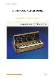
minimoog owners manual.pdf - Synth Zone
minimoog owners manual.pdf - Synth Zone
minimoog owners manual.pdf - Synth Zone
Create successful ePaper yourself
Turn your PDF publications into a flip-book with our unique Google optimized e-Paper software.
Minimoog Operation Manual<br />
back and forth with your left hand. Notice that you can reset the control by feel a<br />
detent mechanism holds it in its normal center position.<br />
11. The TUNE control (1) is used to tune up the Mini Moog oscillators to the pitch of<br />
the ensemble in which it is being used, or to its A-440 reference tone. Check to see<br />
that switch (C) is on, and notice that, when a key is depressed, the pitch moves up<br />
and down by a few tones as the TUNE control is turned through its range. Make sure<br />
the PITCH wheel is in its center position, and turn on the A-440 switch (Q). Depress<br />
an A key on the keyboard, and adjust the TUNE control so that the two A's are in<br />
tune with each other. Turn off the A-440. The other two oscillators may now be tuned<br />
to Oscillator 1 using their FREQUENCY controls.<br />
12. The GLIDE control (2) regulates the amount of portamento, or glide, heard<br />
between pitches as first one key and then another is depressed. This control is<br />
activated by turning on the GLIDE switch (R). Setting the GLIDE control at various<br />
levels, play a scale or arpeggio, first with the GLIDE switch on, then using the switch<br />
to introduce glide selectively between certain notes only. Notice that the further to the<br />
right control (2) is set, the longer it will take a tone to move from one pitch to the next.<br />
13. Finally, the KEYBOARD itself functions as a controller. It produces a control<br />
signal which varies according to the position of the key struck. If more than one key is<br />
held down, only the lowest one has effect. The control output of the KEYBOARD is<br />
permanently connected to Oscillators 1 and 2. Switch (B) couples it to Oscillator 3.<br />
Switches (K) and (L) couple it to the filter, and are discussed in the modifiers section,<br />
step 8. The KEYBOARD also produces a timing signal each time a key is depressed.<br />
This will be discussed in the modifiers section in connection with filter and loudness<br />
contour controls.<br />
mixer<br />
Audio signals produced by the three oscillators, noise source, and microphone<br />
preamplifier are combined and balanced by the Mixer section's switches and volume<br />
controls. It is this composite signal, the output of the mixer, which is then modified by<br />
the filter and loudness contour controls and appears as the audio output signal of the<br />
Mini Moog.<br />
1. The OSCILLATOR VOLUME controls (12, 13, and 14) are used to regulate the<br />
relative levels of the audio signals produced by the three oscillators. Switches (C),<br />
http://www.oldschool-sound.com Page 8


