1969 Camaro - Classic Auto Air
1969 Camaro - Classic Auto Air
1969 Camaro - Classic Auto Air

Create successful ePaper yourself
Turn your PDF publications into a flip-book with our unique Google optimized e-Paper software.
©<br />
<strong>1969</strong> <strong>Camaro</strong><br />
DOCUMENT #1-2056<br />
©2012 <strong>Classic</strong><strong>Auto</strong><strong>Air</strong> / 3.12vs.a
Congratulations...<br />
You have just purchased the highest quality, best performing<br />
A/C system ever designed for your <strong>Classic</strong> Vehicle.<br />
To obtain the high level of performance and dependability our systems are known for, please pay close attention to the<br />
following instructions. Our installation steps and procedures are derived from a long history of research and<br />
development and the combined experience achieved thru thousands of successful installations (and feedback from<br />
customers like you). Please remember that our #1 goal is that you’ll have a successful installation and a system that<br />
performs at a very high level for many years to come.<br />
Before starting, read the instructions carefully, from beginning to end, and follow the proper sequence. On the next<br />
page you’ll find a safety and general checklist that you should read before starting your installation.<br />
Again, thank you from our entire staff.<br />
www.classicautoair.com • 866.435.7801
4<br />
Check List, Pre-Installation:<br />
Before beginning the installation check the shipping box for the correct components. YOUR BOXED UNIT INCLUDES A LIST OF<br />
MAJOR COMPONENTS AND A LIST OF BAGGED PARTS. We have a 5 stage check process to make sure you have everything you’ll<br />
need.<br />
If your vehicle has been or is being modified, some procedures will need to be adjusted to fit your particular application.<br />
A basic cleaning of the engine compartment and interior before beginning will make things go more smoothly.<br />
Check condition of engine mounts. Excessive engine movement can damage hoses to A/C and/or heater.<br />
Before starting, check vehicle interior electrical functions (interior lights, radio, horn, etc). Make a note of anything that does not work as<br />
it’s supposed to. During the installation you might find the opportunity to repair or upgrade non-working or out of date components.<br />
When you’re ready to start the installation, DISCONNECT THE BATTERY FIRST.<br />
Drain the radiator. Retain the coolant and reuse, or dispose of properly.<br />
SAFETY FIRST: Wear eye protection while drilling/cutting, deburr sharp edges, and never get in a hurry or force a part.<br />
Tools: Your installation only requires the basic tools everyone has in their garage, nothing exotic or specific to A/C or Heat equipment.<br />
Procedures, During Installation:<br />
Fittings: Use one or two drops of mineral oil (supplied with your kit) on ALL rubber o-rings, threads and rear of bump for o-ring where<br />
female nut rides. Do not use thread tape or sealants.<br />
Measure twice (or more), cut once<br />
Should you have any technical questions, or feel you have defective components (or missing items), call us immediately,<br />
we will be glad to assist you. Our toll-free number is listed on every page, we’re here to help!<br />
YOU CAN NOW BEGIN THE INSTALLATION...<br />
www.classicautoair.com • 866.435.7801
5<br />
A Basic A/C Overview<br />
1<br />
Evaporator with Blower Fan In order to remove the heat from the air in the vehicle, the A/C<br />
evaporator allows the refrigerant to absorb the heat from the air passing over it. The blower fan moves cool air out into the car<br />
interior.<br />
OUTSIDE AIR<br />
2<br />
Compressor The compressor pumps and circulates the refrigerant through the system.<br />
Suction<br />
Valve<br />
Discharge<br />
Valve<br />
3<br />
4<br />
Condenser The condenser is a heat exchanger mounted at the front of the vehicle. Heat drawn out of the interior of<br />
the car is expelled here.<br />
Receiver/Drier The drier not only dries refrigerant, it also filters the refrigerant and stores it under certain<br />
operating conditions.<br />
Receiver<br />
Drier<br />
Condenser<br />
Compressor<br />
5<br />
High Pressure Switch A pressure switch is used to shut down the system if high or low pressure is<br />
detected, basically it acts as a safety switch.<br />
Firewall<br />
AIR FROM INSIDE VEHICLE<br />
Expansion Valve<br />
COOLED AIR<br />
1<br />
3<br />
SUCTION HOSE<br />
2<br />
DISCHARGE HOSE<br />
5<br />
4<br />
LIQUID HOSE<br />
POWER<br />
GROUND<br />
Evaporator Unit<br />
COLD AIR INTO VEHICLE<br />
The air conditioning system in your car is comprised of a compressor, condenser,<br />
expansion valve, receiver/drier, and evaporator. Refrigerant (also known as Freon) is<br />
compressed in the compressor and turns into a gas. In the condenser, this gas is cooled to a<br />
liquid state and travels to the expansion valve. As the liquid refrigerant goes through the<br />
expansion valve it rapidly cools in the evaporator. A fan blows over the evaporator and cools the<br />
air that blows out your vents. The receiver-drier separates gas and liquid.<br />
www.classicautoair.com • 866.435.7801 • OVERVIEW
6<br />
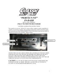
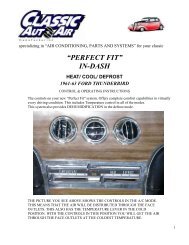
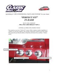
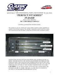
Control & Operating Instructions<br />
Your new Perfect Fit-Elite system offers complete comfort capabilities in virtually every driving condition. This<br />
includes temperature control in all of the modes. This system also provides the ability to blend the air between Face,<br />
Heat, and Defrost modes simultaneously. To illustrate the various ways you can adjust the airflow direction and<br />
temperature - we’ve provided these handy illustrations and chart to show exactly how you can adjust your Perfect<br />
Fit-Elite for maximum comfort...<br />
Left Lever Postion<br />
Distribution<br />
Compressor<br />
State<br />
FACE<br />
1 Face A/C 100%<br />
ON<br />
FAN SWITCH<br />
OFF COLD DASH<br />
DEF<br />
HI HOT FLOOR<br />
TEMP LEVER<br />
MODE LEVER<br />
The COLD/HOT positions works like any<br />
traditional adjustment lever<br />
There are 11 levels of<br />
adjustment within the<br />
range of the<br />
DASH/FLOOR lever<br />
The FAN switch<br />
works like the<br />
OEM switch, the<br />
far left position is<br />
OFF (all power to<br />
the system is OFF<br />
in this position)<br />
OFF<br />
HI<br />
COLD<br />
HOT<br />
DASH<br />
FLOOR<br />
DEF<br />
1<br />
2<br />
3<br />
4<br />
5<br />
6<br />
7<br />
8<br />
9<br />
10<br />
11<br />
FLOOR DEF<br />
2<br />
3<br />
4<br />
5<br />
Face A/C 80%<br />
Defrost 20%<br />
Face A/C 60%<br />
Defrost 40%<br />
Face A/C 40%<br />
Defrost 60%<br />
Face A/C 20%<br />
Defrost 80%<br />
6 Defrost 100% ON<br />
7<br />
8<br />
9<br />
10<br />
Floor 20%<br />
Defrost 80%<br />
Floor 40%<br />
Defrost 60%<br />
Floor 60%<br />
Defrost 40%<br />
Floor 80%<br />
Defrost 20%<br />
11 Floor 100%<br />
www.classicautoair.com • 866.435.7801
7<br />
INTERIOR<br />
COMPARTMENT<br />
Remove Glovebox, Console (optional)<br />
Radio and Bezel, and set them aside<br />
for reinstall later (see figure 1).<br />
The removal of the Original Heater<br />
Assembly can be accomplished by disconnecting three<br />
control cables. One is attached to the Heat/Defrost door (see<br />
figure 2). One is attached to the Temperature door, and one is<br />
attached to the Vent / Heat door (see figure 3). Disconnect the<br />
electrical harness from the assembly. Also remove attachment<br />
screw located in front of the air inlet (see figure 4).<br />
When retaining parts it’s a<br />
good idea to store parts in a<br />
zip lock bag, labeled with<br />
info where the parts came<br />
from and what size/type of<br />
tool is needed to reinstall. Cleaning<br />
the parts before you need to reinstall<br />
them is a good idea too.<br />
GOOD IDEA<br />
FIGURE 2<br />
FIGURE 3<br />
FIGURE 4<br />
www.classicautoair.com • 866.435.7801
8<br />
THESE ARE THE PARTS YOU WILL FIND IN BAG KIT A<br />
You will use all of these parts and hardware during the next series of installation steps.<br />
Pressure Switch<br />
(engine compartment)<br />
Ground<br />
Ground<br />
ECU<br />
Thermostat<br />
OEM Power<br />
Supply<br />
Connecting wire<br />
PN#0034-19<br />
Fan<br />
Plug<br />
Wire Harness -<br />
Power Supply<br />
PN#0105-36<br />
Blower Switch<br />
Connection<br />
Cable Integrators<br />
PN#16-2030<br />
Relay<br />
Push Nuts<br />
PN#PD156007PG<br />
Blower Switch<br />
PN#16-1050-1<br />
Two - Cable Clips<br />
PN#25-1015<br />
NOTE: Illustrations NOT shown actual size<br />
www.classicautoair.com • 866.435.7801
9<br />
Remove The Heater Control Head From The Dash.<br />
1) Remove the OEM blower switch knob. Retain the screws, you will use them<br />
again shortly. Remove the control cables and the original blower switch and set<br />
aside (these will not be reused).<br />
2) Attach the new blower switch with bracket as shown to the right, utilizing the<br />
OEM screws.<br />
OEM SCREWS<br />
3) Attach the included connecting wire to one end of the control switch arm (it<br />
will “jog” thru the hole) and the other end will be secured to the control arm pin<br />
with a push nut.<br />
This completes your blower switch installation.<br />
www classicautoair com • 866.435.7801
10<br />
Preparing the MODE EZ Cable Integrator for installation: First place a<br />
included cable clip over the ends of the EZ Integrator (as shown<br />
below). Prepare both integrators the same way. It is very important<br />
that you place the cable clips over the end of the intergrators very<br />
securly and evenly. Place the cable clip over the end, press it firmly<br />
into place (using needle-nose pliers is recommended).<br />
MODE<br />
OEM SCREW<br />
Next, attach the MODE EZ Cable Integrator to the control head as<br />
show to the right. The loop ends of the integrator wires will be<br />
secured with the a push nut.<br />
www.classicautoair.com • 866.435.7801
11<br />
Preparing the TEMP EZ Cable Integrator for installation: First place a<br />
included cable clip over the ends of the EZ Integrator (as shown<br />
below). Prepare both integrators the same way. It is very important<br />
that you place the cable clips over the end of the intergrators very<br />
securly and evenly. Place the cable clip over the end, press it firmly<br />
into place (using needle-nose pliers is recommended).<br />
Next, attach the TEMP EZ Cable Integrator to the control head as<br />
show to the right. The loop ends of the integrator wires will be<br />
secured with the a push nut.<br />
www classicautoair com • 866 435 7801
12<br />
THESE ARE THE PARTS YOU WILL FIND IN BAG KIT B<br />
You will use all of these parts and hardware during the next series of installation steps.<br />
Liquid Tube<br />
PN#0034-9<br />
Suction Tube<br />
PN#0034-10<br />
#6 and #10 O-ring<br />
Evaporator Support Brackets<br />
PN#0023-7<br />
Two <strong>Air</strong> Inlet Block Offs<br />
PN#0050-8<br />
Fresh <strong>Air</strong> Inlet Block Off<br />
PN#10-1048-2<br />
Two #10 - 16 x 3/4" Tek Screws<br />
One Bulb Clamp<br />
Six #10 - 10 x 5/8" Phillips Screws<br />
Defrost/Heat Duct Assembly<br />
PN#2-2025-2<br />
Illustrations NOT shown actual size<br />
One Male Spade Connector<br />
One Flange Nut<br />
www.classicautoair.com • 866.435.7801
13<br />
Locate the original wiring harness that supplied power to the original heater<br />
motor. Reaching thru the glove box opening pull these wires out of their<br />
grommet (see figure 6). (GM normally used a brown wire for power). On the<br />
OEM power supply wire attach a 1/4” insulated male spade connector. Within<br />
the OEM fuse box upgrade the factory HEATER fuse with a 20 amp fuse (VERY<br />
IMPORTANT).<br />
4"<br />
Looking thru the glove box door opening, locate the bottom left mounting hole<br />
in the firewall that attached the original heater motor, and follow the directions<br />
for drilling as shown below. From inside of the vehicle drill a 5/8” dia. hole for<br />
the drain tube.<br />
FIGURE 6<br />
THIS IS<br />
FROM THE INSIDE<br />
OF THE VEHICLE!<br />
3/4”<br />
5/8” drain hole<br />
You can now begin installing your <strong>Classic</strong> <strong>Air</strong> Perfect Fit Elite System.<br />
www.classicautoair.com • 866.435.7801
14<br />
Within the engine compartment area, Install a Fresh <strong>Air</strong> inlet block off over the<br />
OEM vent opening using the original bolts.<br />
COWL<br />
Remove evaporator unit from box and place on a flat work surface.<br />
Locate defrost / heat duct assembly and attach to the evaporator using two<br />
#10 - 10 x 5/8" Phillips screws (see figure 7). NOTE: Be sure that the s-clips are<br />
pushed over rear flange on evaporator.<br />
Remove Passenger and Drivers side ball louvers. Retain original hardware.<br />
Located behind the OEM astro vents louvers you will find a flex duct connected<br />
to the air inlet adapter. Remove the duct and the air inlet adapter. Attach the<br />
included block-off plates (Two PN#0047-1) over the existing holes using original<br />
hardware.<br />
Take a minute to familiarize yourself with the evaporator unit:<br />
Actuator Motor<br />
Evaporator Mouting Stud<br />
Floor/Face<br />
Vent Door<br />
Evaporator<br />
Support Bracket<br />
Holes<br />
Thermostat<br />
Blower Motor Plug<br />
FIGURE 7<br />
www.classicautoair.com • 866.435.7801
15<br />
Installing the complete evaporator unit under the dash will go much easier with<br />
the help of a friend. One person can take the unit within the car and “roll” up<br />
and under the dash while the other person can be ready at the firewall area with<br />
the included flange nut to secure the unit in place (see figure 8). Now the unit<br />
will be easy to level and secure. Leveling the unit is very important to insure<br />
proper drainage of condensation.<br />
DASH<br />
FIREWALL<br />
LEVEL<br />
TECH TIPS<br />
Be sure to align the evaporator unit level with the bottom of<br />
instrument panel (assuming the vehicle is sitting level) as shown<br />
above, but with a small degree of tilt toward the back to allow<br />
proper drain of condensation.<br />
Flange Nut attached to stud protruding<br />
thru original mounting hole<br />
FIGURE 8<br />
www.classicautoair.com • 866.435.7801
16<br />
Locate in the UPPER MOUNTING BRACKETS and attach to evaporator unit<br />
using four #10 - 10 x 5/8" Phillips screws. Attach other end to the cowling<br />
with a #10 - 16 x 3/4" Tek Screws (see figure 9). IMPORTANT NOTE: On the<br />
side of the main unit you will see several holes for mounting holes...<br />
ONLY USE THE ONES ON THE FAR LEFT AND RIGHT FOR THESE<br />
BRACKETS! Do not tap into the other holes for any reason (see figure 10).<br />
Also, use a screwdriver and hand-power and do not over-tighten so you don't<br />
strip the holes.<br />
YES<br />
#10 - 16 x 3/4" Tek Screw<br />
FIGURE 10<br />
NO!<br />
YES<br />
FIGURE 9<br />
#10 x 5/8"<br />
Screws<br />
#10 x 5/8"<br />
Screws<br />
www.classicautoair.com • 866.435.7801
17<br />
Install liquid line onto the Expansion valve (TXV) as<br />
shown. Use #6 o-ring and (2) drops of mineral oil on<br />
the o-ring and tighten securely.<br />
Install Suction Tube to the outlet on the unit as<br />
shown. Use #10 o-ring and (2) drops of mineral oil<br />
on the o-ring and tighten securely.<br />
Locate Sensing Coil attached to Expansion valve<br />
(TXV) and utilizing Bulb Clamp, attach to the Suction<br />
Tube.<br />
CAUTION: THE SYSTEM WILL NOT FUNCTION<br />
PROPERLY IF THE SENSING COIL IS NOT<br />
CLAMPED IN THE CORRECT POSITION. SEE<br />
PICTURE.<br />
Wrap Suction Tube and Sensing Coil with the<br />
refrigerant tape provided. Be sure that all of the<br />
exposed metal is covered.<br />
O-RING<br />
O-RING<br />
TECH TIPS<br />
Reminder...<br />
Use two<br />
wrenches to<br />
tighten o-ring<br />
fittings<br />
BULB CLAMP<br />
NO! NO!<br />
YES<br />
NO!<br />
Suction Tube<br />
www.classicautoair.com • 866.435.7801
18<br />
THESE ARE THE PARTS YOU WILL FIND IN BAG KIT C<br />
You will use all of these parts and hardware during the next series of installation steps.<br />
<br />
<br />
<br />
<br />
<br />
<br />
<br />
<br />
Illustrations NOT shown actual size<br />
866.435.7801
19<br />
A/C<br />
Tubes<br />
Heater<br />
Tubes<br />
It may be necessary to manipulate<br />
the tubes slightly to get proper<br />
fittment thru the block-off plate<br />
In Bag Kit C you’ll find the firewall block off. Install this over the hose connections<br />
coming thru the firewall within the engine compartment. Attach with six #10 - 16 x 3/4"<br />
Tek screws. Seal around the tubes with the included refrigerant tape. This will keep<br />
unwanted moisture and debris from entering thru the firewall... so seal<br />
carefully and thoroughly.<br />
IMPORTANT NOTICE <strong>Classic</strong> <strong>Auto</strong> <strong>Air</strong> has done extensive testing on the<br />
correct method to install the water valve in order to get a repeatable and progressive<br />
temperature control. The water valve must be installed per these instructions!....<br />
The lower connection on the tubes coming thru the block off assembly is going to be<br />
routed to the water outlet on the intake manifold. Attach your hose with cable clamps<br />
on both ends and route where it will not intefere with linkage or come in contact with<br />
exhaust manifolds or headers.<br />
The upper port coming thru the firewall will be routed to and thru your new your<br />
electronic water valve (the water valve is marked for easy installation). First Attach<br />
a 6” piece of 5/8” dia. heater hose with the supplied worm gear clamp. Attach<br />
to the inlet side of the water valve using another supplied hose clamp.<br />
Attach a heater hose from the outlet side of the electronic water valve<br />
and route to the connection on the water pump.<br />
HEATER CORE<br />
WATER PUMP<br />
Insert a 6" piece of the clear, 1/2" drain tube we included<br />
through the hole previously drilled and attach over the<br />
drain nipple. Seal around tube with refrigerant tape.<br />
www.classicautoair.com • 866.435.7801
20<br />
THESE ARE THE PARTS YOU WILL FIND IN BAG KIT D<br />
You will use all of these parts and hardware during the next series of installation steps.<br />
The ECU will be shipped in it’s own box,<br />
along with the calibration key.<br />
WATER VALVE<br />
CONTROL<br />
POWER<br />
FACE/FLOOR<br />
DEFROST<br />
Four #10 - 16 x 3/4" Tek Screws<br />
Yellow<br />
Orange<br />
Blue<br />
Illustrations NOT shown actual size<br />
Wire Harness System
21<br />
We’ve included enough wire length to allow you to mount the ECU in a variety<br />
of places. It is very important that you mount this in a place where it will stay dry<br />
and that vibration is at a minimum. Also make sure that where ever you mount it<br />
does not interfere with any moving controls or cables. We recommend<br />
mounting it just above the right hand side of the main unit using the included<br />
tek-screws. IMPORTANT! DON’T MOUNT THE ECU PERMANENTLY JUST<br />
YET. THAT CAN BE DONE AFTER YOU CALIBRATE THE UNIT.<br />
In Bag Kit D you will find three wiring harnesses with connections at each end.<br />
Plug the harness with YELLOW band into the YELLOW ECU port and the other<br />
end into the servo motor on the main unit (motor is marked with YELLOW<br />
INDICATOR). Repeat this process for the other two harnesses, following the<br />
color coding indicated on cables and ports. Attach cable in the engine<br />
compartment to the electronic water valve (see figure 12). Using one of the CAP<br />
PLUGS provided, slot it and install over the heater hose/cable.<br />
Figure 12<br />
NOTE: The GREEN harness connection will be made from the harness you<br />
previously installed, just plug the loose connection in the CONTROL<br />
port on the ECU.<br />
WATER VALVE<br />
FIREWALL<br />
CONTROL<br />
POWER<br />
FACE/FLOOR<br />
DEFROST<br />
www.classicautoair.com • 866.435.7801
22<br />
Wiring Diagram/Overview<br />
To 12V Power Supply<br />
g<br />
Orange Harness<br />
Electronic Water Valve<br />
Red/White Wire<br />
Compressor<br />
Blower Switch<br />
Green Harness<br />
Blue Wires<br />
Ground<br />
Pressure Switch<br />
White Wire<br />
ECU<br />
Ground<br />
Cable Integrators<br />
Yellow Harness<br />
Servo for Face/Floor Ducts<br />
Blue Harness<br />
Thermostat<br />
Blue Wire<br />
Relay<br />
Red Wire<br />
Blue Wire<br />
Servo for Defrost Ducts<br />
Evaporator<br />
Blue Wire<br />
Ground<br />
REMINDER: BE SURE THAT THE WIRING HARNESS DOES NOT INTERFERE WITH THE OPERATION OF ANY CONTROLS.
23<br />
TEMPORARILY RECONNECT THE BATTERY AT THIS TIME.<br />
YOU CAN NOW CALIBRATE YOUR UNIT.<br />
CALIBRATION: Before we boxed and shipped your unit, we tested and<br />
calibrated it to factory specifications to make sure it is capable of operating at<br />
maximum efficiency. However, the unit must still be calibrated to your specific<br />
vehicle and controls. This is an easy process that will only take a few minutes.<br />
OFF<br />
COLD<br />
DASH<br />
OFF COLD DASH<br />
OFF COLD DASH<br />
DEF DEF DEF<br />
As you follow thru these steps you’ll be able to hear the motors working on your<br />
unit. If for any reason your unit does not calibrate properly the first time, just turn<br />
off the unit and rerun the setup process.<br />
WATER VALVE<br />
WATER VALVE<br />
HI<br />
A<br />
HOT<br />
FLOOR<br />
HI<br />
HOT<br />
FLOOR<br />
1) Insert Calibration Key<br />
2) Move MODE control to (FLOOR) and<br />
TEMP control to (COLD)<br />
3) Power Up Board (turn fan control to MEDIUM) the<br />
LED comes ON<br />
4) After 1 second the LED turns OFF<br />
5) After 1 second the LED turns ON<br />
HI<br />
HOT<br />
FLOOR<br />
QUICK<br />
NOTE<br />
CONTROL<br />
POWER FACE/FLOOR DEFROST<br />
Calibration Key<br />
CONTROL<br />
Calibration Key<br />
POWER FACE/FLOOR DEFROST<br />
Disconnecting the power (i.e. battery) will not cause your ECU to<br />
lose it’s settings. AFTER CALIBRATING, REMOVE KEY AND<br />
STORE IN A SAFE, DRY PLACE - ALONG WITH THIS PAGE.<br />
B<br />
C<br />
6) Move MODE control to (DASH)<br />
7) After 1 second the LED turns OFF<br />
8) After 1 second the LED turns ON<br />
9) Move TEMP control to (HOT)<br />
10) After 1 second the LED turns OFF<br />
11) After 1 second the LED turns ON<br />
12) The motor calibration starts, one way<br />
then the other, then the doors set<br />
to midpoint<br />
13) LED turns OFF<br />
14) Turn power to OFF<br />
15) Remove and store calibration key<br />
www.classicautoair.com • 866.435.7801
24<br />
THESE ARE THE PARTS YOU WILL FIND IN BAG KITS E, F, and G<br />
You will use all of these parts and hardware during the next series of installation steps.<br />
Bag E Bag F Bag G<br />
Louver Adaptor<br />
PN#2-1056-3<br />
Louver Adaptor<br />
PN#2-1056-2<br />
Center Dash Vent<br />
PN#2-1056-1<br />
Two Defrost Diffuser<br />
PN#2-1054-2<br />
Two Duct Hoses, 2" I.D.<br />
Two Duct Hoses, 2" I.D.<br />
Two Duct Hoses, 2" I.D.<br />
Face/Floor Assembly<br />
PN#2-2025-1<br />
Two #10 - 16 x 3/4" Tek Screws<br />
Four Zip-Ties<br />
Illustrations NOT shown actual size<br />
Four Zip-Ties<br />
Four Zip-Ties<br />
www.classicautoair.com • 866.435.7801
25<br />
Bag Kit E. The following steps are for left and right Defrost Diffusers...<br />
Locate and route the duct hoses from the defrost/heat duct assembly upward<br />
toward defrost vents. Attach the flex hose to the defrost defuser using zip-ties.<br />
The other end of the duct hose is installed over the defrost/heat duct assembly<br />
outlets on main unit (see figures 13 and 14).<br />
The face/floor assembly comes preinstalled with s-clips which allow you to<br />
install it onto the evaporator unit quickly and securely (see figure 15).<br />
TOP OF DASH<br />
FIGURE 14<br />
FIGURE 13<br />
Push defrost adaptors onto<br />
lip of dash tab (below defrost vents,<br />
inside of dash), S-clips (already installed)<br />
will hold the adaptors securely<br />
FIGURE 15<br />
www.classicautoair.com • 866.435.7801
26<br />
Attach louver adaptors to the back side of OEM louvers, both sides. S-Clips will<br />
hold them in place. Square adaptor for drivers side, round for passenger.<br />
Route supplied flex hoses as shown below.<br />
Take your time and route them so they<br />
don’t become kinked or torn.<br />
GOOD IDEA<br />
To defrost defuser adaptors<br />
The smoother the route of the flex hoses<br />
the better the airflow.<br />
During installation of the hoses be<br />
aware of the eventual movement of<br />
the wiper arm components.<br />
Drivers Side<br />
OEM Housing<br />
OEM VENT<br />
Adaptor<br />
OEM VENT<br />
Passenger<br />
OEM Housing<br />
Adaptor<br />
www.classicautoair.com • 866.435.7801
27<br />
Bag Kit G: Remove Dash Pad and place on bench.<br />
Locate the templates we’ve included, cut out the<br />
templates (piece together to make one piece) and tape<br />
to the dash pad.<br />
Carefully cut dash pad along the opening in the<br />
template.<br />
Locate in the hardware sack kit the center louver and<br />
(2) #10 x ¾‘tek screws.<br />
Place louver over the trimmed dash pad and push<br />
down so that the edge of the louver and dash pad are<br />
equal.<br />
Attach louver using (2) #10 screws.<br />
The center louver will be<br />
held in place with an<br />
included bracket and two<br />
Tek screws. The flex hoses<br />
will be inserted into the<br />
back of the louver and be<br />
held in place.<br />
HOSE<br />
www.classicautoair.com • 866.435.7801
28<br />
You can reinstall the glove box at this time, and any other interior<br />
components that we’re removed.<br />
This completes the interior portion of the PERFECT FIT-ELITE<br />
installation process. This is a good time to make a final check that all the<br />
controls still move freely and that nothing is loose or hanging down.<br />
The interior of your car should look pretty much the same as before you<br />
started (or better). Plus you probably got to know the underside of your<br />
dash a lot better and might even have repaired or upgraded components<br />
that needed attention.<br />
Good Job... Let's move on to the major components within the<br />
engine compartment....<br />
If you have any questions before you move<br />
on the final phase of this installation, call us.<br />
888.791.6384<br />
www.classicautoair.com • 866.435.7801
29<br />
THESE ARE THE PARTS YOU WILL NEED FOR THE<br />
ENGINE COMPARTMENT INSTALLATION<br />
You’ll find all of these parts within the main box<br />
Drier Bracket<br />
Drier<br />
Splice and<br />
Bullet Connector<br />
Top Condenser Bracket<br />
PN#0049-50<br />
Bottom Condenser Brackets<br />
PN#0049-51<br />
Condenser<br />
PN#11-1089<br />
Core Support Bracket<br />
PN#0049-62<br />
Core Support Bracket<br />
PN#19-151<br />
Eleven #10 - 20x1/4" Screws<br />
Six #10 - 16 x 3/4" Tek Screws<br />
Pressure Switch and harness,<br />
Bag of O-rings and Mineral Oil Tube<br />
Liquid<br />
Tube<br />
(condenser<br />
to drier)<br />
Discharge<br />
Tube<br />
(condenser<br />
to rad support)<br />
Liquid<br />
Tube<br />
(drier to<br />
rad support)<br />
#6 5/16" Liquid Hose<br />
#8 13/32" Discharge Hose<br />
#10 1/2" Suction Hose<br />
Three Refrigerant Hoses<br />
www.classicautoair.com • 866.435.7801
30<br />
DRIER AND CONDENSER PREPARATION. You can perform most of the<br />
following steps on a clean flat surface like a workbench. Lay the condenser<br />
down so that both hose connections are on the left side (the larger connection<br />
will be on top). The drier is conveniently mounted on the left hand side of the<br />
condenser. First insert the drier into the drier mounting bracket (it’s basically a<br />
sleeve for the drier). Attach the drier liquid tube to the drier and also to the<br />
connection on the condenser (tighten connections at either<br />
end using supplied o-rings on both ends and a few drops of<br />
mineral oil to each o-ring). With these two components<br />
combined it will easy to find the correct place to attach the<br />
drier bracket to the condenser with the included #10-20 x<br />
1/4” screws (attach drier and bracket from the front of the<br />
condenser).<br />
Two<br />
#10 - 20x1/4"<br />
Screws<br />
Fit brackets with #10 - 20x1/4" Screws, fitted loosely into the<br />
top two holes of the condenser, both sides<br />
PRESSURE SWITCH: Screw the high-pressure switch into<br />
the port on the top of the drier. Go ahead and plug the<br />
pressure switch harness into the switch at this time (black<br />
electrical boot with two long white wires).<br />
Pressure<br />
Switch<br />
BRACKETS: Install the upper condenser bracket using four<br />
#10 - 20 x 1/4“ screws in the top two holes on each side.<br />
Next, attach the lower brackets using the bottom two holes,<br />
with the same size screws. These brackets have a bend that<br />
will face away from you.<br />
TECH TIPS<br />
Reminder...<br />
Use two<br />
wrenches to<br />
tighten o-ring<br />
fittingsTECH TIPS<br />
Fit brackets with #10 - 20x1/4" Screws, fitted loosely into the<br />
top two holes of the condenser, both sides<br />
You can easily find the<br />
correct position for mounting<br />
the drier to the condenser by<br />
using the drier liquid tube as<br />
a gauge.<br />
www.classicautoair.com • 866.435.7801
31<br />
Remove the hood latch assembly. Retain original<br />
hardware. Slide condenser assembly down in front of the<br />
radiator.<br />
Two #10 - 16 x 3/4" Tek Screws<br />
Locate condenser in the center of<br />
the radiator. Attach top condenser<br />
brackets to the bulkhead using (2)<br />
#10 Tek screws.<br />
Discharge Tube<br />
Located behind the air damn and at<br />
the lower radiator bulkhead, attach<br />
the lower condenser brackets using<br />
(2) # 10 Tek screws.<br />
Reinstall hood latch assembly using<br />
original hardware.<br />
Liquid Tube<br />
Locate the Liquid tube, Discharge tube, (1) #6 o-ring,<br />
and (1) #8 o-ring. Attach Liquid tube to the drier using the #6<br />
o-ring and a few drops of mineral oil. Attach Discharge tube to the<br />
condenser using #8 o-ring and a few drops of mineral oil.<br />
Two #10 - 16 x 3/4" Tek Screws<br />
(upward from bottom)<br />
Locate the tube support bracket, the tube clamp, and (2)<br />
#10 x ¾” tek screws, and (1) #10 x ½” hex head screw.<br />
Attach the support bracket to the radiator bulkhead using (2) #10 x<br />
¾” tek screws.<br />
Attach liquid and discharge tubes using the tube clamp, using (1)<br />
#10 x ½” screw.<br />
#10 - 20x1/4"<br />
Screw<br />
Two #10 - 16x3/4"<br />
Tek Screws<br />
www.classicautoair.com • 866.435.7801
32<br />
Time to install the compressor kit. Included in your box is a premium<br />
compressor kit with all the parts you’ll need to install the compressor. This kit<br />
includes instructions specifically written for your engine. Once you’ve installed<br />
the complete compressor kit, continue on to connecting the hoses.<br />
#6 Hose<br />
#8 Hose<br />
#10 Hose<br />
COMPLETE<br />
COMPRESSOR<br />
KIT<br />
CONNECTING THE HOSES:<br />
1) Attach the #8 Discharge Hose (13/32") from the connection under the core<br />
support and route to the compressor. Tighten fittings using o-rings and mineral<br />
oil provided.<br />
2) Attach the #6 liquid hose (5/16") from the connection under the core support<br />
connection at the firewall on the evaporator unit (see figure 41). Tighten fittings<br />
using o-rings and mineral oil supplied in kit.<br />
Passenger Side Compresssor<br />
#6 Hose<br />
#8 Hose<br />
#10 Hose<br />
3) Attach the #10 suction hose (1/2”) to the compressor and route as mentioned<br />
above. Tighten fittings using o-rings and mineral oil supplied in the kit.<br />
Drivers Side Compresssor<br />
www.classicautoair.com • 866.435.7801
33<br />
Connect the pressure switch by first connecting one wire to the connection on<br />
the compressor, and the other wire will be routed along with the liquid hose and<br />
connected to the blue lead you put thru the firewall during the interior installation<br />
(for attachment route. We’ve included a bullet and slice connector to make these<br />
connections, use a crimp tool to secure these properly.<br />
FINAL STEPS: Take a look around at your installation and check all fittings and<br />
bolts for tightness, check the heater hose clamps for tightness, and make sure<br />
nothing is routed in a way to obstruct any moving parts. You can refill the<br />
radiator and reconnect the battery at this time.<br />
WAY TO GO! You’ve just completed the installation of your new A/C system.<br />
The very final step is to fully charge and test your new system.<br />
On the next page you’ll find specifications for proper final preparation<br />
for your A/C technician.<br />
www.classicautoair.com • 866.435.7801
34<br />
New A/C System Preparation<br />
Please read thru these procedures before completing this new A/C system charging<br />
operation. A licensed A/C technician should be utilized for these procedures to insure that<br />
your new system will perform at it’s peak, and that your compressor will not be damaged.<br />
Centerline of the Oil Plug<br />
90˚<br />
90˚<br />
1) Your radiator/cooling system is an integral part of your new system. Please insure that you<br />
have a 50/50 mix of distilled water and antifreeze. The heater coil MUST be purged<br />
(cycle heater control valve) to make sure no water, without antifreeze, is in the heater coil<br />
before you charge the A/C system.<br />
2) Evacuate the system for 45 minutes (minimum).<br />
3) Your new compressor MUST be hand-turned 15-20 revolutions before and after<br />
charging with liquid. Failure to do this may cause the reed valves to become damaged (this<br />
damage is NOT covered by your warranty).<br />
4) Your new system requires 134a refrigerant. It will require 1.5 lbs (or 24 oz).<br />
5) Your new compressor comes charged with oil - NO additional oil is needed.<br />
6) Insure that the new belt is tight.<br />
7) DO NOT CHARGE SYSTEM WITH LIQUID WHILE THE ENGINE IS RUNNING!<br />
RECOMMENDED TEST CONDITIONS: (After system has been fully charged and tested for basic<br />
operation)<br />
• Determine the temperature outside of the car<br />
• Connect gauges or service equipment to high/low charging ports<br />
• Place blower fan switch on medium<br />
• Close all doors and windows on vehicle<br />
• Place shop fan directly in front of condenser<br />
• Run engine idle up to approx. 1500 rpm<br />
ACCEPTABLE OPERATING PRESSURE RANGES:<br />
1. HIGH-SIDE PRESSURES (150-250 PSI)<br />
2. LOW-SIDE PRESSURES (15-25 PSI in a steady state)<br />
Readings above are based on an ambient temperature of 90˚ with an adequate airflow on condenser<br />
CAUTION! When mounting your compressor<br />
and/or adjusting the belt, use caution not to tilt the<br />
compressor up to or more than 90˚ off the<br />
centerline of the oil fill plug. This can cause<br />
compressor failure.<br />
Do not tilt, shake or turn<br />
refrigerant can upside-down<br />
OR use a charging station to<br />
install refrigerant while the<br />
engine is running. Doing so will<br />
direct liquid refrigerant into the<br />
compressor piston chamber, causing damage to<br />
reed valves and/or pistons and/or other components, as<br />
well as potentially seizing the compressor. Allow a<br />
minimum of 30 minutes for liquid to "boil off.” You must<br />
hand turn the compressor hub (not the pulley) a minimum<br />
of 15 complete revolutions prior to starting the engine<br />
with the clutch engaged.<br />
www.classicautoair.com • 866.435.7801
35<br />
Trouble Shooting Your <strong>Classic</strong> <strong>Auto</strong> <strong>Air</strong> A/C System<br />
PROBLEM: system is not cooling properly<br />
ISSUE: cold at idle, warmer when raising engine RPM’s<br />
Make sure the Water Valve is positioned correctly<br />
The water valve is a directional valve and should be installed with the arrow pointing<br />
towards the water pump, it should be connected to the heater hose that runs from the<br />
heater core to the water pump. If the water valve is connected to the incorrect hose it<br />
allows water to circulate through the system via the heater core over powering the<br />
cooling effect of the A/C coil, (normally the air conditioning is functioning properly).<br />
Step 1: Check placement of the water valve, correct if needed. (In some cases<br />
changing the location of the water valve may not fix the above problem.) Continue to<br />
next step.<br />
Step2 If changing the location of the water valve does not rectify the issue, then<br />
possibly the water valve is permenatly damaged and may need to be replaced. To<br />
check the integrity of the water valve completely remove the water hoses for the<br />
heater core and “loop” together. (This will remove the heater system completely from<br />
the possibilities) If the system now cools, replace the water valve<br />
Verify Adequate <strong>Air</strong> Flow to Condenser<br />
For an air condiitiong system to function properly there has to be adequate airflow<br />
across the condenser. The function of the condenser is to disapate heat, without<br />
proper airflow your system will not cool correctly in the cabin of your vehicle.<br />
Step 1: connect gauges to a/c hoses. The pressures should be: with the ambient<br />
temp is 90, low side pressures should be between 8-25 psi, high side pressures<br />
should be between 160-260psi<br />
Step 2: IF the low side pressures are normal and the high side pressures are high<br />
then there might be an airflow issue, continue to next step.<br />
To test air flow to Condenser do the following three tests:<br />
1. Place a piece of paper on the condenser with the car in idle and see if paper is<br />
held in place.<br />
2. With car in idle, attach gages, and place a large capacity fan in front of the<br />
condenser. What happens to the pressures?<br />
3. With car still in idle and gages attached, pour water down the front of the<br />
condenser. What happens to the pressures?<br />
If the paper is held in place you are at least getting some air flow. If the high side<br />
decreases during test 2 & 3 then your condenser is not getting enough air which is<br />
causing your system to not cool properly. To correct this issue you will need a more<br />
powerful mechanical fan.<br />
Step 3: Confirm correct Refrigerant charge in System<br />
All of our systems should be charged with 24oz or 1.8lbs of R134 Refrigerant only. If<br />
overcharged you will need to evacuate the system and recharge with the correct<br />
amount.*<br />
What measurements mean:<br />
Low Temp and High Pressure seem to be equal...<br />
You have a malfunctioning expansion valve that is stuck open.<br />
High Side is extremely high and Low Side is extremely low (possibly into<br />
vacuum)...<br />
There is a blockage in the system. Remove hoses and blow compressed air through in<br />
both directions. If pressures don’t change its possible that your expansion valve is<br />
stuck closed and would have to be replaced.<br />
*Compressor Concerns:<br />
This is often misdiagnosed as a problem for the system not cooling properly. If you<br />
have a noisy compressor it is due to improper charging of refrigerant. An overcharged<br />
(more than 24oz or 1.8lbs R134) compressor can cause rattling. If charged with pure<br />
liquid there is a high probability you have bent reed valves that are causing tapping<br />
sound.<br />
www.classicautoair.com • 866.435.7801
36<br />
TROUBLESHOOTING GUIDE<br />
TEST CONDITIONS USED TO DETERMINE SYSTEM OPERATION<br />
(THESE TEST CONDITIONS WILL SIMULATE THE AFFECT OF DRIVING THE VEHICLE AND<br />
GIVE THE TECHNICIAN THE THREE CRITICAL READINGS THAT THEY WILL NEED TO<br />
DIAGNOSE ANY POTENTIAL PROBLEMS).<br />
B. CONNECT GAUGES OR SERVICE EQUIPMENT TO HIGH/LOW<br />
CHARGING PORTS.<br />
C. PLACE BLOWER FAN SWITCH ON MEDIUM.<br />
D. CLOSE ALL DOORS AND WINDOWS ON VEHICLE.<br />
E. PLACE SHOP FAN IN FRONT OF CONDENSER.<br />
F. RUN ENGINE IDLE UP TO 1500 RPM.<br />
ACCEPTABLE OPERATING PRESSURE RANGES (R134A TYPE)<br />
1. HIGH-SIDE PRESSURES ( 160-250 PSI ) *Note- general rule of thumb is<br />
two times the ambient (daytime) temperature, plus 15-20%.<br />
2. LOW-SIDE PRESSURES ( 06-22 PSI in a steady state).<br />
CHARGE AS FOLLOWS: R134A = 24 OZ.<br />
NO ADDITIONAL OIL IS NECESSARY IN OUR NEW COMPRESSORS.<br />
TYPICAL PROBLEMS ENCOUNTERED IN CHARGING SYSTEMS<br />
NOISY COMPRESSOR. A noisy compressor is generally caused by charging a<br />
compressor with liquid or overcharging<br />
A. If the system is overcharged both gauges will read abnormally high readings.<br />
This is causing a feedback pressure on the compressor causing it to rattle or<br />
shake from the increased cylinder head pressures. System must be evacuated<br />
and re-charged to exact weight specifications.<br />
B. Heater control valve installation - Installing the heater control valve in the<br />
incorrect hose. Usually when this occurs the system will cool at idle then start<br />
to warm up when raising the RPM’s of the motor. THE HEATER CONTROL IS<br />
A DIRECTIONAL VALVE; MAKE SURE THE WATER FLOW IS WITH THE<br />
DIRECTION OF THE ARROW. As the engine heats up that water transfers the<br />
heat to the coil, thus overpowering the a/c coil. A leaking or faulty valve will<br />
have a more pronounced affect on the unit’s cooling ability. Installing the valve<br />
improperly (such as having the flow reversed) will also allow water to flow<br />
through, thus inhibiting cooling. Check for heat transfer by disconnecting<br />
hoses from the system completely. By running down the road with the hoses<br />
looped backed through the motor, you eliminate the possibility of heat transfer<br />
to the unit.<br />
C. Evaporator freezing - Freezing can occur both externally and internally on<br />
an evaporator core. External freeze up occurs when the coil cannot effectively<br />
displace the condensation on the outside fins and the water forms ice (the<br />
evaporator core resembles a block of solid ice), it restricts the flow of air that<br />
can pass through it, which gives the illusion of the air not functioning. The<br />
common cause of external freezing is the setting of the thermostat and the<br />
presence of high humidity in the passenger compartment. All door and<br />
window seals should be checked in the event of constant freeze-up. A<br />
thermostat is provided with all units to control the cycling of the compressor.<br />
D. Internal freeze up occurs when there is too much moisture inside the<br />
system. The symptoms of internal freeze up often surface after extended<br />
highway driving. The volume of air stays constant, but the temperature of the<br />
air gradually rises. When this freezing occurs the low side pressure will drop,<br />
eventually going into a vacuum. At this point, the system should be checked by<br />
a professional who will evacuate the system and the drier will have to be<br />
changed.<br />
E. Inadequate airflow to condenser - The condenser works best in front of<br />
the radiator with a large supply of fresh air. Abnormally high pressures will<br />
result from improper airflow. Check the airflow requirements by placing a large<br />
capacity fan in front of the condenser and running cool water over the surface.<br />
If the pressures drop significantly, this will indicate the need for better airflow.<br />
F. Incorrect or inadequate condenser capacity - Incorrect condenser<br />
capacity will cause abnormally high head pressures. A quick test that can be<br />
performed is to run cool water over the condenser while the system is<br />
operating, if the pressures decrease significantly, it is likely a airflow or<br />
capacity problem.<br />
G. Expansion valve failure - An expansion valve failure is generally caused by<br />
dirt or debris entering the system during assembly. If an expansion valve fails<br />
it will be indicated by abnormal gauge readings. A valve that is blocked will be<br />
indicated by high side that is unusually high, while the low side will be<br />
www.classicautoair.com • 866.435.7801
INSTRUMENT OPENING<br />
38
40<br />
BOTTOM EDGE OF PAD<br />
CUT OUT