ITA Technical Catalogue
ITA Technical Catalogue
ITA Technical Catalogue
Create successful ePaper yourself
Turn your PDF publications into a flip-book with our unique Google optimized e-Paper software.
Intra-Automation <strong>ITA</strong> magnetically controlled liquid level indicator <strong>Technical</strong> catalogue<br />
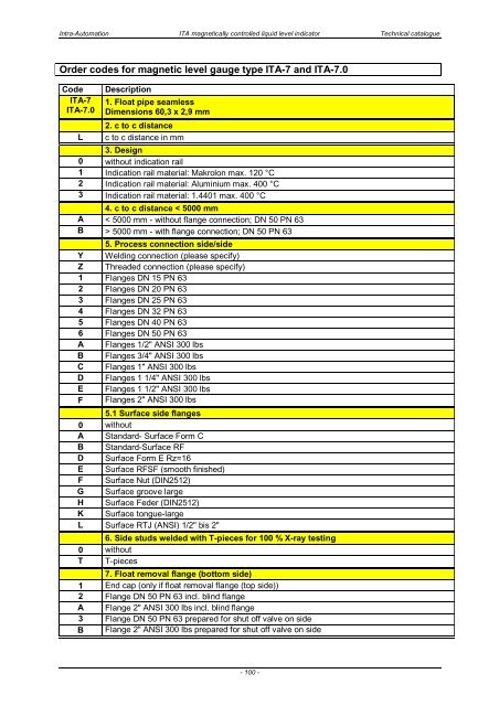
Order codes for magnetic level gauge type <strong>ITA</strong>-7 and <strong>ITA</strong>-7.0<br />
Code<br />
<strong>ITA</strong>-7<br />
<strong>ITA</strong>-7.0<br />
L<br />
Description<br />
1. Float pipe seamless<br />
Dimensions 60,3 x 2,9 mm<br />
2. c to c distance<br />
c to c distance in mm<br />
3. Design<br />
0 without indication rail<br />
1 Indication rail material: Makrolon max. 120 °C<br />
2 Indication rail material: Aluminium max. 400 °C<br />
3 Indication rail material: 1.4401 max. 400 °C<br />
4. c to c distance < 5000 mm<br />
A < 5000 mm - without flange connection; DN 50 PN 63<br />
B > 5000 mm - with flange connection; DN 50 PN 63<br />
5. Process connection side/side<br />
Y Welding connection (please specify)<br />
Z Threaded connection (please specify)<br />
1 Flanges DN 15 PN 63<br />
2 Flanges DN 20 PN 63<br />
3 Flanges DN 25 PN 63<br />
4 Flanges DN 32 PN 63<br />
5 Flanges DN 40 PN 63<br />
6 Flanges DN 50 PN 63<br />
A Flanges 1/2" ANSI 300 lbs<br />
B Flanges 3/4" ANSI 300 lbs<br />
C Flanges 1" ANSI 300 lbs<br />
D Flanges 1 1/4" ANSI 300 lbs<br />
E Flanges 1 1/2" ANSI 300 lbs<br />
F Flanges 2" ANSI 300 lbs<br />
5.1 Surface side flanges<br />
0 without<br />
A Standard- Surface Form C<br />
B Standard-Surface RF<br />
D Surface Form E Rz=16<br />
E Surface RFSF (smooth finished)<br />
F Surface Nut (DIN2512)<br />
G Surface groove large<br />
H Surface Feder (DIN2512)<br />
K Surface tongue-large<br />
L Surface RTJ (ANSI) 1/2" bis 2"<br />
6. Side studs welded with T-pieces for 100 % X-ray testing<br />
0 without<br />
T T-pieces<br />
7. Float removal flange (bottom side)<br />
1 End cap (only if float removal flange (top side))<br />
2 Flange DN 50 PN 63 incl. blind flange<br />
A Flange 2" ANSI 300 lbs incl. blind flange<br />
3 Flange DN 50 PN 63 prepared for shut off valve on side<br />
B Flange 2" ANSI 300 lbs prepared for shut off valve on side<br />
- 100 -


