ITA Technical Catalogue
ITA Technical Catalogue
ITA Technical Catalogue

Create successful ePaper yourself
Turn your PDF publications into a flip-book with our unique Google optimized e-Paper software.
Intra-Automation <strong>ITA</strong> magnetically controlled liquid level indicator <strong>Technical</strong> catalogue<br />
5. Special constructions<br />
5.1 <strong>ITA</strong>-T1S Continuous level sensing element<br />
<strong>Technical</strong> information<br />
<strong>ITA</strong>-T1S<br />
Special features<br />
Introduction<br />
- simple and rugged design<br />
- reliable performance in liquids with densities of <br />
0,5 kg/dm³<br />
- short mounting depth 300 mm (11.81”),<br />
therefore suitable for small vessels<br />
- indicating length up to 3000 mm (118”)<br />
- resistant to pressures of 40 bar (580 psi g) and<br />
temperatures of 130 °C (266 °F)<br />
- housing of cast aluminium or stainless steel in<br />
IP65 equivalent to NEMA 4 and NEMA 4x<br />
enclosure<br />
- wide variety of material combinations<br />
- various plastic coatings available for all wetted<br />
parts<br />
- 4...20 mA or Hart protocol 4...20 mA output via<br />
the signal conditioner<br />
Intra-Automation does not limit you with the standard<br />
designs catalogued here. Our experienced<br />
engineering staff, with extensive research and<br />
development capabilities, will customize liquid level<br />
indicators to meet your specific requirements.<br />
Modifications regarding the variety of mountings,<br />
exotic materials and float configurations provide<br />
compatibility for most liquid media, various tank<br />
temperatures and pressures, as well as liquids with<br />
a broad range of specific gravities.<br />
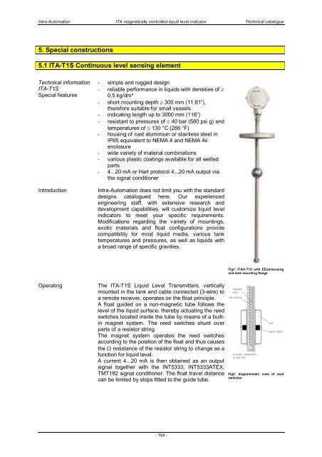
Fig1: <strong>ITA</strong>-T1S with EExd-housing<br />
and tank mounting flange<br />
Operating<br />
The <strong>ITA</strong>-T1S Liquid Level Transmitters, vertically<br />
mounted in the tank and cable connected (3-wire) to<br />
a remote receiver, operates on the float principle.<br />
A float guided on a non-magnetic tube follows the<br />
level of the liquid surface, thereby actuating the reed<br />
switches located inside the tube by means of a builtin<br />
magnet system. The reed switches shunt over<br />
parts of a resistor string.<br />
The magnet system operates the reed switches<br />
according to the position of the float and thus causes<br />
the resistance of the resistor string to change as a<br />
function for liquid level.<br />
A current 4...20 mA is then obtained as an output<br />
signal together with the INT5333; INT5333ATEX;<br />
TMT182 signal conditioner. The float travel distance<br />
can be limited by stops fitted to the guide tube.<br />
Fig2: diagrammatic view of reed<br />
switches<br />
- 194 -