ITA Technical Catalogue
ITA Technical Catalogue
ITA Technical Catalogue

You also want an ePaper? Increase the reach of your titles
YUMPU automatically turns print PDFs into web optimized ePapers that Google loves.
Intra-Automation <strong>ITA</strong> magnetically controlled liquid level indicator <strong>Technical</strong> catalogue<br />
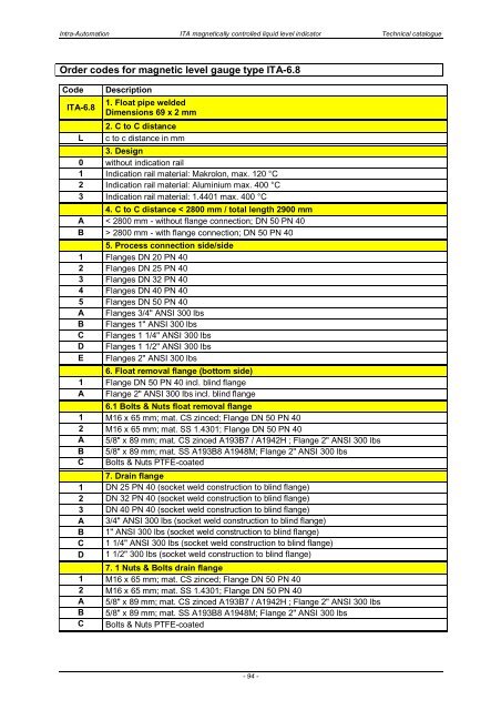
Order codes for magnetic level gauge type <strong>ITA</strong>-6.8<br />
Code<br />
<strong>ITA</strong>-6.8<br />
L<br />
Description<br />
1. Float pipe welded<br />
Dimensions 69 x 2 mm<br />
2. C to C distance<br />
c to c distance in mm<br />
3. Design<br />
0 without indication rail<br />
1 Indication rail material: Makrolon, max. 120 °C<br />
2 Indication rail material: Aluminium max. 400 °C<br />
3 Indication rail material: 1.4401 max. 400 °C<br />
4. C to C distance < 2800 mm / total length 2900 mm<br />
A < 2800 mm - without flange connection; DN 50 PN 40<br />
B > 2800 mm - with flange connection; DN 50 PN 40<br />
5. Process connection side/side<br />
1 Flanges DN 20 PN 40<br />
2 Flanges DN 25 PN 40<br />
3 Flanges DN 32 PN 40<br />
4 Flanges DN 40 PN 40<br />
5 Flanges DN 50 PN 40<br />
A Flanges 3/4" ANSI 300 lbs<br />
B Flanges 1" ANSI 300 lbs<br />
C Flanges 1 1/4" ANSI 300 lbs<br />
D Flanges 1 1/2" ANSI 300 lbs<br />
E Flanges 2" ANSI 300 lbs<br />
6. Float removal flange (bottom side)<br />
1 Flange DN 50 PN 40 incl. blind flange<br />
A Flange 2" ANSI 300 lbs incl. blind flange<br />
6.1 Bolts & Nuts float removal flange<br />
1 M16 x 65 mm; mat. CS zinced; Flange DN 50 PN 40<br />
2 M16 x 65 mm; mat. SS 1.4301; Flange DN 50 PN 40<br />
A 5/8" x 89 mm; mat. CS zinced A193B7 / A1942H ; Flange 2" ANSI 300 lbs<br />
B 5/8" x 89 mm; mat. SS A193B8 A1948M; Flange 2" ANSI 300 lbs<br />
C Bolts & Nuts PTFE-coated<br />
7. Drain flange<br />
1 DN 25 PN 40 (socket weld construction to blind flange)<br />
2 DN 32 PN 40 (socket weld construction to blind flange)<br />
3 DN 40 PN 40 (socket weld construction to blind flange)<br />
A 3/4" ANSI 300 lbs (socket weld construction to blind flange)<br />
B 1" ANSI 300 lbs (socket weld construction to blind flange)<br />
C 1 1/4" ANSI 300 lbs (socket weld construction to blind flange)<br />
D 1 1/2" 300 lbs (socket weld construction to blind flange)<br />
7. 1 Nuts & Bolts drain flange<br />
1 M16 x 65 mm; mat. CS zinced; Flange DN 50 PN 40<br />
2 M16 x 65 mm; mat. SS 1.4301; Flange DN 50 PN 40<br />
A 5/8" x 89 mm; mat. CS zinced A193B7 / A1942H ; Flange 2" ANSI 300 lbs<br />
B 5/8" x 89 mm; mat. SS A193B8 A1948M; Flange 2" ANSI 300 lbs<br />
C Bolts & Nuts PTFE-coated<br />
- 94 -