ITA Technical Catalogue
ITA Technical Catalogue
ITA Technical Catalogue

Create successful ePaper yourself
Turn your PDF publications into a flip-book with our unique Google optimized e-Paper software.
<strong>Technical</strong> catalogue <strong>ITA</strong> magnetically controlled liquid level indicator Intra-Automation<br />
2. Functioning and General Information<br />
2.1 Magnetically controlled liquid level gauge type <strong>ITA</strong><br />
The product line <strong>ITA</strong> is used wherever fluid level has to be monitored,<br />
indicated, and controlled in a reliable way, especially with corrosive, toxic<br />
and inflammable fluids.<br />
The <strong>ITA</strong> level indicators offer a reliable, accident-free and maintenancefree<br />
usage, through a simple and break-resistant construction at a<br />
maximum process pressure of 320 bar and a temperature range from –<br />
50 through 400 °C. The fluid level is indicated directly with a separation<br />
of the measurement and indication area. The magnetic transfer of the<br />
fluid level from the tank to the indicator is continuous and vibrationresistant,<br />
even in the case of fast changing levels.<br />
It is possible to mount the indication rail in any position on the pipe<br />
diameter. There is no corrosion of the indication system. The <strong>ITA</strong><br />
instruments may be used in open or closed vessels. A definite level<br />
measurement without any power supply is guaranteed due to a<br />
continuous rotation of the wafers, even if a power loss in the plant<br />
occurs.<br />
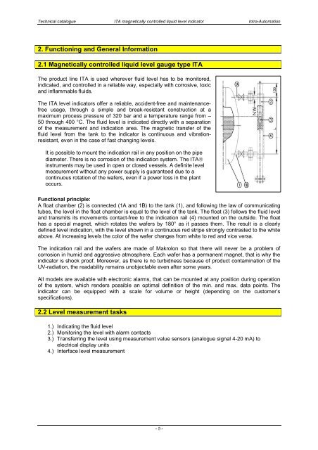
Functional principle:<br />
A float chamber (2) is connected (1A and 1B) to the tank (1), and following the law of communicating<br />
tubes, the level in the float chamber is equal to the level of the tank. The float (3) follows the fluid level<br />
and transmits its movements contact-free to the indication rail (4) mounted on the outside. The float<br />
has a special magnet, which rotates the wafers by 180° as it passes them. The result is a clearly<br />
defined level indication, with the level shown in a continuous red stripe strongly contrasted to the white<br />
above. At increasing levels the color of the wafer changes from white to red and vice versa.<br />
The indication rail and the wafers are made of Makrolon so that there will never be a problem of<br />
corrosion in humid and aggressive atmosphere. Each wafer has a permanent magnet, that is why the<br />
indicator is shock proof. Moreover, as there is no turbidness because of product contamination of the<br />
UV-radiation, the readability remains unobjectable even after some years.<br />
All models are available with electronic alarms, that can be mounted at any position during operation<br />
of the system, which renders possible an optimal definition of the min. and max. data points. The<br />
indicator can be equipped with a scale for volume or height (depending on the customer’s<br />
specifications).<br />
2.2 Level measurement tasks<br />
1.) Indicating the fluid level<br />
2.) Monitoring the level with alarm contacts<br />
3.) Transferring the level using measurement value sensors (analogue signal 4-20 mA) to<br />
electrical display units<br />
4.) Interface level measurement<br />
- 5 -