ITA Technical Catalogue
ITA Technical Catalogue
ITA Technical Catalogue

Create successful ePaper yourself
Turn your PDF publications into a flip-book with our unique Google optimized e-Paper software.
<strong>Technical</strong> catalogue <strong>ITA</strong> magnetically controlled liquid level indicator Intra-Automation<br />
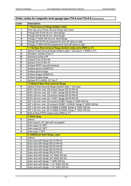
Order codes for magnetic level gauge type <strong>ITA</strong>-6 and <strong>ITA</strong>-6.0 (Continuation)<br />
Code<br />
Description<br />
7. Float removal flange (bottom side)<br />
1 End cap (only if float removal flange (top side))<br />
2 Flange DN 32 PN 40 incl. blind flange<br />
3 Flange DN 50 PN 40 incl. blind flange<br />
A Flange 2" ANSI 300 lbs incl. blind flange<br />
4 Flange DN 50 PN 40 prepared for shut off valve on side<br />
B Flange 2" ANSI 300 lbs prepared for shut off valve on side<br />
7.1 Surface float removal flange (bottom side) (only DN50 or 2")<br />
0 without (Float removal flange (bottom side) = end cap or < DN50 or 2")<br />
A Standard- Surface Form C<br />
B Standard-Surface RF<br />
C Surface Form D Rz=40<br />
D Surface Form E Rz=16<br />
E Surface RFSF (smooth finished)<br />
F Surface groove (DIN2512)<br />
G Surface groove large<br />
H Surface tongue (DIN2512)<br />
K Surface tongue-large<br />
L Surface RTJ (ANSI) 1/2" bis 2"<br />
7.2 Bolts & Nuts float removal flange<br />
0 without (Float removal flange (bottom side) = end cap)<br />
1 M16 x 65 mm; mat. CS zinced; flange DN 32 PN 40<br />
2 M16 x 65 mm; mat. SS 1.4301; flange DN 32 PN 40<br />
3 M16 x 65 mm; mat. CS zinced; flange DN 50 PN 40<br />
4 M16 x 65 mm; mat. SS 1.4301; flange DN 50 PN 40<br />
A 5/8" x 83 mm; mat. CS zinced A193B7; flange 2" ANSI 300 lbs<br />
B 5/8" x 89 mm; mat. CS zinced A193B7 / A1942H; flange 2" ANSI 300 lbs<br />
C 5/8" x 83 mm; mat. SS A193B8 A1948M, flange 2" ANSI 300 lbs<br />
D 5/8" x 89 mm; mat. SS A193B8 A1948M; flange 2" ANSI 300 lbs<br />
E Bolts & Nuts PTFE-coated (only DN50 or 2")<br />
8. Drain plug<br />
0 without<br />
1 Drain plug G 1/2" with soft iron gasket<br />
2 Drain plug 1/2" NPT<br />
3 Drain plug 3/4" NPT<br />
4 Drain plug 1" NPT<br />
9. Additional drain flange, open<br />
0 without<br />
1 Drain stud with flange DN 15 PN 40<br />
2 Drain stud with flange DN 20 PN 40<br />
3 Drain stud with flange DN 25 PN 40<br />
4 Drain stud with flange DN 32 PN 40<br />
5 Drain stud with flange DN 40 PN 40<br />
A Drain stud with flange 1/2" ANSI 300 lbs<br />
B Drain stud with flange 3/4" ANSI 300 lbs<br />
C Drain stud with flange 1" ANSI 300 lbs<br />
D Drain stud with flange 1 1/4" ANSI 300 lbs<br />
E Drain stud with flange 1 1/2" ANSI 300 lbs<br />
- 73 -