installation instructions for the model 777-690-p - SymCom
installation instructions for the model 777-690-p - SymCom
installation instructions for the model 777-690-p - SymCom

Create successful ePaper yourself
Turn your PDF publications into a flip-book with our unique Google optimized e-Paper software.
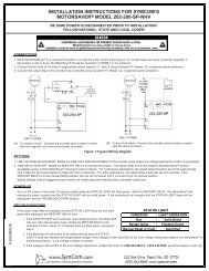
COMMUNICATIONS PORT/REMOTE RESET<br />
The unit comes with a 9-pin sub-D connector <strong>for</strong> remote communications and/or <strong>for</strong> using a remotely<br />
located reset button. If communications are desired, a communication module (part number<br />
RS485MS-2W) needs to be plugged into this 9-pin connector (this is mandatory when<br />
communicating with <strong>the</strong> unit). This module provides isolation, signal conditioning <strong>for</strong> compatibility<br />
with Modbus RTU and RS-485 networks, and provides terminals <strong>for</strong> terminating <strong>the</strong> shielded<br />
communications cable. Up to 99 units can be installed on one RS-485 network.<br />
Fur<strong>the</strong>r in<strong>for</strong>mation can be obtained at www.symcom.com or by calling in a request. A remote reset<br />
button can be hooked up to <strong>the</strong> communications module (part number RS485MS-2W) or can be<br />
hooked directly to <strong>the</strong> 9-pin connector using a male sub-D connector. It should be wired as shown in<br />
Figure 5.<br />
Figure 5: Remote Reset Button Wiring Diagram<br />
- 11 -<br />
6/07 A1