installation instructions for the model 777-690-p - SymCom
installation instructions for the model 777-690-p - SymCom
installation instructions for the model 777-690-p - SymCom

Create successful ePaper yourself
Turn your PDF publications into a flip-book with our unique Google optimized e-Paper software.
GROUND FAULT TESTING PROCEDURE<br />
A ground fault test must be per<strong>for</strong>med be<strong>for</strong>e installing <strong>the</strong> MotorSaver®Plus as required by<br />
UL1053 and NEC, ANSI/NFPA 70.<br />
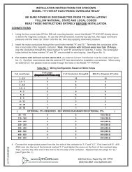
1. Disconnect power.<br />
2. Hook up <strong>the</strong> three line voltages to L1, L2, and L3 as required by <strong>the</strong> <strong>installation</strong> <strong>instructions</strong>.<br />
3. Program <strong>the</strong> desired parameters into <strong>the</strong> unit. For test purposes, set MULT to 1 and GF to <strong>the</strong><br />
minimum allowed setting.<br />
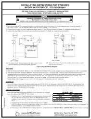
4. Construct <strong>the</strong> circuit, using an AC power supply. This circuit simulates a ground fault condition by<br />
generating a current in one of <strong>the</strong> phases. Alternate test circuits may be used. The only<br />
requirement is <strong>the</strong> current through <strong>the</strong> current trans<strong>for</strong>mer must be between 115% and 150% of<br />
<strong>the</strong> GF setting and pass through only one CT window.<br />
5. The values of V and R will be determined by <strong>the</strong> current required to generate a GF trip condition:<br />
I = Vrms/R, where I = 115% of GF setting.<br />
6. Place <strong>the</strong> unit in <strong>the</strong> RUN position, apply 3-phase power and allow <strong>the</strong> NO contact to close.<br />
7. Energize <strong>the</strong> test circuit by pushing and holding <strong>the</strong> test pushbutton until <strong>the</strong> unit trips (within 8.5<br />
seconds). The display should show “GrF” and <strong>the</strong> NO contacts should be open. Release <strong>the</strong> NO<br />
pushbutton.<br />
8. The results of <strong>the</strong> test are to be recorded on <strong>the</strong> test <strong>for</strong>m provided below. The <strong>for</strong>m should be<br />
kept by those in charge of <strong>the</strong> building’s electrical <strong>installation</strong> in order to be available to <strong>the</strong><br />
authority having jurisdiction.<br />
9. Confirm programmed parameters and proceed with <strong>installation</strong> <strong>instructions</strong>.<br />
- 13 -<br />
6/07 A1