EM3800SXâ¢EM5000SXâ¢EM6500SX - Geotech Environmental ...
EM3800SXâ¢EM5000SXâ¢EM6500SX - Geotech Environmental ...
EM3800SXâ¢EM5000SXâ¢EM6500SX - Geotech Environmental ...

You also want an ePaper? Increase the reach of your titles
YUMPU automatically turns print PDFs into web optimized ePapers that Google loves.
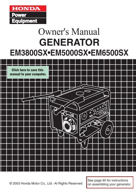
EM3800SX•EM5000SX•EM6500SX<br />
See page 60 for instructions<br />
on assembling your generator.
The engine exhaust from this product<br />
contains chemicals known to the State<br />
of California to cause cancer, birth<br />
defects or other reproductive harm.<br />
Exhaust contains poisonous carbon monoxide gas that can build up<br />
to dangerous levels in closed areas.<br />
Breathing carbon monoxide can cause unconsciousness or death.<br />
Never run the generator in a closed, or even partly closed area where<br />
people may be present.<br />
The generator is a potential source of electrical shock if misused. Do<br />
not expose the generator to moisture, rain or snow. Do not let the<br />
generator get wet, and do not operate it with wet hands.<br />
Keep this owner’s manual handy so that you can refer to it at any time.<br />
This owner’s manual is considered a permanent part of the generator<br />
and should remain with the generator if resold.<br />
The information and specifications included in this publication were in<br />
effect at the time of approval for printing. Honda Motor Co., Ltd.<br />
reserves the right, however, to discontinue or change specifications or<br />
design at any time without notice and without incurring any obligation<br />
whatever. No part of this publication may be reproduced without<br />
written permission.
Congratulations on your selection of a Honda generator. We are<br />
certain you will be pleased with your purchase of one of the finest<br />
generators on the market.<br />
We want to help you get the best results from your new generator and<br />
to operate it safely. This manual contains the information on how to<br />
do that; please read it carefully.<br />
As you read this manual, you will find information preceded by a<br />
symbol. That information is intended to help you avoid<br />
damage to your generator, other property, or the environment.<br />
We suggest you read the warranty policy to fully understand its<br />
coverage and your responsibilities of ownership. The warranty policy<br />
is a separate document that should have been given to you by your<br />
dealer.<br />
When your generator needs scheduled maintenance, keep in mind<br />
that your Honda servicing dealer is specially trained in servicing<br />
Honda generators. Your authorized Honda servicing dealer is<br />
dedicated to your satisfaction and will be pleased to answer your<br />
questions and concerns.<br />
Best Wishes,<br />
Honda Motor Co., Ltd.<br />
1
A FEW WORDS ABOUT SAFETY<br />
Your safety and the safety of others are very important. And using<br />
this generator safely is an important responsibility.<br />
To help you make informed decisions about safety, we have provided<br />
operating procedures and other information on labels and in this<br />
manual. This information alerts you to potential hazards that could<br />
hurt you or others.<br />
Of course, it is not practical or possible to warn you about all the<br />
hazards associated with operating or maintaining a generator. You<br />
must use your own good judgement.<br />
You will find important safety information in a variety of forms,<br />
including:<br />
Safety Labels on the generator.<br />
Safety Messages preceded by a safety alert symbol<br />
of three signal words, DANGER, WARNING, or CAUTION.<br />
These signal words mean:<br />
You WILL be KILLED or SERIOUSLY HURT if<br />
you don’t follow instructions.<br />
You CAN be KILLED or SERIOUSLY HURT if<br />
you don’t follow instructions.<br />
You CAN be HURT if you don’t follow<br />
instructions.<br />
Safety Headings such as IMPORTANT SAFETY INFORMATION.<br />
Safety Section such as GENERATOR SAFETY.<br />
Instructions how to use this generator correctly and safely.<br />
and one<br />
This entire book is filled with important safety information please<br />
read it carefully.<br />
2
CONTENTS<br />
GENERATOR SAFETY ............................................................................... 5<br />
Safety Label Locations ........................................................................ 5<br />
Important Safety Information ............................................................. 6<br />
COMPONENT IDENTIFICATION ............................................................... 8<br />
CONTROLS ............................................................................................... 10<br />
Engine Switch ..................................................................................... 10<br />
Starter Grip ......................................................................................... 10<br />
Fuel Valve Lever ................................................................................. 11<br />
Choke Rod ........................................................................................... 11<br />
Voltage Selector Switch (Dual Voltage System) ............................. 12<br />
Ground Terminal ................................................................................ 12<br />
DC Terminals ...................................................................................... 13<br />
DC Circuit Protector ........................................................................... 13<br />
Oil Alert System ............................................................................... 14<br />
Auto Throttle System ....................................................................... 14<br />
AC Circuit Breaker .............................................................................. 15<br />
AC Circuit Protector ........................................................................... 16<br />
GENERATOR USE .................................................................................... 17<br />
Connections to a Building’s Electrical System ................................ 17<br />
Ground System ...................................................................................17<br />
Special Requirements ........................................................................ 17<br />
AC Applications .................................................................................. 18<br />
AC Operation ...................................................................................... 19<br />
AC Receptacle Selection .................................................................... 20<br />
DC Operation ...................................................................................... 26<br />
Auto Throttle System ....................................................................... 28<br />
High Altitude Operation ..................................................................... 29<br />
PRE-OPERATION CHECK ........................................................................ 30<br />
Engine Oil ........................................................................................... 30<br />
Refueling ............................................................................................. 31<br />
Fuel Recommendations ..................................................................... 32<br />
STARTING THE ENGINE/STOPPING THE ENGINE ............................... 33<br />
3
MAINTENANCE ....................................................................................... 35<br />
The Importance of Maintenance ....................................................... 35<br />
Maintenance Safety ........................................................................... 36<br />
Maintenance Schedule ...................................................................... 37<br />
Engine Oil Change ............................................................................. 38<br />
Air Cleaner Service ............................................................................ 39<br />
Fuel Sediment Cup Cleaning ............................................................ 40<br />
Spark Plug Service ............................................................................. 41<br />
Spark Arrester Maintenance ............................................................. 42<br />
Fuse Replacement .............................................................................. 43<br />
STORAGE ................................................................................................. 44<br />
Storage Preparation ........................................................................... 44<br />
Cleaning ............................................................................................ 44<br />
Fuel .................................................................................................... 44<br />
Engine Oil .......................................................................................... 46<br />
Storage Precautions .......................................................................... 48<br />
Removal From Storage ..................................................................... 48<br />
TRANSPORTING ...................................................................................... 49<br />
TROUBLESHOOTING .............................................................................. 50<br />
TECHNICAL INFORMATION ................................................................... 52<br />
Emission Control System Information ............................................. 52<br />
Air Index .............................................................................................. 54<br />
WIRING DIAGRAM .................................................................................. 55<br />
SPECIFICATIONS ..................................................................................... 57<br />
ASSEMBLY ............................................................................................... 60<br />
WARRANTY SERVICE INFORMATION .................................................. 72<br />
DEALER LOCATOR INFORMATION .................................................. 72<br />
CUSTOMER SERVICE INFORMATION ............................................. 72<br />
Honda PUBLICATIONS ...................................................................... 73<br />
INDEX ....................................................................................................... 74<br />
4
GENERATOR SAFETY<br />
SAFETY LABEL LOCATIONS<br />
These labels warn you of potential hazards that can cause serious<br />
injury. Read them carefully.<br />
If a label comes off or becomes hard to read, contact your Honda<br />
generator dealer for a replacement.<br />
Non-California type<br />
California type<br />
5
IMPORTANT SAFETY INFORMATION<br />
Honda generators are designed to give safe and dependable service if<br />
operated according to instructions. Read and understand this owner’s<br />
manual before operating your generator. You can help prevent<br />
accidents by being familiar with your generator’s controls and by<br />
observing safe operating procedures.<br />
Operator Responsibility<br />
Know how to stop the generator quickly in case of emergency.<br />
Understand the use of all generator controls, output receptacles,<br />
and connections.<br />
Be sure that anyone who operates the generator receives proper<br />
instruction. Do not let children operate the generator without<br />
parental supervision.<br />
Carbon Monoxide Hazards<br />
Exhaust contains poisonous carbon monoxide, a colorless and<br />
odorless gas. Breathing carbon monoxide can cause loss of<br />
consciousness and may lead to death.<br />
If you run the generator in a confined or even partly enclosed area,<br />
the air you breathe could contain dangerous amount of exhaust gas.<br />
Never run your generator inside a garage, house, or near open<br />
windows or doors.<br />
6
Electric Shock Hazards<br />
The generator produces enough electric power to cause a serious<br />
shock or electrocution if misused.<br />
Using a generator or electrical appliance in wet conditions, such as<br />
rain or snow, or near a pool or sprinkler system, or when your hands<br />
are wet, could result in electrocution. Keep the generator dry.<br />
If the generator is stored outdoors, unprotected from the weather,<br />
check all of the electrical components on the control panel before<br />
each use. Moisture or ice can cause a malfunction or short circuit in<br />
electrical components that could result in electrocution.<br />
Do not connect to a building’s electrical system unless an isolation<br />
switch has been installed by a qualified electrician.<br />
Fire and Burn Hazards<br />
The exhaust system gets hot enough to ignite some materials.<br />
Keep the generator at least 3 feet (1 meter) away from buildings<br />
and other equipment during operation.<br />
Do not enclose the generator in any structure.<br />
Keep flammable materials away from the generator.<br />
The muffler becomes very hot during operation and remains hot for<br />
a while after stopping the engine. Be careful not to touch the muffler<br />
while it is hot. Let the engine cool before storing the generator<br />
indoors.<br />
Gasoline is extremely flammable and is explosive under certain<br />
conditions. Do not smoke or allow flames or sparks where the<br />
generator is refueled or where gasoline is stored. Refuel in a wellventilated<br />
area with the engine stopped.<br />
Fuel vapors are extremely flammable and may ignite after the<br />
engine has started. Make sure that any spilled fuel has been wiped<br />
up before starting the generator.<br />
7
COMPONENT IDENTIFICATION<br />
CHOKE ROD<br />
ENGINE SWITCH<br />
CONTROL PANEL<br />
AIR CLEANER<br />
FUEL VALVE LEVER<br />
STARTER GRIP<br />
CONTROL PANEL<br />
<br />
1:Except EM3800SX<br />
ENGINE SERIAL NUMBER<br />
AC CIRCUIT BREAKER<br />
AC CIRCUIT PROTECTORS<br />
FUSE<br />
OIL DRAIN PLUG<br />
OIL FILLER CAP/DIPSTICK<br />
120 ONLY120/240<br />
VOLTAGE SELECTOR SWITCH<br />
120/240V AC<br />
RECEPTACLE<br />
DC CIRCUIT<br />
PROTECTOR<br />
<br />
1<br />
DC OUTPUT<br />
TERMINAL<br />
8<br />
AUTO THROTTLE<br />
SWITCH<br />
120V AC RECEPTACLES<br />
GROUND TERMINAL
TRANSPORT HANDLE<br />
FUEL TANK CAP<br />
FUEL GAUGE<br />
SPARK PLUG CAP<br />
FRAME SERIAL NUMBER<br />
STAND<br />
WHEEL<br />
MUFFLER<br />
* Record the engine and frame serial numbers and date of purchase<br />
for your future reference. Refer to these serial numbers when<br />
ordering parts and when making technical or warranty inquiries (see<br />
page 72 ).<br />
Engine serial number:<br />
Frame serial number:<br />
Date of purchase:<br />
9
CONTROLS<br />
Engine Switch<br />
To start and stop the engine.<br />
Key position:<br />
OFF: To stop the engine. Key can be removed/inserted.<br />
ON: To run the engine after starting.<br />
START: To start the engine by operating the starter motor.<br />
OFF<br />
ON<br />
START<br />
ENGINE SWITCH<br />
Starter Grip<br />
To start the engine, pull the starter grip lightly until resistance is felt,<br />
and then pull briskly.<br />
Do not allow the starter grip to snap back against the engine. Return it<br />
gently to prevent damage to the starter.<br />
The recoil starter is used to start the engine if the generator is not<br />
equipped with a 12-volt battery to operate the starter motor, or if the<br />
battery does not contain adequate charge to operate the starter motor.<br />
RECOIL STARTER<br />
STARTER GRIP<br />
10
Fuel Valve Lever<br />
The fuel valve is located between the fuel tank and carburetor. When<br />
the valve lever is in the ON position, fuel is allowed to flow from the<br />
fuel tank to the carburetor. Be sure to return the fuel valve lever to the<br />
OFF position after stopping the engine.<br />
FUEL VALVE LEVER<br />
OFF<br />
ON<br />
Choke Rod<br />
The choke is used to provide an enriched fuel mixture when starting a<br />
cold engine. It can be opened and closed by operating the choke rod<br />
manually. Pull the rod out toward CLOSED to enrich the mixture for<br />
cold starting.<br />
OPEN<br />
CLOSED<br />
CHOKE ROD<br />
11
Voltage Selector Switch (Dual Voltage System)<br />
The voltage selector switch switches the main power carrying<br />
windings of the generator to produce ‘‘120V ONLY’’ or ‘‘120/240V’’. If a<br />
240V appliance is connected to the 4-prong receptacle, the switch<br />
must be in the ‘‘120/240V’’ position. If only a 120V appliance is being<br />
connected to any of the 120V 3-prong receptacles, select the ‘‘120V<br />
ONLY’’ position.<br />
Switch Position<br />
120/240V: The 120V and 120/240V receptacles can be used<br />
simultaneously.<br />
120V ONLY: ONLY the 120V receptacles can be used. Do not use the<br />
120/240V receptacle in this position. The most power<br />
will be available at the 30A 120V locking plug<br />
receptacle.<br />
VOLTAGE SELECTOR SWITCH<br />
120/240V<br />
120V ONLY<br />
120/240V<br />
120V ONLY<br />
GROUND TERMINAL<br />
Ground Terminal<br />
The generator ground terminal is connected to the frame of the<br />
generator, the metal non-current-carrying parts of the generator, and<br />
the ground terminals of each receptacle.<br />
Before using the ground terminal, consult a qualified electrician,<br />
electrical inspector, or local agency having jurisdiction for local codes<br />
or ordinances that apply to the intended use of the generator.<br />
12
DC Terminals<br />
The DC terminals may ONLY be used for charging 12-volt automotive<br />
type batteries.<br />
The terminals are colored red to identify the positive ( ) terminal and<br />
black to identify the negative ( ) terminal. The battery must be<br />
connected to the generator DC terminals with the proper polarity<br />
(battery positive to generator red terminal and battery negative to the<br />
generator black terminal).<br />
DC Circuit Protector<br />
The DC circuit protector automatically shuts off the DC battery<br />
charging circuit when the DC charging circuit is overloaded, when<br />
there is a problem with the battery, or when the connections between<br />
the battery and the generator are improper.<br />
DC CIRCUIT<br />
PROTECTOR<br />
NEGATIVE TERMINAL<br />
(BLACK)<br />
POSITIVE TERMINAL<br />
(RED)<br />
13
Oil Alert System<br />
The Oil Alert system is designed to prevent engine damage caused<br />
by an insufficient amount of oil in the crankcase. Before the oil level in<br />
the crankcase can fall below a safe limit, the Oil Alert system will<br />
automatically stop the engine (the engine switch will remain in the ON<br />
position). The Oil Alert system should not take the place of checking<br />
the oil level before each use.<br />
If the engine stops and will not restart, check the engine oil level (see<br />
page 30)<br />
before troubleshooting in other areas.<br />
Auto Throttle System<br />
The Auto Throttle system automatically reduces engine speed when<br />
all loads are turned off or disconnected. When appliances are turned<br />
on or reconnected, the engine returns to the rated speed.<br />
Switch Position<br />
AUTO: Recommended to minimize fuel consumption and further<br />
reduce noise levels when no load is applied to the generator.<br />
OFF: The Auto Throttle system does not operate.<br />
Recommended to minimize warm-up time when the<br />
generator is started and when starting a load with large startup<br />
power equipments.<br />
AUTO THROTTLE SWITCH<br />
OFF<br />
OFF<br />
ON<br />
ON<br />
14
AC Circuit Breaker<br />
The AC circuit breaker will automatically switch OFF if there is a short<br />
circuit or a significant overload of the generator at the receptacle. If the<br />
AC circuit breaker is switched OFF automatically, check that the<br />
appliance is working properly and does not exceed the rated load<br />
capacity of the circuit before switching the AC circuit breaker ON again.<br />
The AC circuit breaker may be used to switch the generator power ON<br />
or OFF.<br />
ON<br />
OFF<br />
AC CIRCUIT BREAKER<br />
15
AC Circuit Protector<br />
The AC circuit protectors will automatically switch OFF if there is a<br />
short circuit or a significant overload of the generator at the 20A 120V,<br />
30A 120V locking plug, or 120/240V locking plug receptacle. If an AC<br />
circuit protector switches OFF automatically, check that the appliance<br />
is working properly and does not exceed the rated load capacity of the<br />
circuit before resetting the AC circuit protector ON.<br />
AC CIRCUIT PROTECTORS<br />
ON<br />
<br />
1<br />
OFF<br />
<br />
1:Except EM3800SX<br />
16
GENERATOR USE<br />
Connections to a Building’s Electrical System<br />
Connections for standby power to a building’s electrical system must<br />
be made by a qualified electrician. The connection must isolate the<br />
generator power from utility power, and must comply with all<br />
applicable laws and electrical codes. A transfer switch, which isolates<br />
generator power from utility power, is available through authorized<br />
Honda generator dealers.<br />
Improper connections to a building’s electrical system can allow<br />
electrical current from the generator to backfeed into the utility lines.<br />
Such backfeed may electrocute utility company workers or others<br />
who contact the lines during a power outage, and the generator may<br />
explode, burn, or cause fires when utility power is restored. Consult<br />
the utility company or a qualified electrician.<br />
Ground System<br />
Honda portable generators have a system ground that connects<br />
generator frame components to the ground terminals in the AC output<br />
receptacles. The system ground is not connected to the AC neutral<br />
wire. If the generator is tested by a receptacle tester, it will show the<br />
same ground circuit condition as for a home receptacle.<br />
Special Requirements<br />
There may be Federal or State Occupational Safety and Health<br />
Administration (OSHA) regulations, local codes, or ordinances that<br />
apply to the intended use of the generator. Please consult a qualified<br />
electrician, electrical inspector, or the local agency having jurisdiction.<br />
In some areas, generators are required to be registered with local<br />
utility companies.<br />
17
AC Applications<br />
Before connecting an appliance or power cord to the generator:<br />
Make sure that it is in good working order. Faulty appliances or<br />
power cords can create a potential for electrical shock.<br />
If an appliance begins to operate abnormally, becomes sluggish, or<br />
stops suddenly, turn it off immediately. Disconnect the appliance,<br />
and determine whether the problem is the appliance or the rated<br />
load capacity of the generator has been exceeded.<br />
Make sure that the electrical rating of the tool or appliance does not<br />
exceed that of the generator. Never exceed the maximum power<br />
rating of the generator. Power levels between rated and maximum<br />
may be used for no more than 30 minutes.<br />
Substantial overloading will open the circuit breaker. Exceeding the<br />
time limit for maximum power operation or slightly overloading the<br />
generator may not switch the circuit breaker or circuit protector OFF,<br />
but will shorten the service life of the generator.<br />
Limit operation requiring maximum power to 30 minutes.<br />
Maximum power is:<br />
EM3800SX: 3.8 kVA<br />
EM5000SX: 5.0 kVA<br />
EM6500SX: 6.5 kVA<br />
For continuous operation (longer than 30 minutes), do not exceed the<br />
rated power.<br />
Rated power is:<br />
EM3800SX:<br />
EM5000SX:<br />
3.3 kVA<br />
4.5 kVA<br />
EM6500SX: 5.5 kVA<br />
The total power requirements (VA) of all appliances connected must<br />
be considered. Appliance and power tool manufacturers usually list<br />
rating information near the model number or serial number.<br />
18
AC Operation<br />
1. Start the engine (see page 33 ).<br />
2. Turn the voltage selector switch to either position.<br />
With the voltage selector switch in the ‘‘120/240V’’ position, you can<br />
use the 120V and 120/240V receptacles simultaneously. If you are<br />
NOT using the 120/240V receptacle, then select the ‘‘120V ONLY’’<br />
position.<br />
3. Switch the AC circuit breaker ON.<br />
4. Plug in the appliance.<br />
Be sure that all appliances are in good working order before<br />
connecting them to the generator. If an appliance begins to operate<br />
abnormally, becomes sluggish, or stops suddenly, turn off the ignition<br />
switch lever immediately. Then disconnect the appliance and examine<br />
it for signs of malfunction.<br />
Most motorized appliances require more than their rated power for<br />
startup.<br />
Do not exceed the current limit specified for any one receptacle. If an<br />
overloaded circuit causes the AC circuit breaker or AC circuit protector<br />
to switch OFF, reduce the electrical load on the circuit, wait a few<br />
minutes and then reset the AC circuit breaker or AC circuit protector.<br />
VOLTAGE SELECTOR SWITCH<br />
AC CIRCUIT PROTECTORS<br />
<br />
1<br />
AC CIRCUIT BREAKER<br />
1:Except EM3800SX<br />
<br />
19
AC Receptacle Selection<br />
The control panel, shown below, has a voltage selector switch and<br />
four receptacles. Receptacle 4, the 240-volt receptacle, has two<br />
powered terminals, 4A and 4B.<br />
EM3800SX:<br />
4B<br />
4A<br />
120V 30A<br />
120V 20A (in total)<br />
120V 20A (in total)<br />
4A<br />
& 4B<br />
120/240V 20A<br />
Power Producing Circuits<br />
This generator is equipped with two power generating circuits. When<br />
the voltage selector switch is in the 120V/240V position, each of the<br />
two power producing circuits supplies power to specific receptacles.<br />
When the voltage selector switch is in the 120V ONLY position, the<br />
power producing circuits operate in parallel, sharing the total load<br />
connected to terminal 4A and receptacles 1, 2, and 3.<br />
120V/240V<br />
120V ONLY<br />
POWER<br />
CIRCUIT 1<br />
POWER<br />
CIRCUIT 2<br />
POWER CIRCUIT 1<br />
POWER CIRCUIT 2<br />
20
Voltage Selector Switch<br />
The power available to each receptacle depends on the position of the<br />
voltage selector switch.<br />
Switch Position<br />
120V ONLY<br />
120V/240V<br />
Receptacle<br />
1<br />
2<br />
3<br />
4A<br />
4B<br />
1<br />
2<br />
3<br />
4A-4B<br />
Available Power<br />
27.5A at 120V<br />
20A at 120V<br />
20A at 120V<br />
20A at 120V<br />
None<br />
13.8A at 120V<br />
13.8A at 120V<br />
13.8A at 120V<br />
13.8A at 240V<br />
120V ONLY Position<br />
When the voltage selector switch is in the 120V ONLY position, you<br />
do not need to spread the load over the receptacles. You must,<br />
however, make sure the load on any receptacle does not exceed its<br />
available power shown in the preceding table and the total load does<br />
not exceed 27.5 amps.<br />
120V/240V Position<br />
When the voltage selector switch is in the 120V/240V position, you<br />
must balance the load. Divide the load between the two sets of<br />
receptacles shown below. Balancing is necessary because each set of<br />
receptacles is powered by only one power producing circuit that can<br />
produce a maximum of 13.8 amps.<br />
Set of<br />
Receptacles<br />
134B<br />
2<br />
4A<br />
Total Current<br />
Available<br />
13.8A<br />
13.8A<br />
Power Producing<br />
Circuit<br />
1<br />
2<br />
21
The control panel, shown below, has a voltage selector switch and<br />
four receptacles. Receptacle 4, the 240-volt receptacle, has two<br />
powered terminals, 4A and 4B.<br />
EM5000SX:<br />
4B<br />
4A<br />
120V 30A<br />
120V 20A (in total)<br />
120V 20A (in total)<br />
4A<br />
& 4B<br />
120/240V 30A<br />
Power Producing Circuits<br />
This generator is equipped with two power generating circuits. When<br />
the voltage selector switch is in the 120V/240V position, each of the<br />
two power producing circuits supplies power to specific receptacles.<br />
When the voltage selector switch is in the 120V ONLY position, the<br />
power producing circuits operate in parallel, sharing the total load<br />
connected to terminal 4A and receptacles 1, 2, and 3.<br />
120V/240V<br />
120V ONLY<br />
POWER<br />
CIRCUIT 1<br />
POWER<br />
CIRCUIT 2<br />
POWER CIRCUIT 1<br />
POWER CIRCUIT 2<br />
22
Voltage Selector Switch<br />
The power available to each receptacle depends on the position of the<br />
voltage selector switch.<br />
Switch Position<br />
120V ONLY<br />
120V/240V<br />
Receptacle<br />
1<br />
2<br />
3<br />
4A<br />
4B<br />
1<br />
2<br />
3<br />
4A-4B<br />
Available Power<br />
30A at 120V<br />
20A at 120V<br />
20A at 120V<br />
30A at 120V<br />
None<br />
18.8A at 120V<br />
18.8A at 120V<br />
18.8A at 120V<br />
18.8A at 240V<br />
120V ONLY Position<br />
When the voltage selector switch is in the 120V ONLY position, you<br />
do not need to spread the load over the receptacles. You must,<br />
however, make sure the load on any receptacle does not exceed its<br />
available power shown in the preceding table and the total load does<br />
not exceed 37.5 amps.<br />
120V/240V Position<br />
When the voltage selector switch is in the 120V/240V position, you<br />
must balance the load. Divide the load between the two sets of<br />
receptacles shown below. Balancing is necessary because each set of<br />
receptacles is powered by only one power producing circuit that can<br />
produce a maximum of 18.8 amps.<br />
Set of<br />
Receptacles<br />
134B<br />
2<br />
4A<br />
Total Current<br />
Available<br />
18.8A<br />
18.8A<br />
Power Producing<br />
Circuit<br />
1<br />
2<br />
23
The control panel, shown below, has a voltage selector switch and<br />
four receptacles. Receptacle 4, the 240-volt receptacle, has two<br />
powered terminals, 4A and 4B.<br />
EM6500SX:<br />
4B<br />
4A<br />
120V 30A<br />
120V 20A (in total)<br />
120V 20A (in total)<br />
4A<br />
& 4B<br />
120/240V 30A<br />
Power Producing Circuits<br />
This generator is equipped with two power generating circuits. When<br />
the voltage selector switch is in the 120V/240V position, each of the<br />
two power producing circuits supplies power to specific receptacles.<br />
When the voltage selector switch is in the 120V ONLY position, the<br />
power producing circuits operate in parallel, sharing the total load<br />
connected to terminal 4A and receptacles 1, 2, and 3.<br />
120V/240V<br />
120V ONLY<br />
POWER<br />
CIRCUIT 1<br />
POWER<br />
CIRCUIT 2<br />
POWER CIRCUIT 1<br />
POWER CIRCUIT 2<br />
24
Voltage Selector Switch<br />
The power available to each receptacle depends on the position of the<br />
voltage selector switch.<br />
Switch Position<br />
120V ONLY<br />
120V/240V<br />
Receptacle<br />
1<br />
2<br />
3<br />
4A<br />
4B<br />
1<br />
2<br />
3<br />
4A-4B<br />
Available Power<br />
30A at 120V<br />
20A at 120V<br />
20A at 120V<br />
30A at 120V<br />
None<br />
22.9A at 120V<br />
20A at 120V<br />
20A at 120V<br />
22.9A at 240V<br />
120V ONLY Position<br />
When the voltage selector switch is in the 120V ONLY position, you<br />
do not need to spread the load over the receptacles. You must,<br />
however, make sure the load on any receptacle does not exceed its<br />
available power shown in the preceding table and the total load does<br />
not exceed 45.8 amps.<br />
120V/240V Position<br />
When the voltage selector switch is in the 120V/240V position, you<br />
must balance the load. Divide the load between the two sets of<br />
receptacles shown below. Balancing is necessary because each set of<br />
receptacles is powered by only one power producing circuit that can<br />
produce a maximum of 22.9 amps.<br />
Set of<br />
Receptacles<br />
134B<br />
2<br />
4A<br />
Total Current<br />
Available<br />
22.9A<br />
22.9A<br />
Power Producing<br />
Circuit<br />
1<br />
2<br />
25
DC Operation<br />
The DC terminals may ONLY be used for charging 12-volt automotive<br />
type batteries.<br />
Connecting the battery charging cables:<br />
1. Before connecting the battery charging cables to a battery that is<br />
installed in a vehicle, disconnect the vehicle ground battery cable<br />
from the battery negative ( ) terminal.<br />
The battery gives off explosive gases; keep sparks, flames, and<br />
cigarettes away. Provide adequate ventilation when charging or<br />
using batteries.<br />
WARNING: Battery posts, terminals, and related accessories contain<br />
lead and lead components. Wash hands after handling.<br />
2. Connect the positive ( ) battery cable to the battery positive ( )<br />
terminal.<br />
3. Connect the other end of the positive ( ) battery cable to the<br />
generator positive ( ) terminal.<br />
DC CIRCUIT<br />
PROTECTOR<br />
NEGATIVE TERMINAL<br />
(BLACK)<br />
POSITIVE TERMINAL<br />
(RED)<br />
4. Connect the negative ( ) battery cable to the battery negative ( )<br />
terminal.<br />
5. Connect the other end of the negative ( ) battery cable to the<br />
generator negative ( ) terminal.<br />
6. Start the generator.<br />
Do not start the vehicle while the battery charging cable is connected<br />
and the generator is running. The vehicle or the generator may be<br />
damaged.<br />
26
An overloaded DC circuit, excessive current draw by the battery, or a<br />
wiring problem will trip the DC circuit protector (PUSH button extends<br />
out). If this happens, wait a few minutes before pushing in the circuit<br />
protector to resume operation. If the DC circuit protector continues to<br />
go OFF, discontinue charging and see your authorized Honda<br />
generator dealer.<br />
Disconnecting the battery cables:<br />
1. Stop the engine.<br />
2. Disconnect the negative ( ) battery cable from the generator<br />
negative ( ) terminal.<br />
3. Disconnect the other end of the negative ( ) battery cable from the<br />
battery negative ( ) terminal.<br />
4. Disconnect the positive ( ) battery cable from the generator<br />
positive ( ) terminal.<br />
5. Disconnect the other end of the positive ( ) battery cable from the<br />
battery positive ( ) terminal.<br />
6. Reconnect the vehicle ground battery cable to the battery negative<br />
( )terminal.<br />
DC CIRCUIT<br />
PROTECTOR<br />
NEGATIVE TERMINAL<br />
(BLACK)<br />
POSITIVE TERMINAL<br />
(RED)<br />
27
Auto Throttle System<br />
With the switch in the AUTO position, engine speed is automatically<br />
reduced when ALL loads are turned OFF or disconnected. When<br />
appliances are turned ON or reconnected, the engine returns to rated<br />
speed. In the OFF position, the Auto Throttle system does not operate.<br />
The Auto Throttle system will not respond to electrical loads of less<br />
than 1 ampere or intermittent loads such as a staple gun. Turn the<br />
Auto Throttle switch to the OFF position to operate loads of less than 1<br />
amp.<br />
Appliances with large start-up power demands may not allow the<br />
engine to reach normal operating rpm when they are connected to the<br />
generator. Push the Auto Throttle switch to the OFF position and<br />
connect the appliance to the generator. If the engine still will not reach<br />
normal operating speed, check that the appliance does not exceed the<br />
rated load capacity of the generator.<br />
To avoid extended warm-up periods, keep the switch OFF until the<br />
engine reaches operating temperature.<br />
The Auto Throttle system is not effective for use with appliances that<br />
require only momentary power. If the tool or appliance will be turned<br />
ON and OFF quickly, the Auto Throttle switch should be in the OFF<br />
position.<br />
AUTO THROTTLE SWITCH<br />
OFF<br />
OFF<br />
ON<br />
ON<br />
28
High Altitude Operation<br />
At high altitude, the standard carburetor air/fuel mixture will be too<br />
rich. Performance will decrease, and fuel consumption will increase. A<br />
very rich mixture will also foul the spark plug and cause hard starting.<br />
Operation at an altitude that differs from that at which this engine was<br />
certified, for extended periods of time, may increase emissions.<br />
High altitude performance can be improved by specific modifications<br />
to the carburetor. If you always operate your generator at altitudes<br />
above 5,000 feet (1,500 meters), have your dealer perform this<br />
carburetor modification. This engine, when operated at high altitude<br />
with the carburetor modifications for high altitude use, will meet each<br />
emission standard throughout its useful life.<br />
Even with carburetor modification, engine horsepower will decrease<br />
about 3.5% for each 1,000-foot (300-meter) increase in altitude. The effect<br />
of altitude on horsepower will be greater than this if no carburetor<br />
modification is made.<br />
When the carburetor has been modified for high altitude operation,<br />
the air/fuel mixture will be too lean for low altitude use. Operation at<br />
altitudes below 5,000 feet (1,500 meters) with a modified carburetor<br />
may cause the engine to overheat and result in serious engine damage.<br />
For use at low altitudes, have your servicing dealer return the<br />
carburetor to original factory specifications.<br />
29
PRE-OPERATION CHECK<br />
Engine Oil<br />
Check the oil level BEFORE<br />
EACH USE with the generator on<br />
a level surface and the engine<br />
stopped.<br />
Use 4-stroke motor oil that<br />
meets or exceeds the<br />
requirements for API service<br />
category SJ or later (or<br />
equivalent). Always check the<br />
API SERVICE label on the oil<br />
container to be sure it includes<br />
the letters SJ or later (or<br />
equivalent).<br />
AMBIENT TEMPERATURE<br />
SAE 10W-30 is recommended for general, all-temperature use. Other<br />
viscosities shown in the chart may be used when the average<br />
temperature in your area is within the indicated range.<br />
1. Remove the oil filler cap/dipstick and wipe the dipstick clean.<br />
2. Check the oil level by inserting the dipstick into the filler neck<br />
without screwing it in.<br />
3. If the level is low, fill to the upper limit of the oil filler neck with the<br />
recommended oil.<br />
OIL FILLER HOLE<br />
OIL FILLER CAP/DIPSTICK<br />
UPPER LEVEL<br />
30
Refueling<br />
With the engine stopped, check the fuel level gauge. Refill the fuel tank<br />
if the fuel level is low.<br />
Gasoline is highly flammable and explosive.<br />
You can be burned or seriously injured when handling fuel.<br />
Stop engine and keep heat, sparks, and flame away.<br />
Refuel only outdoors.<br />
Wipe up spills immediately.<br />
Refuel in a well-ventilated area with the engine stopped. If the engine<br />
has been running, allow it to cool first. Refuel carefully to avoid<br />
spilling fuel. Do not fill above the upper limit mark.<br />
Never refuel the engine inside a building where gasoline fumes may<br />
reach flames or sparks. Keep gasoline away from appliance pilot lights,<br />
barbecues, electric appliances, power tools, etc.<br />
Spilled fuel is not only a fire hazard, it causes environmental damage.<br />
Wipe up spills immediately.<br />
FUEL GAUGE<br />
FUEL TANK CAP<br />
UPPER LIMIT MARK<br />
UPPER LIMIT MARK<br />
TETHER<br />
NON-CALIFORNIA TYPE<br />
CALIFORNIA TYPE<br />
31
Fuel can damage paint and plastic. Be careful not to spill fuel when<br />
filling your fuel tank. Damage caused by spilled fuel is not covered<br />
under warranty.<br />
After refueling, reinstall the fuel tank cap securely.<br />
Fuel Recommendations<br />
This engine is certified to operate on regular unleaded gasoline with a<br />
pump octane rating of 86 or higher.<br />
Never use stale or contaminated gasoline or an oil/gasoline mixture.<br />
Avoid getting dirt or water in the fuel tank.<br />
You may use regular unleaded gasoline containing no more than 10%<br />
ethanol (E10) or 5% methanol by volume. In addition, methanol must<br />
contain cosolvents and corrosion inhibitors.<br />
Use of fuels with content of ethanol or methanol greater than shown<br />
above may cause starting and/or performance problems. It may also<br />
damage metal, rubber, and plastic parts of the fuel system.<br />
Engine damage or performance problems that result from using a fuel<br />
with percentages of ethanol or methanol greater than shown above<br />
are not covered under warranty.<br />
32
STARTING THE ENGINE/STOPPING THE ENGINE<br />
Starting the Engine<br />
For your safety, do not operate the generator in an enclosed area such<br />
as a garage. Your generator’s exhaust contains poisonous carbon<br />
monoxide gas that can collect rapidly in an enclosed area and cause<br />
illness or death.<br />
Exhaust contains poisonous carbon monoxide gas that can build up<br />
to dangerous levels in closed areas.<br />
Breathing carbon monoxide can cause unconsciousness or death.<br />
Never run the generator in a closed, or even partly closed area where<br />
people may be present.<br />
To prevent a possible fire, keep the generator at least 3 feet (1 meter)<br />
away from building walls and other equipment during operation. Do<br />
not place flammable objects close to the engine.<br />
Operating this generator less than 3 feet (1 meter) from a building or<br />
other obstruction can cause overheating and damage the generator.<br />
For proper cooling, allow at least 3 feet (1 meter) of empty space<br />
above and around the generator.<br />
Refer to the AC OPERATION (see page 19 ) or DC OPERATION (see<br />
page 26 ) for connecting loads to the generator.<br />
1. Perform the PRE-OPERATION CHECK (see page 30 ).<br />
2. Make sure that the AC circuit breaker is in the OFF position. The<br />
generator may be hard to start if a load is connected.<br />
3. Turn the fuel valve lever to the ON position.<br />
4. The automatic choke will be closed if the engine is cold. If you want<br />
to operate the choke manually, pull the choke rod out to the CLOSED<br />
position.<br />
5. Make sure the Auto Throttle switch is in the OFF position, or more<br />
time will be required for warm up.<br />
6. Turn the engine switch to the ON position.<br />
7. Pull the starter grip lightly until resistance is felt, then pull briskly.<br />
Do not allow the starter grip to snap back against the engine. Return it<br />
gently to prevent damage to the starter.<br />
33
With electric starter:<br />
1. Connect the battery cables to the generator. (page 68 )<br />
2. Turn the engine switch to the START position and hold it there for<br />
5 seconds or until the engine starts.<br />
Operating the starter motor for more than 5 seconds can damage<br />
the motor. If the engine fails to start, release the switch and wait<br />
10 seconds before operating the starter again.<br />
If the speed of the starter motor drops after a period of time, it is an<br />
indication that the battery should be recharged.<br />
When the engine starts, allow the engine switch to return to the ON<br />
position.<br />
8. If you have manually closed the choke, push it to the OPEN position<br />
as the engine warms up.<br />
9. If you wish to use the Auto Throttle system, turn the Auto Throttle<br />
switch to the AUTO position after the engine has warmed up for 2 or<br />
3 minutes.<br />
Stopping the Engine<br />
In an emergency:<br />
To stop the engine in an emergency, move the engine switch to the<br />
OFF position.<br />
In normal use:<br />
1. Turn the AC circuit breaker to the OFF position.<br />
Disconnect DC battery charging cables.<br />
2. Turn the engine switch to the OFF position.<br />
3. Turn the fuel valve lever to the OFF position.<br />
34
MAINTENANCE<br />
The Importance of Maintenance<br />
Good maintenance is essential for safe, economical, and trouble free<br />
operation. It will also help reduce air pollution.<br />
Improper maintenance, or failure to correct a problem before<br />
operation, can cause a malfunction in which you can be seriously hurt<br />
or killed.<br />
Always follow the inspection and maintenance recommendations and<br />
schedules in this owner’s manual.<br />
To help you properly care for your generator, the following pages<br />
include a maintenance schedule, routine inspection procedures, and<br />
simple maintenance procedures using basic hand tools. Other service<br />
tasks that are more difficult or require special tools are best handled<br />
by professionals and are normally performed by a Honda technician or<br />
other qualified mechanic.<br />
The maintenance schedule applies to normal operating conditions. If<br />
you operate your generator under severe conditions, such as<br />
sustained high-load or high-temperature operation, or use it in<br />
unusually wet or dusty conditions, consult your servicing dealer for<br />
recommendations applicable to your individual needs and use.<br />
Maintenance, replacement, or repair of the emission control devices<br />
and systems may be performed by any engine repair establishment or<br />
individual, using parts that are ‘‘certified’’ to EPA standards.<br />
35
Maintenance Safety<br />
Some of the most important safety precautions follow. However, we<br />
cannot warn you of every conceivable hazard that can arise in<br />
performing maintenance. Only you can decide whether or not you<br />
should perform a given task.<br />
Failure to properly follow maintenance instructions and precautions<br />
can cause you to be seriously hurt or killed.<br />
Always follow the procedures and precautions in the owner’s manual.<br />
Safety Precautions<br />
Make sure the engine is off before you begin any maintenance or<br />
repairs. This will eliminate several potential hazards:<br />
Carbon monoxide poisoning from engine exhaust.<br />
Operate outside away from open windows or doors.<br />
Burns from hot parts.<br />
Let the engine and exhaust system cool before touching.<br />
Injury from moving parts.<br />
Do not run the engine unless instructed to do so.<br />
Read the instructions before you begin, and make sure you have the<br />
tools and skills required.<br />
To reduce the possibility of fire or explosion, be careful when<br />
working around gasoline. Use only a non-flammable solvent, not<br />
gasoline, to clean parts. Keep cigarettes, sparks, and flames away<br />
from all fuel-related parts.<br />
Remember that your servicing dealer knows your generator best and<br />
is fully equipped to maintain and repair it.<br />
To ensure the best quality and reliability, use only new, Honda<br />
Genuine parts or their equivalents for repair or replacement.<br />
36
Maintenance Schedule<br />
REGULAR SERVICE PERIOD (3)<br />
ITEM<br />
Performed at every indicated<br />
month or operating hour interval,<br />
whichever comes first.<br />
Engine oil<br />
Air cleaner<br />
Canister<br />
(California type)<br />
Purge tube<br />
(California type)<br />
Charge tube<br />
(California type)<br />
Sediment cup<br />
Spark plug<br />
Spark arrester<br />
Idle speed<br />
Valve clearance<br />
Combustion<br />
chamber<br />
Fuel tank and filter<br />
Fuel tube<br />
Check level<br />
Change<br />
Check<br />
Clean<br />
Check<br />
Check<br />
Check<br />
Clean<br />
Check-adujst<br />
Replace<br />
Clean<br />
Check-adujst<br />
Check-adujst<br />
Clean<br />
Clean<br />
Check<br />
Each<br />
use<br />
First<br />
month<br />
or<br />
20 Hrs.<br />
Every<br />
3 months<br />
or<br />
50 Hrs.<br />
(1)<br />
Every 2 years (2)<br />
Every 2 years (2)<br />
Every 2 years (2)<br />
Every<br />
6 months<br />
or<br />
100 Hrs.<br />
After every 500 Hrs.(2)<br />
(2)<br />
Every 2 years (Replace if necessary)(2)<br />
Every<br />
year<br />
or<br />
300 Hrs.<br />
(2)<br />
(2)<br />
(1) Service more frequently when used in dusty areas.<br />
(2) These items should be serviced by an authorized Honda generator dealer, unless the owner<br />
has the proper tools and is mechanically proficient. See the Honda Shop Manual.<br />
(3) For commercial use, log hours of operation to determine proper maintenance intervals.<br />
Failure to follow this maintenance schedule could result in non-warrantable failures.<br />
37
Engine Oil Change<br />
Drain the oil while the engine is warm to assure rapid and complete<br />
draining.<br />
1. Place a suitable container below the engine to catch the oil, then<br />
remove the oil drain plug and sealing washer, remove the oil filler<br />
cap/dipstick, and drain the oil.<br />
2. Reinstall the oil drain plug and a new sealing washer. Tighten the<br />
plug securely.<br />
3. Refill with the recommended oil (see page 30 ) and check the oil level.<br />
SEALING WASHER<br />
UPPER LEVEL<br />
OIL DRAIN PLUG<br />
OIL FILLER CAP/DIPSTICK<br />
Wash your hands with soap and water after handling used oil.<br />
Improper disposal of engine oil can be harmful to the environment. If<br />
you change your own oil, please dispose of it properly. Put it in a<br />
sealed container, and take it to a recycling center. Do not discard it in a<br />
trash bin, dump it on the ground, or pour it down a drain.<br />
38
Air Cleaner Service<br />
A dirty air cleaner will restrict air flow to the carburetor. To prevent<br />
carburetor malfunction, service the air cleaner regularly. Service more<br />
frequently when operating the generator in extremely dusty areas.<br />
Operating the engine without an air filter or with a damaged air filter<br />
will allow dirt to enter the engine, causing rapid engine wear. This type<br />
of damage is not covered by the Distributor’s Limited Warranty.<br />
1. Unsnap the two air cleaner cover clips, remove the air cleaner cover,<br />
and remove the element.<br />
CLIP (2)<br />
ELEMENT<br />
AIR CLEANER COVER<br />
ELEMENT<br />
2. Wash the air cleaner element in a solution of household detergent<br />
and warm water, then rinse thoroughly, or wash in nonflammable or<br />
high flashpoint solvent. Allow the air cleaner element to dry<br />
thoroughly.<br />
3. Soak the air cleaner element in clean engine oil and squeeze out the<br />
excess oil. The engine will smoke during initial startup if too much<br />
oil is left in the air cleaner element.<br />
4. Reinstall the air cleaner element and the cover.<br />
• properly<br />
hooked<br />
• improperly<br />
hooked<br />
CLIP (2)<br />
ELEMENT<br />
AIR CLEANER COVER<br />
39
Fuel Sediment Cup Cleaning<br />
The sediment cup prevents dirt or water that may be in the fuel tank<br />
from entering the carburetor. If the engine has not been run for a long<br />
time, the sediment cup should be cleaned.<br />
1. Turn the fuel valve lever to the OFF position. Remove the sediment<br />
cup, O-ring, and filter.<br />
2. Clean the sediment cup and filter in nonflammable or high flash<br />
point solvent.<br />
3. Reinstall the filter, new O-ring, and sediment cup.<br />
4. Turn the fuel valve lever ON and check for leaks.<br />
FUEL VALVE LEVER<br />
OFF<br />
FUEL FILTER<br />
O-RING<br />
(Replace)<br />
SEDIMENT CUP<br />
40
Spark Plug Service<br />
In order to service the spark plug, you will need a spark plug wrench<br />
(commercially available).<br />
Recommended spark plugs:<br />
BPR5ES (NGK),<br />
W16EPR-U (DENSO)<br />
To ensure proper engine operation, the spark plug must be properly<br />
gapped and free of deposits.<br />
An incorrect spark plug can cause engine damage.<br />
If the engine has been running, let it to cool before servicing the spark<br />
plug.<br />
1. Remove the spark plug cap.<br />
2. Clean any dirt from around the spark plug base.<br />
3. Use a spark plug wrench to remove the spark plug.<br />
SPARK PLUG WRENCH<br />
SPARK PLUG CAP<br />
4. Visually inspect the spark plug.<br />
Discard it if the insulator is<br />
cracked, chipped, or fouled.<br />
5. Measure the spark plug electrode<br />
gap with a wire-type feeler gauge.<br />
Correct the gap, if necessary, by<br />
carefully bending the side<br />
electrode.<br />
The gap should be:<br />
0.0280.031 in (0.70.8 mm)<br />
0.0280.031 in<br />
(0.70.8 mm)<br />
SEALING WASHER<br />
41
6. Check that the spark plug sealing washer is in good condition, and<br />
thread the spark plug in by hand to prevent cross-threading.<br />
7. Afterthesparkplugisseated,tightenwithasparkplugwrenchto<br />
compress the washer.<br />
If installing a new spark plug, tighten 1/2 turn after the spark plug<br />
seats to compress the washer. If reinstalling a used spark plug,<br />
tighten 1/81/4 turn after the spark plug seats to compress the<br />
washer.<br />
A loose spark plug can overheat and damage the engine.<br />
Overtightening the spark plug can damage the threads in the<br />
cylinder head.<br />
Spark Arrester Maintenance<br />
If the generator has been running, the muffler will be very hot. Allow it<br />
to cool before proceeding.<br />
The spark arrester must be serviced every 100 hours to keep it<br />
functioning as designed.<br />
Clean the spark arrester as follows:<br />
1. Loosen the screw by the exhaust port of the muffler and remove the<br />
spark arrester.<br />
2. Use a brush to remove carbon deposits from the spark arrester<br />
screen.<br />
Inspect the screen for breaks or tears and replace it if necessary.<br />
3. Install the spark arrester in the reverse order of removal.<br />
SPARK ARRESTER SCREEN<br />
SCREW<br />
SPARK ARRESTER<br />
42
Fuse Replacement<br />
If the fuse is blown, the starter motor won’t operate.<br />
1. Turn the engine switch to the OFF position.<br />
2. Remove the fuse holder cover and replace the fuse.<br />
The specified fuse is 10A.<br />
FUSE HOLDER<br />
If frequent fuse failure occurs, determine the cause and correct the<br />
problem before attempting to operate the generator further.<br />
Never use a fuse with a different rating from that specified. Serious<br />
damage to the electrical system or fire may result.<br />
43
STORAGE<br />
Storage Preparation<br />
Proper storage preparation is essential for keeping your generator<br />
trouble-free and looking good. The following steps will help to keep<br />
rust and corrosion from impairing your generator’s function and<br />
appearance, and will make the engine easier to start when you use the<br />
generator again.<br />
Cleaning<br />
Wipe the generator with a moist cloth. After the generator has dried,<br />
touch up any damaged paint, and coat other areas that may rust with a<br />
light film of oil.<br />
Fuel<br />
Depending on the region where you operate your equipment, fuel<br />
formulations may deteriorate and oxidize rapidly. Fuel deterioration<br />
and oxidation can occur in as little as 30 days and may cause damage<br />
to the carburetor and/or fuel system. Please check with your servicing<br />
dealer for local storage recommendations.<br />
Gasoline will oxidize and deteriorate in storage. Old gasoline will<br />
cause hard starting, and it leaves gum deposits that clog the fuel<br />
system. If the gasoline in your generator deteriorates during storage,<br />
you may need to have the carburetor and other fuel system<br />
components serviced or replaced.<br />
The length of time that gasoline can be left in your fuel tank and<br />
carburetor without causing functional problems will vary with such<br />
factors as gasoline blend, your storage temperatures, and whether the<br />
fuel tank is partially or completely filled. The air in a partially filled fuel<br />
tank promotes fuel deterioration. Very warm storage temperatures<br />
accelerate fuel deterioration. Fuel deterioration problems may occur<br />
within a few months, or even less if the gasoline was not fresh when<br />
you filled the fuel tank.<br />
The Distributor’s Limited Warranty does not cover fuel system damage or<br />
engine performance problems resulting from neglected storage<br />
preparation.<br />
You can extend fuel storage life by adding a gasoline stabilizer that is<br />
formulated for that purpose, or you can avoid fuel deterioration<br />
problems by draining the carburetor, sediment cup (if applicable) and/<br />
or fuel tank.<br />
44
Service according to the table below:<br />
STORAGE TIME RECOMMENDED SERVICE PROCEDURE TO<br />
PREVENT HARD STARTING<br />
Less than 1 month No preparation required<br />
1 to 2 months Fill with fresh gasoline and add gasoline<br />
stabilizer *.<br />
Fill with fresh gasoline and add gasoline<br />
2 months to 1 year stabilizer *.<br />
Drain the carburetor float bowl (page 46 ).<br />
Drain the fuel sediment cup (page 40 ).<br />
Fill with fresh gasoline and add gasoline<br />
stabilizer *.<br />
Drain the carburetor float bowl (page 46 ).<br />
Drain the fuel sediment cup (page 40 ).<br />
Remove the spark plug. Put a teaspoon of<br />
1 year or more engine oil into the cylinder. Turn the engine<br />
slowly with the recoil starter to distribute the<br />
oil. Reinstall the spark plug.<br />
Change the engine oil (page 38 ).<br />
After removal from storage, drain the stored<br />
gasoline into a suitable container, and fill<br />
with fresh gasoline before starting.<br />
* Use gasoline stabilizers that are formulated to extend storage<br />
life.<br />
Follow the manufacturer’s instructions for use.<br />
Contact your authorized Honda generator dealer for stabilizer<br />
recommendations.<br />
45
Draining the Fuel Tank and Carburetor<br />
Gasoline is highly flammable and explosive.<br />
You can be burned or seriously injured when handling fuel.<br />
Stop the engine and keep heat, sparks, and flame away.<br />
Handle fuel only outdoors.<br />
Wipe up spills immediately.<br />
1. Drain the carburetor by loosening the drain screw. Drain the<br />
gasoline into a suitable container.<br />
DRAIN SCREW<br />
2. Place a suitable gasoline container below the sediment cup, and use<br />
a funnel to avoid spilling gasoline.<br />
3. Remove the sediment cup (see page 40 ), and then turn the fuel<br />
valve lever to the ON position.<br />
4. Allow the gasoline to drain completely, and then install the sediment<br />
cup (see page 40 ).<br />
46
Engine Oil<br />
1. Change the engine oil (see page 38 ).<br />
2. Remove the spark plug (see page 41).<br />
3. Pour a teaspoon (5 10 cc) of clean engine oil into the cylinder.<br />
4. Pull the starter grip several times to distribute the oil in the cylinder.<br />
5. Reinstall the spark plug.<br />
6. Slowly pull the starter grip until resistance is felt. At this point, the<br />
piston is coming up on its compression stroke and both the intake<br />
and exhaust valves are closed. Storing the engine in this position<br />
will help to protect it from internal corrosion. Return the starter grip<br />
gently.<br />
STARTER GRIP<br />
Align the notch on the starter pulley<br />
with the hole at the top of recoil starter.<br />
47
Storage Precautions<br />
If your generator will be stored with gasoline in the fuel tank and<br />
carburetor, it is important to reduce the hazard of gasoline vapor<br />
ignition.<br />
Select a well ventilated storage area away from any appliance that<br />
operates with a flame, such as a furnace, water heater, or clothes dryer.<br />
Also avoid any area with a spark-producing electric motor, or where<br />
power tools are operated.<br />
If possible, avoid storage areas with high humidity, because that<br />
promotes rust and corrosion.<br />
Unless all fuel has been drained from the fuel tank, leave the fuel valve<br />
in the OFF position to reduce the possibility of leakage.<br />
Place the generator on a level surface. Tilting can cause fuel or oil<br />
leakage.<br />
With the engine and exhaust system cool, cover the generator to keep<br />
out dust. A hot engine and exhaust system can ignite or melt some<br />
materials.<br />
Do not use sheet plastic as a dust cover. A nonporous cover will trap<br />
moisture around the generator, promoting rust and corrosion.<br />
Removal From Storage<br />
Check your generator as described in the PRE-OPERATION CHECK<br />
chapter of this manual (see page 30 ).<br />
If the fuel was drained during storage preparation, fill the tank with<br />
fresh gasoline. If you keep a container of gasoline for refueling, be<br />
sure that it contains only fresh gasoline. Gasoline oxidizes and<br />
deteriorates over time, causing hard starting.<br />
If the cylinder was coated with oil during storage preparation, the<br />
engine may smoke briefly at startup. This is normal.<br />
48
TRANSPORTING<br />
When transporting the generator, turn the engine switch and the fuel<br />
valve OFF. Keep the generator level to prevent fuel spillage. Fuel vapor<br />
or spilled fuel may ignite.<br />
Contact with a hot engine or exhaust system can cause serious burns<br />
or fires. Let the engine cool before transporting or storing the<br />
generator.<br />
Take care not to drop or strike the generator when transporting. Do not<br />
place heavy objects on the generator.<br />
When transporting the generator by loading it on to a vehicle, secure<br />
to the generator frame as shown.<br />
49
TROUBLESHOOTING<br />
When the engine will not start:<br />
Is there fuel in the<br />
tank?<br />
NO<br />
Refill the fuel tank<br />
(page 31).<br />
YES<br />
Is there enough oil<br />
in the engine?<br />
YES<br />
Is the spark plug in<br />
good condition?<br />
YES<br />
NO<br />
NO<br />
Add the recommended<br />
oil (page<br />
30).<br />
Readjust gap and<br />
dry the spark plug.<br />
Replace it if<br />
necessary (page<br />
41).<br />
Is the fuel reaching<br />
the carburetor?<br />
YES<br />
If the engine still<br />
does not start, take<br />
the generator to an<br />
authorized Honda<br />
generator dealer.<br />
NO<br />
Clean the fuel<br />
sediment cup<br />
(page 40).<br />
To check:<br />
1) Turn off the engine switch and loosen<br />
the drain screw (page 46).<br />
2) Turn the fuel valve to ON. Fuel should<br />
flow from the drain when the fuel valve<br />
is turned ON.<br />
50
No electricity at the AC receptacles:<br />
NO<br />
Is the AC circuit breaker<br />
ON.<br />
Turn the AC circuit breaker<br />
ON (page 15).<br />
YES<br />
Check the electrical appliance<br />
or equipment for<br />
any defects.<br />
NO DEFECTS<br />
Take the generator to an<br />
authorized Honda generator<br />
dealer.<br />
DEFECTS<br />
Replace the electrical appliance<br />
or equipment.<br />
Take the electrical appliance<br />
or equipment to an<br />
electrical shop for repair.<br />
51
TECHNICAL INFORMATION<br />
Emission Control System Information<br />
Source of Emissions<br />
The combustion process produces carbon monoxide, oxides of<br />
nitrogen, and hydrocarbons. Control of hydrocarbons and oxides of<br />
nitrogen are very important because, under certain conditions, they<br />
react to form photochemical smog when subjected to sunlight. Carbon<br />
monoxide does not react in the same way, but it is toxic.<br />
Honda utilizes appropriate air/fuel ratios and other emissions control<br />
systems to reduce the emissions of carbon monoxide, oxides of<br />
nitrogen, and hydrocarbons.<br />
Additionally, Honda fuel systems utilize components and control<br />
technologies to reduce evaporative emissions.<br />
The U.S. and California Clean Air Acts<br />
EPA and California regulations require all manufacturers to furnish<br />
written instructions describing the operation and maintenance of<br />
emission control systems.<br />
The following instructions and procedures must be followed in order<br />
to keep the emissions from your Honda engine within the emission<br />
standards.<br />
Tampering and Altering<br />
Tampering with or altering the emission control system may increase<br />
emissions beyond the legal limit. Among those acts that constitute<br />
tampering are:<br />
Removal or alteration of any part of the intake, fuel, or exhaust<br />
systems.<br />
Altering or defeating the governor linkage or speed-adjusting<br />
mechanism to cause the engine to operate outside its design<br />
parameters.<br />
52
Problems That May Affect Emissions<br />
If you are aware of any of the following symptoms, have your engine<br />
inspected and repaired by your servicing dealer.<br />
Hard starting or stalling after starting.<br />
Rough idle.<br />
Misfiring or backfiring under load.<br />
Afterburning (backfiring).<br />
Black exhaust smoke or high fuel consumption.<br />
Replacement Parts<br />
The emission control systems on your Honda engine were designed,<br />
built, and certified to conform with applicable emission regulations.<br />
We recommend the use of Honda Genuine parts whenever you have<br />
maintenance done. These original-design replacement parts are<br />
manufactured to the same standards as the original parts, so you can<br />
be confident of their performance. The use of replacement parts that<br />
are not of the original design and quality may impair the effectiveness<br />
of your emission control system.<br />
A manufacturer of an aftermarket part assumes the responsibility that<br />
the part will not adversely affect emission performance. The<br />
manufacturer or rebuilder of the part must certify that use of the part<br />
will not result in a failure of the engine to comply with emission<br />
regulations.<br />
Maintenance<br />
Follow the Maintenance Schedule on page 37.<br />
Remember that this<br />
schedule is based on the assumption that your machine will be used<br />
for its designed purpose. Sustained high-load or high-temperature<br />
operation, or use in unusually wet or dusty conditions, will require<br />
more frequent service.<br />
53
Air Index<br />
(Models certified for sale in California)<br />
An Air Index Information label is applied to engines certified to an<br />
emission durability time period in accordance with the requirements<br />
of the California Air Resources Board.<br />
The bar graph is intended to provide you, our customer, the ability to<br />
compare the emissions performance of available engines. The lower<br />
the Air Index, the less pollution.<br />
The durability description is intended to provide you with information<br />
relating to the engine’s emission durability period. The descriptive<br />
term indicates the useful life period for the engine’s emission control<br />
system. See your Emission Control System Warranty for additional<br />
information.<br />
Descriptive Term<br />
Moderate<br />
Intermediate<br />
Extended<br />
Applicable to Emission Durability Period<br />
50 hours (080 cc, inclusive)<br />
125 hours (greater than 80 cc)<br />
125 hours (080 cc, inclusive)<br />
250 hours (greater than 80 cc)<br />
300 hours (080 cc, inclusive)<br />
500 hours (greater than 80 cc)<br />
1,000 hours (225 cc and greater)<br />
54
WIRING DIAGRAM<br />
EM3800SX<br />
55
EM5000SX, EM6500SX<br />
56
SPECIFICATIONS<br />
Dimensions<br />
Model<br />
Type<br />
Description code<br />
Length<br />
Width<br />
Height<br />
Dry mass [weight]<br />
Engine<br />
Type<br />
Model<br />
Engine type<br />
Displacement<br />
[Bore Stroke]<br />
Compression ratio<br />
Engine speed<br />
Cooling system<br />
Ignition system<br />
Oil capacity<br />
Fuel tank capacity<br />
Spark plug<br />
Generator<br />
Model<br />
Rated voltage<br />
AC Rated frequency<br />
output Rated current<br />
Rated output<br />
Maximum output<br />
DC output<br />
EM3800SX<br />
California type Non-California type<br />
(AC type)<br />
(AN type)<br />
EAMC<br />
40.9 in (1,040 mm)<br />
27.2 in (691 mm)<br />
28.4 in (721 mm)<br />
193.1 lbs (87.6 kg) 192.0 lbs (87.1 kg)<br />
GX240<br />
California type Non-California type<br />
(AC type)<br />
(AN type)<br />
4-stroke, overhead valve, single cylinder<br />
14.8 cu-in (242 cm )<br />
[ 2.9 2.3 in (73.0 58.0 mm) ]<br />
8.2 : 1<br />
3,600 rpm<br />
Forced air cooling<br />
Transistorized magneto<br />
1.2 US qt (1.1 L)<br />
6.21 US gal (23.5 L)<br />
BPR5ES (NGK) , W16EPR-U (DENSO)<br />
EM3800SX<br />
120/240 V<br />
60 Hz<br />
27.5/13.8 A<br />
3.3 kVA<br />
3.8 kVA<br />
Only for charging 12V automotive batteries.<br />
Maximum charging output 8.3A<br />
Tuneup Specifications<br />
ITEM<br />
SPECIFICATION MAINTENANCE<br />
Spark plug gap 0.0280.031 in (0.70.8 mm) Refer to page 41<br />
Valve clearance IN: 0.15 0.02 mm (cold)<br />
EX: 0.20 0.02 mm (cold)<br />
See your authorized<br />
Honda dealer.<br />
Other specifications<br />
No other adjustments needed.<br />
Specifications may vary according to the types, and are subject to<br />
change without notice.<br />
57
Dimensions<br />
Model<br />
Type<br />
Description code<br />
Length<br />
Width<br />
Height<br />
Dry mass [weight]<br />
Engine<br />
Type<br />
Model<br />
Engine type<br />
Displacement<br />
[Bore Stroke]<br />
Compression ratio<br />
Engine speed<br />
Cooling system<br />
Ignition system<br />
Oil capacity<br />
Fuel tank capacity<br />
Spark plug<br />
Generator<br />
Model<br />
Rated voltage<br />
AC Rated frequency<br />
output Rated current<br />
Rated output<br />
Maximum output<br />
DC output<br />
EM5000SX<br />
California type Non-California type<br />
(AC, ACH type) (AN, ANH type)<br />
EANC<br />
41.3 in (1,049 mm)<br />
27.2 in (691 mm)<br />
28.4 in (721 mm)<br />
222.9 lbs (101.1 kg) 221.8 lbs (100.6 kg)<br />
GX340<br />
California type Non-California type<br />
(AC, ACH type) (AN, ANH type)<br />
4-stroke, overhead valve, single cylinder<br />
20.6 cu-in (337 cm )<br />
[ 3.2 2.5 in (82.0 64.0 mm) ]<br />
8.0 : 1<br />
3,600 rpm<br />
Forced air cooling<br />
Transistorized magneto<br />
1.2 US qt (1.1 L)<br />
6.21 US gal (23.5 L)<br />
BPR5ES (NGK) , W16EPR-U (DENSO)<br />
EM5000SX<br />
120/240 V<br />
60 Hz<br />
37.5/18.8 A<br />
4.5 kVA<br />
5.0 kVA<br />
Only for charging 12V automotive batteries.<br />
Maximum charging output 8.3A<br />
Tuneup Specifications<br />
ITEM<br />
SPECIFICATION MAINTENANCE<br />
Spark plug gap 0.0280.031 in (0.70.8 mm) Refer to page 41<br />
Valve clearance IN: 0.15 0.02 mm (cold)<br />
EX: 0.20 0.02 mm (cold)<br />
See your authorized<br />
Honda dealer.<br />
Other specifications<br />
No other adjustments needed.<br />
Specifications may vary according to the types, and are subject to<br />
change without notice.<br />
58
Dimensions<br />
Model<br />
Type<br />
Description code<br />
Length<br />
Width<br />
Height<br />
Dry mass [weight]<br />
EM6500SX<br />
California type Non-California type<br />
(AC, ACH type) (AN, ANH type)<br />
EAPC<br />
41.9 in (1,064 mm)<br />
27.2 in (691 mm)<br />
28.4 in (721 mm)<br />
228.4 lbs (103.6 kg) 227.3 lbs (103.1 kg)<br />
Engine<br />
Model<br />
GX390<br />
Type<br />
California type Non-California type<br />
(AC, ACH type) (AN, ANH type)<br />
Engine type<br />
4-stroke, overhead valve, single cylinder<br />
Displacement<br />
23.7 cu-in (389 cm )<br />
[Bore Stroke]<br />
[ 3.5 2.5 in (88.0 64.0 mm) ]<br />
Compression ratio<br />
8.0 : 1<br />
Engine speed<br />
3,600 rpm<br />
Cooling system<br />
Forced air cooling<br />
Ignition system<br />
Transistorized magneto<br />
Oil capacity<br />
1.2 US qt (1.1 L)<br />
Fuel tank capacity<br />
6.21 US gal (23.5 L)<br />
Spark plug<br />
BPR5ES (NGK) , W16EPR-U (DENSO)<br />
Generator<br />
Model<br />
Rated voltage<br />
AC Rated frequency<br />
output Rated current<br />
Rated output<br />
Maximum output<br />
DC output<br />
EM6500SX<br />
120/240 V<br />
60 Hz<br />
45.8/22.9 A<br />
5.5 kVA<br />
6.5 kVA<br />
Only for charging 12V automotive batteries.<br />
Maximum charging output 8.3A<br />
Tuneup Specifications<br />
ITEM<br />
SPECIFICATION MAINTENANCE<br />
Spark plug gap 0.0280.031 in (0.70.8 mm) Refer to page 41<br />
Valve clearance IN: 0.15 0.02 mm (cold)<br />
EX: 0.20 0.02 mm (cold)<br />
See your authorized<br />
Honda dealer.<br />
Other specifications<br />
No other adjustments needed.<br />
Specifications may vary according to the types, and are subject to<br />
change without notice.<br />
59
ASSEMBLY<br />
The Importance of Proper Assembly<br />
Proper assembly is essential to operator safety and the reliability of<br />
the machine. Any error or oversight made by the person assembling<br />
and servicing a unit can easily result in faulty operation, damage to the<br />
machine, or injury to the operator.<br />
Improper assembly can cause an unsafe condition that can lead to<br />
serious injury or death.<br />
Follow the procedures and precautions in the assembly instructions<br />
carefully.<br />
Some of the most important safety precautions are given below.<br />
However, we cannot warn you of every conceivable hazard that can<br />
arise in performing this assembly. Only you can decide whether or not<br />
you should perform a given task.<br />
Failure to properly follow instructions and precautions can cause you<br />
to be seriously hurt or killed.<br />
Follow the procedures and precautions in this manual carefully.<br />
60
Important Safety Precautions<br />
Make sure you have a clear understanding of all basic shop safety<br />
practices and that you are wearing appropriate clothing and safety<br />
equipment. When performing this assembly, be especially careful of<br />
the following:<br />
<br />
Read the instructions before you begin, and be sure you have<br />
the tools and skills required to perform the tasks safely.<br />
Make sure the engine is off before you begin any maintenance or<br />
repairs. This will help eliminate several potential hazards:<br />
<br />
<br />
<br />
Carbon monoxide poisoning from engine exhaust.<br />
Operate outside away from open windows or doors.<br />
Burns from hot parts.<br />
Let the engine and exhaust system cool before touching.<br />
Injury from moving parts.<br />
Do not run the engine unless the instruction tells you to do so.<br />
Even then, keep your hands, fingers, and clothing away. Do not<br />
run the engine when any protective guard or shield is removed.<br />
To reduce the possibility of a fire or explosion, be careful when<br />
working around gasoline or batteries. Use only a non-flammable<br />
solvent, not gasoline, to clean parts. Keep all cigarettes, sparks, and<br />
flames away from all fuel-related parts.<br />
61
Unpacking<br />
1. Remove the generator and loose parts box from the carton.<br />
2. Compare the loose parts with the inventory list below.<br />
Tools Required: 12 mm wrench (2), pliers<br />
Loose Parts (Wheel kit and handle)<br />
Check all loose parts against the following list. Contact your dealer if<br />
any of the loose parts shown below are not included with your<br />
generator.<br />
Ref. No.<br />
1<br />
2<br />
3<br />
4<br />
5<br />
6<br />
7<br />
8<br />
9<br />
10<br />
11<br />
Description<br />
Wheel<br />
Axle<br />
Left upper handle assy<br />
Right upper handle assy<br />
Left handle bracket<br />
Right handle bracket<br />
Stand<br />
816 mm Flange bolt<br />
20 mm Washer<br />
4.028 mm Cotter pin<br />
8 mm Flange nut<br />
Qty.<br />
2<br />
1<br />
1<br />
1<br />
1<br />
1<br />
2<br />
12<br />
2<br />
2<br />
4<br />
62
Handle Installation<br />
Install the right and left handles on the generator upper frame using<br />
the handle brackets and four flange bolts.<br />
TORQUE: 1722 lbf·ft (2429 N·m , 2.43.0 kgf·m)<br />
816 mm FLANGE BOLT (4)<br />
LEFT UPPER HANDLE ASSY<br />
RIGHT UPPER HANDLE ASSY<br />
RIGHT HANDLE<br />
BRACKET<br />
LEFT HANDLE BRACKET<br />
63
Wheel Kit Installation<br />
1. Apply grease to the axle shaft as shown below, and install the two<br />
wheels on the axle shaft using the washers and split pins.<br />
2. Install the axle assembly on the generator using four 8 16 mm<br />
flange bolts and 8 mm flange nuts.<br />
3. Install the two stands on the under frame using four 8<br />
flange bolts.<br />
<br />
16 mm<br />
TORQUE:<br />
1722 lbf·ft (2429 N·m , 2.43.0 kgf·m)<br />
GENERATOR<br />
SIDE<br />
816 mm FLANGE BOLT (4)<br />
LONGER<br />
816 mm FLANGE BOLT (4)<br />
20 mm WASHER (2)<br />
AXLE<br />
WHEEL (2)<br />
STAND (2)<br />
4.030 mm COTTER PIN (2)<br />
64<br />
8 mm FLANGE NUT (4)
Hanger Kit Installation (optional)<br />
1. Position the hanger at the generator’s balance point as shown below.<br />
2. Fit the end tabs of the hanger through the bracket slots, and bolt the<br />
brackets to the hanger and tighten securely.<br />
TORQUE:<br />
1722 lbf·ft (2429 N·m , 2.43.0 kgf·m)<br />
816 mm FLANGE BOLT (4)<br />
HANGER<br />
HANGER BRACKET (2)<br />
280 mm (11 in)<br />
HANGER<br />
GENERATOR<br />
SIDE<br />
65
Remote Control Kit (optional)<br />
1. Remove the blind 6-P connector from the back of the control panel.<br />
2. Connect the remote control cable to the back of the control panel<br />
and remote control box.<br />
3. Install the two cable ties as shown.<br />
REMOTE CONTROL<br />
CABLE<br />
CABLE TIES<br />
REMOTE CONTROL<br />
CABLE<br />
REMOTE CONTROL<br />
BOX<br />
Connect the blind connector when not using the remote control.<br />
Engine will not start unless the blind connector is connected.<br />
66
Remote Control Box<br />
PILOT LAMP<br />
START BUTTON<br />
STOP BUTTON<br />
Starting the engine with remote control<br />
1. Turn the fuel valve on the generator to the ON position.<br />
2. Turn the Auto Throttle switch on the generator to the OFF position.<br />
3. Turn the engine switch on the generator to the ON position.<br />
4. Press the start button until engine starts and the pilot lamp comes<br />
on.<br />
Stopping the engine with remote control<br />
1. Press the stop button.<br />
2. Turn the engine switch on the generator to the OFF position.<br />
3. Turn the fuel valve lever on the generator to the OFF position.<br />
67
Battery Tray Kit (optional)<br />
1. Follow the instructions that come with the battery tray kit and install<br />
the kit on the generator frame.<br />
2. Route the starter cable under the tank and connect it to the starter<br />
solenoid.<br />
3. Connect the ground cable to the generator rear housing.<br />
4. Set the battery on the battery tray and secure with the battery<br />
bracket.<br />
Connect the starter cable to the battery positive ( ) terminal first,<br />
then to the negative ( ) terminal. When disconnecting, disconnect<br />
at the battery negative ( ) terminal first.<br />
5. Install the battery guard plate on the battery guards.<br />
Battery posts, terminals, and related accessories contain lead and<br />
lead compounds. Wash hands after handling.<br />
68
CABLE TIE<br />
STARTER SOLENOID<br />
STARTER CABLE<br />
(positive)<br />
GROUND<br />
CABLE<br />
BATTERY<br />
BRACKET<br />
STARTER<br />
CABLE<br />
CABLE<br />
TIE<br />
GROUND<br />
CABLE<br />
BATTERY<br />
Use a battery rated at<br />
51R<br />
<br />
<br />
BATTERY<br />
GUARD<br />
BATTERY<br />
GUARD<br />
BATTERY<br />
TRAY<br />
BATTERY<br />
GUARD PLATE<br />
69
Engine Oil<br />
The generator is shipped<br />
WITHOUT OIL in the engine.<br />
Place the generator on a level<br />
surface. Add enough of the<br />
recommended oil to bring the<br />
oil level to the top of the oil<br />
filler neck.<br />
Use a 4-stroke motor oil that<br />
meets the requirements for<br />
API service category SJ or<br />
later (or equivalent).<br />
AMBIENT TEMPERATURE<br />
OIL FILLER HOLE<br />
SAE 10W-30 is recommended<br />
for general, all-temperature<br />
use. Other viscosities in the<br />
chart may be used when the<br />
temperature in your area is<br />
within the indicated range.<br />
Do not overfill the engine<br />
with oil. If the engine is<br />
overfilled, the excess oil may<br />
get transferred to the air<br />
cleaner housing and air filter.<br />
OIL FILLER CAP/DIPSTICK<br />
UPPER LEVEL<br />
Fuel<br />
Refer to page 31 .<br />
70
BEFORE OPERATION<br />
Before using your generator, you should become familiar with<br />
information contained in the following chapters and sections:<br />
GENERATOR SAFETY (page 5 )<br />
CONTROLS (page 10 )<br />
GENERATOR USE (page 17 )<br />
STARTING THE ENGINE (page 33 )<br />
STOPPING THE ENGINE (page 33 )<br />
71
WARRANTY SERVICE INFORMATION<br />
DEALER LOCATOR INFORMATION<br />
To find an authorized Honda Servicing Dealer anywhere in the United<br />
States:<br />
visit our web site:<br />
www.hondapowerequipment.com<br />
CUSTOMER SERVICE INFORMATION<br />
Servicing dealership personnel are trained professionals. They should<br />
be able to answer most questions you may have. If you encounter a<br />
problem that your dealer does not solve to your satisfaction, please<br />
discuss it with the dealership’s management. The Service Manager or<br />
General Manager can help. Almost all problems are solved in this way.<br />
If you are dissatisfied with the decision made by the dealership’s<br />
management, contact the Honda Power Equipment Customer<br />
Relations Office. You can write to:<br />
American Honda Motor Co., Inc.<br />
Power Equipment Division<br />
Customer Relations Office<br />
4900 Marconi Drive<br />
Alpharetta, Georgia 30005-8847<br />
Or telephone: (770) 497-6400<br />
8:30 am to 7:00 pm ET<br />
When you write or call, please give us this information:<br />
Model and serial number (see pages 8 and 9 )<br />
Name of dealer who sold the generator to you<br />
Name and address of dealer who services your generator<br />
Date of purchase<br />
Your name, address, and telephone number<br />
A detailed description of the problem<br />
72
Honda PUBLICATIONS<br />
Shop Manual<br />
This manual covers complete maintenance and overhaul procedures.<br />
It is intended to be used by a skilled technician.<br />
Available through your Honda dealer or through Helm Inc. at 1 888-<br />
292-5395 or visit www.hondapowerequipment.com<br />
Parts Catalog<br />
This manual provides complete, illustrated parts lists. Available<br />
through your Honda dealer.<br />
Accessories Catalog<br />
Your authorized Honda power equipment dealer offers a wide<br />
selection of accessories (optional equipment) to make your generator<br />
even more useful.<br />
Visit www.hondapowerequipment.com<br />
73
INDEX<br />
ASSEMBLY ............................................................................................... 60<br />
COMPONENT IDENTIFICATION ............................................................... 8<br />
CONTENTS ................................................................................................. 3<br />
CONTROLS ............................................................................................... 10<br />
AC Circuit Breaker .............................................................................. 15<br />
AC Circuit Protector ........................................................................... 16<br />
Auto Throttle System ....................................................................... 14<br />
Choke Rod ........................................................................................... 11<br />
DC Circuit Protector ........................................................................... 13<br />
DC Terminals ...................................................................................... 13<br />
Engine Switch ..................................................................................... 10<br />
Fuel Valve Lever ................................................................................. 11<br />
Ground Terminal ................................................................................ 12<br />
Oil Alert System ............................................................................... 14<br />
Starter Grip ......................................................................................... 10<br />
Voltage Selector Switch (Dual Voltage System) ............................. 12<br />
GENERATOR SAFETY ............................................................................... 5<br />
Important Safety Information ............................................................. 6<br />
Safety Label Locations ........................................................................ 5<br />
GENERATOR USE .................................................................................... 17<br />
AC Applications .................................................................................. 18<br />
AC Operation ...................................................................................... 19<br />
AC Receptacle Selection .................................................................... 20<br />
Auto Throttle System ....................................................................... 28<br />
Connections to a Building’s Electrical System ................................ 17<br />
DC Operation ...................................................................................... 26<br />
Ground System .................................................................................. 17<br />
High Altitude Operation ..................................................................... 29<br />
Special Requirements ........................................................................ 17<br />
MAINTENANCE ....................................................................................... 35<br />
Air Cleaner Service ............................................................................ 39<br />
Engine Oil Change ............................................................................. 38<br />
Fuel Sediment Cup Cleaning ............................................................ 40<br />
Fuse Replacement .............................................................................. 43<br />
Maintenance Safety ........................................................................... 36<br />
Maintenance Schedule ...................................................................... 37<br />
Spark Arrester Maintenance ............................................................. 42<br />
Spark Plug Service ............................................................................. 41<br />
The Importance of Maintenance ....................................................... 35<br />
74
PRE-OPERATION CHECK ........................................................................ 30<br />
Engine Oil ........................................................................................... 30<br />
Fuel Recommendations ..................................................................... 32<br />
Refueling ............................................................................................. 31<br />
SPECIFICATIONS ..................................................................................... 57<br />
STARTING THE ENGINE/STOPPING THE ENGINE ............................... 33<br />
STORAGE ................................................................................................. 44<br />
Storage Precautions .......................................................................... 48<br />
Storage Preparation ........................................................................... 44<br />
Removal From Storage ..................................................................... 48<br />
TECHNICAL INFORMATION ................................................................... 52<br />
Air Index .............................................................................................. 54<br />
Emission Control System Information ............................................. 52<br />
TRANSPORTING ...................................................................................... 49<br />
TROUBLESHOOTING .............................................................................. 50<br />
WARRANTY SERVICE INFORMATION .................................................. 72<br />
CUSTOMER SERVICE INFORMATION ............................................. 72<br />
DEALER LOCATOR INFORMATION .................................................. 72<br />
Honda PUBLICATIONS ...................................................................... 73<br />
WIRING DIAGRAM .................................................................................. 55<br />
75
76<br />
MEMO
00X31-Z21-6050<br />
K2:EM5000SX