Vestigial Sideband Modulation
Vestigial Sideband Modulation
Vestigial Sideband Modulation

You also want an ePaper? Increase the reach of your titles
YUMPU automatically turns print PDFs into web optimized ePapers that Google loves.
<strong>Vestigial</strong> <strong>Sideband</strong> <strong>Modulation</strong><br />
KEEE343 Communication Theory<br />
Lecture #11, April 7, 2011<br />
Prof. Young-Chai Ko<br />
koyc@korea.ac.kr
Summary<br />
·•<strong>Vestigial</strong> sideband modulation<br />
·•Baseband representation of modulated wave<br />
·•Baseband representation of pass-band filter<br />
·•Frequency division multiplexing<br />
·•Introduction to Angle <strong>Modulation</strong>
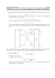
Generation of LSB SSB Using Wideband Low-Pass Filter<br />
DSB Spectrum<br />
H L (f)<br />
f c<br />
SSB Spectrum<br />
f c<br />
f c<br />
f c<br />
H L (f)<br />
sgn(f f c )<br />
sgn(f + f c )
Generation of USB SSB Using High-Pass (or Passband)<br />
Filter<br />
DSB Spectrum<br />
H HP (f)<br />
f c<br />
SSB Spectrum<br />
f c<br />
f c<br />
f c<br />
H HP (f) = sgn(f + f c ) + sgn(f + f c )<br />
sgn(f + f c )<br />
sgn(f f c )
SSB Modulated Wave<br />
• Lower <strong>Sideband</strong> SSB<br />
s LSB (t) = 1 2 m(t) cos(2 f ct)+ 1 2 ˆm(t)sin(2 f ct)<br />
• Upper sideband SSB<br />
s USB (t) = 1 2 m(t) cos(2 f ct)<br />
1<br />
2 ˆm(t)sin(2 f ct)
Applications of SSB and Difficulties in Implementing SSB<br />
• Two difficulties of SSB modulations<br />
• Designing and implementing the sharp Low-pass (or High-pass/pass-band)<br />
filter is not easy for circuit designer.<br />
• Hence, the message signal which does not contain the significant energy in<br />
the DC area is often modulated by the SSB such as the speech signal.<br />
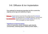
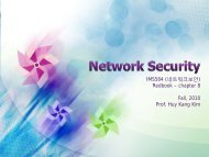
Spectrum of Speech Signal (Example)<br />
0 [Hz]<br />
• However, the SSB cannot be applicable for the message signal which<br />
contains the significant energy around zero frequency such as video<br />
signal, computer data, and etc.
<strong>Vestigial</strong> <strong>Sideband</strong> (VSB) <strong>Modulation</strong><br />
• VSB <strong>Modulation</strong><br />
• <strong>Modulation</strong> to overcome the two difficulties of the SSB modulations.<br />
• Allow a small amount, or vestige, of the unwanted sideband to appear at<br />
the output of an SSB modulator<br />
• The design of the sideband filter is simplified since the need for sharp<br />
cutoff at the carrier frequency is eliminated.<br />
• In addition, a VSB system has improved low-frequency response and<br />
can even have dc response.
Idea of VSB Modulator<br />
• Pass-band (or High-pass) filter for USB-SSB modulation<br />
|H U (f)|<br />
f c<br />
f c<br />
• The filter below is much easier to design and implement<br />
1 ✏ 1 1<br />
✏<br />
f c f 1<br />
f c<br />
f c + f 1
• Consider the two-tone message signal given as<br />
m(t) =A cos(2 f 1 t)+B cos(2 f 2 t)<br />
• Message signal multiplied by the carrier wave, that is, DSB signal<br />
e DSB (t) = (A cos(2 f 1 t)+B cos(2 f 2 t)) · cos(2 f c t)<br />
= 1 2 A cos(2 (f c + f 1 )t)+ 1 2 A cos(2 (f c f 1 )t)<br />
+ 1 2 B sin(2 (f c + f 1 )t)+ 1 2 B sin(2 (f c f 1 )t)
• Spectrum of DSB signal<br />
1<br />
2 B 1<br />
1<br />
2 A 1<br />
2 A 2 B<br />
• Frequency response of the VSB filter<br />
f c f 2 f c f 1 f<br />
f c + f 1 f c + f 2<br />
c<br />
1 ✏ 1 ✏<br />
f c<br />
• Output response<br />
s(t) = 1 2 A cos(2⇥(f c f 1 )t)<br />
+ 1 2 A(1 ) cos(2⇥(f c + f 1 )t)<br />
+ 1 2 B cos(2⇥(f c + f 2 )t)<br />
f c f 1<br />
f c + f 1<br />
f c + f 2<br />
1<br />
1<br />
1<br />
2 A 2 [A(1 )] 2 B<br />
f c f 1 f c + f 1<br />
f c f 2<br />
f c + f 2
Demodulation of VSB Signal (Coherent method)<br />
• Downconvert (by Multiplying 4 cos(2 f c t) ) and low pass filtering<br />
• Downconvert<br />
d(t) = s(t) · 4 cos(2⇥f c t)<br />
= 1 2 A cos(2⇥(f c f 1 )t) · 4 cos(2⇥f c t)<br />
+ 1 2 A(1 ) cos(2⇥(f c + f 1 )t) · 4 cos(2⇥f c t)<br />
+ 1 2 B cos(2⇥(f c + f 2 )t) · 4 cos(2⇥f c t)<br />
cos(2 (f c + f 1 )t) · cos(2 f c t)= 1 apple<br />
cos(2 (2f c + f 1 )t) + cos(2 f 1 t)<br />
2<br />
Low-Pass Filtering<br />
1<br />
2 cos(2 f 1t)
• Signal after Low-pass filtering<br />
⇥(t) = A cos(2⇤f 1 t)+A(1 ) cos(2⇤f 1 t)+B cos(2⇤f 2 t)<br />
= A cos(2⇤f 1 t)+B cos(2⇤f 2 t)
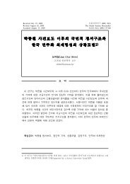
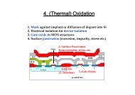
Television Signals<br />
[Ref: Haykin & Moher, Textbook]
Baseband Representation of Modulated Waves<br />
• DSB modulated wave signal<br />
s DSB (t) =Am(t) cos(2 f c t)<br />
• SSB modulated wave signal<br />
s SSB (t) = 1 2 Am(t) cos(2 f ct) ± 1 2 A ˆm(t)sin(2 f ct)<br />
• In general, we can write the “linear modulated wave” as<br />
s(t) =s I (t) cos(2 f c t) s Q (t)sin(2 f c t)<br />
Carrier wave with frequencyf c<br />
quadrature-phase version of the carrier<br />
c(t) = cos(2 f c t) ĉ(t) =sin(2 f c t)<br />
Orthogonal each other
• We can rewrite the modulated wave as<br />
s(t) =s I (t)c(t)<br />
s Q (t)ĉ(t)<br />
in-phase component of s(t)<br />
quadrature(-phase) component of s(t)<br />
• Introduce the complex envelop of the modulated wave s(t)<br />
˜s(t) =s I (t)+js Q (t)<br />
• Define the complex carrier wave<br />
˜c(t) =c I (t)<br />
jc Q (t)
• Consider the following<br />
˜s(t) · exp(j2 f c t) =<br />
apple<br />
s I (t)+js Q (t) ·<br />
apple<br />
cos(2 f c t)+j sin(2 f c t)<br />
• Real term<br />
apple<br />
⇥ ˜s(t) · exp(j2 f c t) = s I (t) · cos(2 f c t) s Q (t) · sin(2 f c t)<br />
• Imaginary term<br />
apple<br />
˜s(t) · exp(j2 f c t) = s I (t)sin(2 f c t)+s Q (t) cos(2 f c t)<br />
˜s(t)<br />
X<br />
apple<br />
· s(t)<br />
exp(j2 f c t)
• Now consider<br />
˜s(t) =s I (t)+js Q (t) =a(t)e j (t)<br />
where<br />
a(t) =<br />
q<br />
s 2 I (t)+js2 Q (t),<br />
(t) = tan 1 s Q(t)<br />
s I (t)<br />
• Then we can represent the modulated wave as<br />
apple<br />
s(t) = <<br />
apple<br />
= <<br />
˜s(t)e j2⇥f ct<br />
a(t)e j[2⇥f ct+ (t)]<br />
= a(t) cos[2⇥f c t + (t)]<br />
apple<br />
= < a(t)e j (t) e j2⇥f ct
• Three different representation of modulated wave using its equivalent<br />
baseband signal<br />
s(t) = s I (t) cos(2⇥f c t) s Q (t)sin(2⇥f c t)<br />
apple<br />
= < ˜s(t)e j2 f ct<br />
= a(t) cos[2⇥f c t + (t)]
Superheterodyne Receiver<br />
[Ref: Haykin & Moher, Textbook]
Communication Chipset Architecture<br />
LNA<br />
Receiver<br />
÷ 2<br />
PLL<br />
ABB Section<br />
90<br />
0<br />
antenna<br />
switch<br />
90<br />
0<br />
÷ 2<br />
PLL<br />
ABB<br />
Digital<br />
Baseband<br />
IC<br />
Power<br />
Amplifier<br />
Switchplexer<br />
Transmitter<br />
module<br />
PA Ctrl<br />
26MHz Osc.<br />
LDO’s
Frequency-Division Multiplexing<br />
• To transmit a number of communication signals over the same channel, the<br />
signals must be kept apart so that they do not interfere with each other, and<br />
thus they can be separated at the receiving end.<br />
• FDM (Frequency division multiplexing)<br />
• TDM (Time division multiplexing)<br />
• SDM (Space division multiplexing)<br />
• CDM (Code division multiplexing)
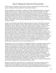
Block Diagram of FDM
Angle <strong>Modulation</strong><br />
• Basic Definition of Angle <strong>Modulation</strong><br />
s(t) =A c cos[ i (t)] = A c cos[2⇥f c t + ⇤ c ]<br />
• Phase modulation (PM) if<br />
i(t) =2⇥f c t + k p m(t)<br />
• Frequency modulation (FM) if<br />
Z t<br />
i(t) =2⇥f c t +2⇥k f m(⇤) d⇤<br />
0