Pipework Dampers
Pipework Dampers
Pipework Dampers

Create successful ePaper yourself
Turn your PDF publications into a flip-book with our unique Google optimized e-Paper software.
Schwingungsisolierungen<br />
<strong>Pipework</strong> <strong>Dampers</strong><br />
Technical Report<br />
July 1997<br />
Dr. Frank Barutzki<br />
Dr. Karl-Heinz Reinsch<br />
————————————————————————————————————————————————————————————————————————<br />
GERB Schwingungsisolierungen Telefon 0 30/41 91-0 Kommanditgesellschaft: Geschäftsführer:<br />
GmbH & Co. KG Telefax 0 30/41 91-199 HR Berlin-Charlottenburg Nr. A 1493 Horst Schmidt<br />
Roedernallee 174-176 E-Mail iso@gerb.de Komplementär: GERB Schwingungsisolierungen Ehrenfried von Waldow<br />
13407 Berlin, Deutschland Internet www.gerb.com Verwaltungsgesellschaft mbH, Berlin Dr. Armin Winkler<br />
Postfach 51 02 30, 13362 Berlin USt-IdNr. DE136650801 HR Berlin-Charlottenburg Nr. B 1034
TABLE OF CONTENTS<br />
GERB Innovations...........................................................................................................................................................................................................................................................3<br />
1 Vibration Isolation - Vibration Damping....................................................................................................................................4<br />
2 Design, Reaction and Properties of <strong>Pipework</strong> <strong>Dampers</strong>..............................................5<br />
3 Range and Limits of <strong>Pipework</strong> Damper Applications.............................................................8<br />
4 Characteristics...............................................................................................................................................................................................................................................................................9<br />
4.1 Nominal Load...................................................................................................................................................................................................................................................................................................9<br />
4.2 Damping Resistance............................................................................................................................................................................................................................................................10<br />
4.3 Equivalent Stiffness.................................................................................................................................................................................................................................................................12<br />
4.4 Operating Temperature................................................................................................................................................................................................................................................14<br />
Temperature Dependent Viscoliquid..................................................................................................................................................................................14<br />
Nearly Temperature Independent Viscoliquid............................................................................................................................................16<br />
Viscoliquid with Limited Dependency on Temperature......................................................................................................16<br />
4.5 Permissible Displacements ..............................................................................................................................................................................................................................17<br />
5 Design.......................................................................................................................................................................................................................................................................................................................19<br />
5.1 Strength........................................................................................................................................................................................................................................................................................................................19<br />
5.2 Materials....................................................................................................................................................................................................................................................................................................................21<br />
5.3 Tolerances ..........................................................................................................................................................................................................................................................................................................21<br />
5.4 Surface..........................................................................................................................................................................................................................................................................................................................21<br />
5.5 Production............................................................................................................................................................................................................................................................................................................21<br />
5.6 Test Procedures, Quality Assurance...................................................................................................................................................................................22<br />
TÜV Certification...................................................................................................................................................................................................................................................................22<br />
Foreign Certifications.................................................................................................................................................................................................................................................22<br />
KTA-Rules...............................................................................................................................................................................................................................................................................................23<br />
Certificate about Radiation Resistance......................................................................................................................................................................23<br />
6 Limits in Operation.................................................................................................................................................................................................................................................23<br />
6.1 Loading of the Sub- and Superstructure....................................................................................................................................................................23<br />
Static Loads.......................................................................................................................................................................................................................................................................................23<br />
Quasi-static Loads ...........................................................................................................................................................................................................................................................23<br />
Dynamic Loads ..........................................................................................................................................................................................................................................................................24<br />
6.2 Loading of the <strong>Pipework</strong> Damper...............................................................................................................................................................................................25<br />
6.3 Radiation Resistance.........................................................................................................................................................................................................................................................26<br />
6.4 Temperature Limits...................................................................................................................................................................................................................................................................26<br />
6.4.1 Temperatures During Operation........................................................................................................................................................................................................26<br />
6.4.2 Flashpoint and Ignition Temperature....................................................................................................................................................................................26<br />
6.4.3 Heat Conductivity...........................................................................................................................................................................................................................................................................26<br />
6.5 Environmental Influences.........................................................................................................................................................................................................................................27<br />
Moisture........................................................................................................................................................................................................................................................................................................27<br />
Aggressive Liquids, Acids, Lyes...................................................................................................................................................................................................27
7 Selection of <strong>Pipework</strong> <strong>Dampers</strong>..........................................................................................................................................................................28<br />
7.1 Operating Temperature................................................................................................................................................................................................................................................28<br />
7.2 Heat Expansion of the Piping System.............................................................................................................................................................................29<br />
<strong>Pipework</strong> <strong>Dampers</strong> Type RRD..TU, RHY, VES (VRD), RRD.........................................................................29<br />
7.3 Dynamic Reaction of the Piping System.................................................................................................................................................................30<br />
7.3.1 Reaction of <strong>Pipework</strong> <strong>Dampers</strong> to Shock-type Piping Excitation.................................................30<br />
Selection of <strong>Pipework</strong> <strong>Dampers</strong> without Analysis of the Piping System.............................30<br />
Selection of <strong>Pipework</strong> <strong>Dampers</strong> with Analysis of the Piping System..........................................31<br />
Modal Flow Analysis at Design Stage..........................................................................................................................................................................33<br />
- for Subsequent Installation of <strong>Pipework</strong> <strong>Dampers</strong>.................................................................................................................34<br />
7.3.2 Damping of Operational Vibrations..........................................................................................................................................................................................34<br />
Selection of <strong>Pipework</strong> <strong>Dampers</strong> without Analysis of the Piping System.............................34<br />
Selection of <strong>Pipework</strong> <strong>Dampers</strong> with Analysis of the Piping System..........................................35<br />
7.3.3 Examples for the Selection of <strong>Pipework</strong> <strong>Dampers</strong>....................................................................................................................36<br />
8 <strong>Pipework</strong> <strong>Dampers</strong> Program..............................................................................................................................................................................................38<br />
8.1 Standard <strong>Pipework</strong> <strong>Dampers</strong>......................................................................................................................................................................................................................38<br />
<strong>Pipework</strong> <strong>Dampers</strong> Type VES, VRD, RRD.....................................................................................................................................................39<br />
<strong>Pipework</strong> <strong>Dampers</strong> Type RHY, RRD..TU............................................................................................................................................................40<br />
8.2 Supply Details ...........................................................................................................................................................................................................................................................................................41<br />
8.3 Spare Parts and Accessories ...................................................................................................................................................................................................................41<br />
Sleeves ...........................................................................................................................................................................................................................................................................................................41<br />
Viscoliquid, Heater Sleeves, Fixing Bolts...............................................................................................................................................................42<br />
9 Guidelines for Transport.................................................................................................................................................................................................................42<br />
10 Guidelines for Installation.........................................................................................................................................................................................................43<br />
10.1 Information for the <strong>Pipework</strong> Designer..........................................................................................................................................................................43<br />
Design/Rigidity of the Connecting Structures .............................................................................................................................................43<br />
10.2 Information for the Installation Team...................................................................................................................................................................................45<br />
Eccentrically Pre-Set <strong>Pipework</strong> <strong>Dampers</strong>...........................................................................................................................................................45<br />
Tightening Torque for the Recommended Bolt Sizes............................................................................................................46<br />
10.3 Repair of <strong>Pipework</strong> <strong>Dampers</strong> ....................................................................................................................................................................................................................46<br />
10.3.1 Replacement of the Viscoliquid...........................................................................................................................................................................................................46<br />
10.3.2 Replacement of the Sleeve..............................................................................................................................................................................................................................47<br />
11 Guideline for Inspections............................................................................................................................................................................................................48<br />
12 Guideline for Disposal .............................................................................................................................................................................................................................49<br />
13 Literature.......................................................................................................................................................................................................................................................................................................50<br />
14 Appendix.......................................................................................................................................................................................................................................................................................................52<br />
VES Damper Parameters......................................................................................................................................................................................................53 - 56<br />
Safety Instructions............................................................................................................................................................................................................................................................57<br />
Material Safety Datasheet......................................................................................................................................................................................................58 - 60<br />
<strong>Pipework</strong> Damper Tests ...................................................................................................................................................................................................................................61
GERB Innovations<br />
GERB Vibration Control Systems was founded in 1907 to provide vibration and structure-borne<br />
noise control for machinery and other equipment.<br />
GERB has published many papers and has received many patents over the decades.<br />
The pipework damper is an off-shoot of standard Viscodampers, which have been used for more<br />
than 50 years parallel to helical spring systems in machine foundation support. The development of<br />
pipework dampers in the seventies started with the request of power plant customers to provide a low<br />
price and maintenance-free replacement of snubbers without the well-known disadvantages of those<br />
elements.<br />
The development took several years and ended in 1981 in a first TÜV certification, which allows the<br />
application of pipework dampers in nuclear plants as standard elements.<br />
Different to standard pipework dampers below machine foundations, the pipework damper has to<br />
take heat expansion, has to stay functional at high temperatures, and should provide typically higher<br />
damping. In a response to special requests of pipework designers, pipework dampers are<br />
continuously further developed. This relates, for example, to<br />
− improving and adapting the selection methods to the latest dynamic analysis methods for<br />
piping systems,<br />
− changes in the Viscoliquid as far as temperature dependency, load capacity, and<br />
tolerances in the damping resistance are concerned,<br />
− pipework dampers specially designed, for example, for high heat expansion.<br />
GERB will always accept ideas, which may lead to an improvement of the product or this technical<br />
documentation.
1 Vibration Isolation - Vibration Damping<br />
Certain basic knowledge of vibration control is necessary to understand dampers and how they work<br />
in general and especially pipework dampers. This includes the difference between vibration isolation<br />
and vibration damping.<br />
Vibration isolation reduces the transmission of shock-type, random, or periodical dynamic loads to<br />
protect the surroundings from, for example, a machine causing such dynamic loads (active isolation)<br />
or to protect a building or a sensitive machine against incoming vibrations (passive isolation). In both<br />
cases the system is placed on springs or other elastic elements.<br />
A machine on a conventional foundation will send its dynamic loads unaffected into the ground. In<br />
elastically supported equipment, a major part of those dynamic loads is transferred into kinetic<br />
energy causing periodical motion of that equipment, while only a minor percentage of the dynamic<br />
loads is transmitted via the springs. One of the main requirements in the design of vibration control<br />
systems for equipment is to keep its motion in permissible limits during operation. This requirement<br />
can be achieved by either adding mass to the system or by additional damping.<br />
Damping will transfer part of the dynamic energy into heat, but depending on the amount of critical<br />
damping for the system, dampers will also transmit dynamic loads, something what pure elastic<br />
support wants to prevent. The efficiency of a vibration control system is, therefore, influenced by<br />
damping and vibration control, in reality a compromise between the transmission of dynamic loads<br />
and permissible motion of the elastically supported system.<br />
In a typical GERB system, helical springs provide the elasticity while damping is provided by<br />
separate Viscodampers. This permits a perfect fine-tuning of parameters stiffness and damping.<br />
The design requirements for piping systems are different. Caused by periodical or shock excitation<br />
during normal operation or in emergency cases, the piping system may be damaged by resulting nonpermissible<br />
high dynamic displacements. <strong>Pipework</strong> dampers are designed to prevent such<br />
displacements in areas where heat expansion prevents fix points.<br />
Different to standard vibration control, forces transmitted from the piping system into the substructure<br />
are not reduced, only the dynamic displacements in the piping system itself will be limited to a<br />
permissible range. The loads transmitted from the piping via the pipework dampers into the<br />
substructure are here deliberately accepted.
2 Design, Reaction, and Properties of <strong>Pipework</strong> <strong>Dampers</strong><br />
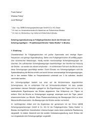
<strong>Pipework</strong> dampers consist of the housing, the Viscoliquid, and the piston (fig. 2.1). The piston,<br />
dipping into the Viscoliquid, can move in all directions. Damping is, therefore, possible in all six<br />
degrees of freedom.<br />
For small deflections, for example caused by operational vibrations, damper forces are a result of<br />
shearing the Viscoliquid. Friction between piston and Viscoliquid is of minor importance. Only in case<br />
of high deflections, for example as a result of heat expansion of the piping system, displacement<br />
effects will occur in addition.<br />
The damper forces<br />
F ≈ r x v (2.1)<br />
are proportional to the relative velocity v between the damper piston and the damper housing. The<br />
proportionality factor r (N/(m/s) = Ns/m) is called the damping resistance and depends on frequency<br />
r = r(f) (2.2)<br />
Since one damper part is usually not moving, calculations are based upon the absolute velocity of the<br />
damper piston or the damper housing and not upon the relative velocity between those two parts.<br />
damper piston<br />
Fig. 2.1 <strong>Pipework</strong> Damper<br />
Viscoliquid<br />
damper housing
Owing to the fact that pipework dampers react velocity-proportional, they cannot be used to support<br />
static loads.<br />
The most important properties of pipework dampers are:<br />
a) They respond without clearance, time delay, or minimal response deflection<br />
The damper piston is always in contact with the Viscoliquid so that the pipework damper<br />
responds as a support without clearance, time delay, or minimal deflection. Damping resistance<br />
is always proportional to the relative velocity between the damper piston and housing.<br />
b) High resistance under shock load<br />
The pipework damper develops a high resistance against high input velocities in emergency<br />
cases. Inadmissible deflections of the pipework, caused, for instance, by earthquakes, aircraft<br />
impact, or pressure pulses, are thus suppressed.<br />
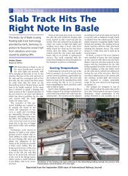
Since the pipework damper reacts without delay, reaction begins already in the initial phase of<br />
the shock parallel to the increasing shock velocity. This leads to a smooth reaction of the piping<br />
system. The pipework damper develops its energy dissipating properties already at a time where<br />
snubbers, for example, don’t yet react (fig. 2.2).<br />
Force<br />
Snubber<br />
<strong>Pipework</strong> Damper<br />
Time<br />
Fig. 2.2 Time/Force Reaction Diagram of Snubbers and <strong>Pipework</strong> <strong>Dampers</strong><br />
c) Transition from an emergency case to normal operation with no recovery time<br />
<strong>Pipework</strong> dampers will react to operational vibrations immediately after a case of emergency<br />
and permit motion of the pipework since the damper piston and the Viscoliquid always remain in<br />
contact. Since the elasticity of the piping system remains, secondary damage can be prevented<br />
and internal damping of the piping system can be used for additional energy dissipation.
d) Permissibility of overloading the Viscoliquid<br />
Even if the load limits are exceeded, the pipework damper will return to normal operation again<br />
after a brief regeneration period. Replacement of the Viscoliquid is not necessary.<br />
e) Damping of operational vibrations<br />
Modal system damping of piping systems is usually assumed to be 2 - 5 % of critical damping<br />
depending on different guidelines. <strong>Pipework</strong> dampers will provide in their locations additional<br />
velocity proportional damping. This will lead to an increased system damping, if type, size, and<br />
location of the pipework dampers are properly selected. <strong>Pipework</strong> dampers will, therefore, not<br />
only respond in emergency cases, but will also reduce operational vibrations.<br />
f) Low damper forces when subject to slow motion<br />
<strong>Pipework</strong> deflections resulting from thermal expansion are not restricted because of low<br />
expansion velocity.<br />
g) Reaction in all degrees of freedom<br />
<strong>Pipework</strong> dampers will react in all degrees of freedom at the same time. It is not necessary to<br />
use separate elements for different degrees of freedom.<br />
h) No requirement of maintenance<br />
<strong>Pipework</strong> dampers are expected to require no maintenance at least for a period of 40 years,<br />
because of their simple design and the lack of mechanical wear and tear parts. The Viscoliquid is<br />
resistant to aging for the same period.
3 Range and Limits of <strong>Pipework</strong> Damper Applications<br />
<strong>Pipework</strong> dampers can be used, because of their properties, to overcome numerous dynamic<br />
pipework problems, for example in a replacement of snubbers and in damping operational vibrations.<br />
Main application areas are condensate piping, feed-water piping, main steam lines, hydraulic piping,<br />
live steam lines, and dust channels of coal mills.<br />
The production is based on a QA system as well as on a performance certification by the German<br />
Technical Inspection Authority (TÜV) and the Swedish S.A., which permit the application of pipework<br />
dampers type VES as a standard component even in nuclear facilities.<br />
Standard pipework dampers are available for nominal loads up to 100 kN. Because of the reaction<br />
without time delay, it is possible to distribute dynamic loads on to several dampers. Single loads can<br />
be added in a linear way. Damping resistance, respectively the resulting system damping, depends<br />
on frequency.<br />
Different Viscoliquids are available with very low, limited, and high temperature dependency.<br />
Temperature dependent Viscoliquid will provide in the same size damper the highest damping. Liquid<br />
with low temperature dependency is, on the other hand, of low viscosity and will, therefore, lead<br />
typically to bigger dampers and more complicated systems.<br />
A major criteria in the selection of dampers with Viscoliquid of high temperature dependency is the so<br />
called operating temperature, which is the maximum temperature inside the Viscoliquid during<br />
continuous operation of the plant. It is typically much lower than the temperature inside the piping and<br />
depends in a major way on the ambient temperature.<br />
The Viscoliquid will be adapted to the operating temperature and can be selected for temperature<br />
dependent Viscoliquid in the temperature range between 20 °C and 80 °C in steps of 10 °C.<br />
Viscoliquid with limited temperature dependency can be used in the temperature range between<br />
-10 °C and 40 °C. <strong>Pipework</strong> dampers with nearly temperature independent properties are for<br />
applications in the temperature range between -30 °C and +130 °C.<br />
Standard pipework dampers will allow heat expansion of ± 40 mm in all directions, but special<br />
dampers have been developed, permitting horizontal direction deflections up to ± 120 mm. Other<br />
combinations of vertical and horizontal heat expansion will need a special design, which is usually<br />
possible.<br />
In case of high heat expansion, the operating temperature in the temperature dependent liquid should<br />
not be more than 20 °C above the start-up temperature, as otherwise very high loads in the<br />
connecting structure have to be expected during start-up. In case of high expansion velocities and<br />
high temperatures in the pipe, the connecting structure between piping and pipework damper should<br />
be designed in a way that as little heat as possible is transmitted from the pipe into the damper.