Vibration suppression of a 90-m-tall steel
Vibration suppression of a 90-m-tall steel
Vibration suppression of a 90-m-tall steel

Create successful ePaper yourself
Turn your PDF publications into a flip-book with our unique Google optimized e-Paper software.
The Eighth East Asia-Pacific Conference on Structural Engineering and Construction<br />
5-7 December 2001, Nanyang Technological University, Singapore<br />
VIBRATION SUPPRESSION OF A <strong>90</strong>-M-TALL STEEL STACK BY USING<br />
A HIGH-DAMPING TUNED MASS DAMPER<br />
Natthapong Areemit 1 , Pennung Warnitchai 2<br />
ABSTRACT: This paper presents an application <strong>of</strong> a pendulum tuned mass damper to suppress wind-induced<br />
oscillation <strong>of</strong> a <strong>90</strong>-m-<strong>tall</strong> <strong>steel</strong> stack in Rayong, Thailand. During the design phase, an analysis <strong>of</strong> wind-induced<br />
response <strong>of</strong> the stack was carried out, and it was found that unacceptably large sway motions <strong>of</strong> the stack could<br />
be developed even at low wind speeds due to vortex resonance. It was also found that the sway motions could be<br />
effectively suppressed by introducing sufficiently high additional damping to the stack. A pendulum Tuned Mass<br />
Damper (TMD) was then chosen as a vibration control device to be ins<strong>tall</strong>ed at the top <strong>of</strong> the stack. It consists <strong>of</strong><br />
a 3600-kg <strong>steel</strong> ring, three suspended wire ropes, and three viscous dampers. The damping ratio <strong>of</strong> TMD was<br />
intentionally set to a value much higher than the optimal one; this was to keep the relative motion between TMD<br />
and the stack within an acceptable limit and to make the performance <strong>of</strong> TMD less sensitive to the error in<br />
frequency tuning. Performance tests <strong>of</strong> the pendulum TMD were conducted before and after the ins<strong>tall</strong>ation to<br />
the stack. The tests before the ins<strong>tall</strong>ation indicated that the natural frequency <strong>of</strong> TMD varied significantly with<br />
the vibration level. This was caused by the change in effective pendulum arm length, and the mechanism was<br />
carefully investigated in details. The tests also revealed a viscoelastic effect <strong>of</strong> the dampers; the dampers not<br />
only added damping to the pendulum system but also shortened the natural period <strong>of</strong> the system. Despite the<br />
variation <strong>of</strong> natural frequency and the viscoelastic effect, the tests after the ins<strong>tall</strong>ation showed clearly that<br />
sufficiently high damping was added into the stack system.<br />
KEYWORDS: Tuned Mass Damper, Steel Stack, Vortex resonance, High Damping<br />
1. INTRODUCTION<br />
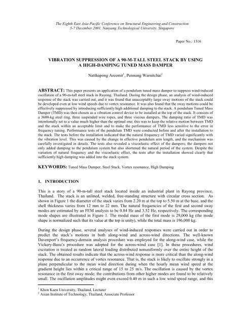
This is a story <strong>of</strong> a <strong>90</strong>-m-<strong>tall</strong> <strong>steel</strong> stack located inside an industrial plant in Rayong province,<br />
Thailand. The stack is an unlined, welded, free-standing structure with circular cross section. As<br />
shown in Figure 1 the diameter <strong>of</strong> the stack varies from 2.20 m at the top to 5.50 m at the base, and the<br />
shell thickness varies from 12 mm to 22 mm. The natural frequencies <strong>of</strong> the first and second sway<br />
modes are estimated by an FEM analysis to be 0.84 Hz and 3.52 Hz, respectively. The corresponding<br />
mode shapes are illustrated in Figure 1. The modal mass <strong>of</strong> the first mode is 29,000 kg (the mode<br />
shape is normalized such that its value at the top is unity), while the total mass is 196,000 kg.<br />
During the design phase, several analyses <strong>of</strong> wind-induced responses were carried out in order to<br />
predict the stack’s motions in both along-wind and across-wind directions. The well-known<br />
Davenport’s frequency-domain analysis procedure was employed for the along-wind case, while the<br />
Vickery-Basu’s procedure was adopted for the across-wind case [1]. In these procedures, wind<br />
excitation is treated as random lateral loading distributed nonuniformly over the entire height <strong>of</strong> the<br />
stack. The obtained results indicate that the across-wind response is more critical than the along-wind<br />
response due to an occurrence <strong>of</strong> vortex resonance. That is, the stack is likely to oscillate strongly in a<br />
plane perpendicular to the mean wind direction during when the hourly mean wind speed at the<br />
gradient height lies within a critical range <strong>of</strong> 15 to 25 m/s. The oscillation is caused by the vortex<br />
resonance in the first sway mode; the contributions from other higher modes are found to be relatively<br />
small. The oscillation amplitudes might even exceed 0.40 m in such a low wind speed range, and this<br />
1 Khon Kaen University, Thailand, Lecturer<br />
2 Asian Institute <strong>of</strong> Technology, Thailand, Associate Pr<strong>of</strong>essor<br />
Paper No.: 1316
could lead to an extremely high rate <strong>of</strong> fatigue damage accumulation and, consequently, an extremely<br />
short service life <strong>of</strong> the stack.<br />
The across-wind response analysis results show that the vortex-induced oscillation can be effectively<br />
suppressed by adding an additional damping to the stack. The damping <strong>of</strong> unlined, welded <strong>steel</strong> stacks<br />
reported in the literature normally lies within a range <strong>of</strong> 0.2 to 1.0 % <strong>of</strong> the critical damping, and this<br />
could lead to excessively high oscillation amplitudes as mentioned earlier. However, if the damping is<br />
raised to 2, 3, 4 and 5%, the maximum oscillation amplitude will be reduced to, approximately, 0.14,<br />
0.11, 0.09 and 0.08 m, respectively. It was considered that the damping <strong>of</strong> 2 % would be sufficient to<br />
ensure the safety and serviceability <strong>of</strong> the stack. This could be achieved by ins<strong>tall</strong>ing a properly<br />
designed Tuned Mass Damper (TMD) at the top <strong>of</strong> the stack.<br />
<strong>90</strong>.0 m<br />
10.0 m<br />
20.0 m<br />
30.0 m<br />
30.0 m<br />
2.20 m<br />
3.20 m<br />
4.10 m<br />
5.20 m<br />
(a) (b) (c)<br />
Figure 1 (a) A <strong>90</strong>-m-<strong>tall</strong> <strong>steel</strong> stack in Rayong, (b) its basic dimensions, and (c)the first and<br />
second sway vibration mode shapes<br />
2. DESIGN OF PENDULUM TUNED MASS DAMPER<br />
1 st Mode 2 nd Mode<br />
A simple pendulum-type TMD was chosen as a device to introduce the required additional damping to<br />
the stack. It consists <strong>of</strong> a <strong>steel</strong> ring, three suspended wire ropes, and three viscous dampers as shown in<br />
Figure 2. The design <strong>of</strong> this TMD was aiming at an additional damping <strong>of</strong> about 4 to 5 % <strong>of</strong> the<br />
critical value. In the initial design, the well-known optimal design formulas for the case where the<br />
main structure is subjected to stationary random loading were adopted [2]. The ring mass <strong>of</strong> 1500 kg<br />
was found to be sufficient, and the corresponding optimal damping ratio <strong>of</strong> TMD was estimated to be<br />
around 11 to 12 %. The optimal frequency tuning was achieved by setting the length <strong>of</strong> pendulum arm<br />
to 0.38 m. With this optimal design, an additional damping in excess <strong>of</strong> 5 % could be expected.<br />
However, the maximum relative movement between the ring and the stack was estimated to be as high<br />
as 0.32 m. Such a large relative movement could lead to several problems in the design <strong>of</strong> viscous<br />
dampers and could shorten the service life <strong>of</strong> suspended ropes. It was therefore considered that the<br />
maximum relative movement must be limited to 0.10 m.<br />
To satify this constraint, the initial design was adjusted by raising the TMD damping ratio to a level<br />
much higher than the optimal level and, at the same time, raising the ring mass to compensate the<br />
reduction in damper effectiveness. Note that the cost <strong>of</strong> TMD is not so sensitive to this adjustment<br />
because the additional material cost <strong>of</strong> the <strong>steel</strong> ring is relatively low and the cost <strong>of</strong> viscous dampers<br />
remain practically unchange for increasing levels <strong>of</strong> design damping coefficient. After a few rounds<br />
<strong>of</strong> design adjustment, the final design was obtained: the ring mass was set to 3600 kg, and the TMD<br />
damping ratio was set to 40 %. With this final design, an additional damping <strong>of</strong> about 5 to 6 % to the
stack can be expected, and the maximum relative movement is limited to 0.10 m as required. An<br />
additional benefit from this adjustment is the improved robustness <strong>of</strong> TMD; the performance <strong>of</strong> this<br />
high-damping TMD is less sensitive to the error in frequency tuning compared to the case <strong>of</strong> the initial<br />
design. This robustness is one <strong>of</strong> the key factors for the success in the application <strong>of</strong> this TMD—this<br />
point will be discussed in the following sections.<br />
(a) (b)<br />
(c) (d)<br />
Figure 2 Pendulum TMD and its components: (a) <strong>steel</strong> ring, (b) viscous damper, (c) suspended<br />
wire rope, (d) drawings showing the assembly<br />
3. PERFORMANCE TESTS<br />
A<br />
Stack<br />
Pendulum<br />
mass<br />
Stack<br />
Suspended cable<br />
Pendulum mass<br />
Damper<br />
Section A - A<br />
To ensure damper effectiveness, performance tests were carried out in six stages. The objective <strong>of</strong><br />
tests in the first three stages was to separately identify the dynamic properties <strong>of</strong> the pendulum TMD<br />
and the stack. The fourth-stage test was made to check the dynamic properties <strong>of</strong> the combined stack-<br />
TMD system. Tests in the last two stages were carried out to examine the control effectiveness <strong>of</strong><br />
TMD under normal service conditions.<br />
In the first stage, the pendulum system without viscous dampers was ins<strong>tall</strong>ed on the top segment <strong>of</strong><br />
the stack in the fabrication yard as shown in Figure 3. The segment was firmly locked to the floor, so<br />
that it acted like a motionless supporting frame for the pendulum. Two uniaxial acceleration sensors<br />
were placed on the ring to measure its motions in two horizontal orthogonal directions. The<br />
acceleration signals were recorded by a portable data acquisition unit. By this way, the natural<br />
frequency and damping ratio <strong>of</strong> the pendulum could be easily identified from its free vibration records.<br />
The obtained free vibration records indicate that vibration frequency is strongly dependent on<br />
vibration amplitude (Figure 4 a and b). This amplitude dependent characteristic could not be explained<br />
by the geometric nonlinearity <strong>of</strong> the pendulum, which causes almost negligibly small variation in<br />
vibration frequency within the measured amplitude range. It was observed, however, that when the<br />
vibration amplitude was small, the two ends <strong>of</strong> suspended ropes were practically clamped to the
support pins due to the friction between them (Figure 5b). But when the vibration amplitude was large,<br />
slips occurred at the contact points, and the rope ends rotated almost freely around the pins (Figure<br />
5c). By this mechanism, the effective pendulum arm length changed significantly during the decay <strong>of</strong><br />
free vibration, and so did the vibration frequency. The control effectiveness <strong>of</strong> TMD could be greatly<br />
affected by this frequency change if the damping ratio <strong>of</strong> TMD were set to the optimal level as in the<br />
initial design. Fortunately, in this case the damping ratio was set to such a high level that the<br />
effectiveness <strong>of</strong> TMD was rather insensitive to this frequency change.<br />
Acceleration, g<br />
0.50<br />
0.25<br />
0.00<br />
-0.25<br />
Figure 3 TMD ins<strong>tall</strong>ed on the top stack segment in the fabrication yard<br />
-0.50<br />
0.50<br />
0 10 20 30<br />
0.01 0.10 1.00<br />
Time, seconds<br />
Acceleration amp litude, g<br />
(a) (b)<br />
Figure 4 (a) Free vibration record <strong>of</strong> the pendulum system with no attached viscous dampers,<br />
and (b) computed vibration frequency from the record<br />
Frequency, Hz<br />
0.80<br />
0.70<br />
0.60<br />
a) b) c)<br />
Figure 5 Change in effective pendulum arm length
In the second stage, three viscous dampers were attached to the pendulum system, and free vibration<br />
test was carried out for this complete TMD configuration. It was found that, within the amplitude<br />
range <strong>of</strong> interest, the damping ratio was raised from 1–3 % to about 30 – 45 %, and the vibration<br />
frequency was also shifted from 0.61 – 0.67 Hz to about 0.78 – 0.88 Hz. The frequency shift could be<br />
explained by the fact that the viscous dampers generated not only viscous forces but also elastic<br />
forces; the dampers exhibited viscoelastic effect.<br />
In the third and fourth stage, free vibration tests were carried out after the construction <strong>of</strong> the stack<br />
was completed and TMD was ins<strong>tall</strong>ed on its top as designed. Acceleration sensors were placed on<br />
both stack and TMD. However, in the third stage the <strong>steel</strong> ring <strong>of</strong> TMD was locked such that it could<br />
not move relative to the stack; this was to check the dynamic properties <strong>of</strong> the stack. The sway motion<br />
<strong>of</strong> the stack was first induced by asking several people on the top platform to move their bodies back<br />
and forth in a synchronized manner at a frequency close to the estimated natural frequency. After a<br />
sufficiently high vibration amplitude had reached, these people were asked to stop moving their<br />
bodies, and the free vibration <strong>of</strong> the stack was measured and recorded. The vibration frequency and<br />
damping ratio <strong>of</strong> the stack were found to be 0.74 Hz and 0.7 %, respectively. After correcting for<br />
added masses <strong>of</strong> the ring and people, the natural frequency <strong>of</strong> the stack alone was estimated to be 0.80<br />
Hz, which was close to the computed value from FEM analysis.<br />
In the fourth stage, TMD was unlocked, and the same free vibration test was repeated. Comparing to<br />
the previous stage, the decay <strong>of</strong> stack’s motion is much faster as shown in Figure 6. The effective<br />
damping <strong>of</strong> the stack with TMD computed from this response was about 3.6 – 4.5 %, which was less<br />
than the expected figure—5 %, but it was high enough to prevent fatigue damage and extend the<br />
service life to an acceptable level.<br />
Acceleration, g<br />
0.20<br />
0.10<br />
0.00<br />
-0.10<br />
W ith unlocked TM D<br />
W ith locked TM D<br />
-0.20<br />
0 5 10<br />
Time, seconds<br />
15 20<br />
Figure 6 Free vibration responses <strong>of</strong> the stack with locked TMD and with unlocked TMD<br />
In the fifth and sixth stages, the responses <strong>of</strong> the stack with locked TMD and with unlocked TMD<br />
under natural wind excitation were measured in order to check the control performance in normal<br />
service conditions. The autocorrelation function <strong>of</strong> the random acceleration response <strong>of</strong> the stack in<br />
both stages looked like a cosine function <strong>of</strong> time with exponentially decreasing amplitude as expected.<br />
The decay rates showed that the effective damping <strong>of</strong> the stack increased from 0.5 % when TMD was<br />
locked to about 3.0% after TMD was unlocked. The effective damping was slightly lower than that<br />
obtained from free vibration tests. The difference was probably due to the fact that the level <strong>of</strong><br />
measured random responses was much lower than the level <strong>of</strong> free vibration responses (compare<br />
Figure 6 with Figure 7).
Acceleration, g<br />
0.004<br />
0.002<br />
0.000<br />
-0.002<br />
-0.004<br />
0 20 40 60 80 100<br />
Time, seconds<br />
Figure 7 Random vibration <strong>of</strong> the stack under natural wind<br />
Normalized autocorrelation function<br />
1.00<br />
0.10<br />
0.01<br />
With TMD<br />
W ith unlocked TMD<br />
ξ = 0.5 %<br />
0 10 20 30<br />
nth Cycle<br />
Figure 8 Autocorrelation envelope <strong>of</strong> the stack with locked TMD and with unlocked TMD<br />
4. CONCLUSIONS<br />
An application <strong>of</strong> TMD to suppress wind-induced vibration <strong>of</strong> the <strong>steel</strong> stack has been successfully<br />
carried out. The well-known optimal design theory for TMD could not be applied in this case. The<br />
damping ratio <strong>of</strong> TMD was instead set to a much higher level than the optimal value in order to keep<br />
the relative motion between TMD and the stack within an acceptable limit. This also made TMD more<br />
robust: the control effectiveness <strong>of</strong> this high-damping TMD was much less sensitive to the error in<br />
frequency tuning compared to the case <strong>of</strong> optimally designed TMD. The robustness was a crucial<br />
factor for the successful application <strong>of</strong> TMD because performance tests <strong>of</strong> TMD before the final<br />
ins<strong>tall</strong>ation showed that TMD’s frequency was strongly amplitude dependent. In addition, tests also<br />
revealed a viscoelastic effect <strong>of</strong> the viscous dampers; the dampers not only added damping to the<br />
pendulum system but also shortened its natural period. Despite the variation <strong>of</strong> natural frequency and<br />
the viscoelastic effect, performance tests after the ins<strong>tall</strong>ation <strong>of</strong> TMD showed clearly that sufficiently<br />
high damping has been successfully introduced into the stack.<br />
5. REFERENCES<br />
[1] Simiu, E., Scanlan, R.H., 1985, “Wind Effects <strong>of</strong> Structures: An Introduction to Wind<br />
Engineering”, 2 nd ed., NewYork, John Wile & Sons.<br />
[2] Fujino, Y., Abe, M., 1993, “Design Formulas for Tuned Mass Dampers based on a Perturbation<br />
Technique”, Earthquake Engineering and Strutural Dynamics, vol. 22, pp. 833-854.<br />
4.0 %<br />
3.0 %<br />
1.0 %<br />
2.0 %