Vibration suppression of a 90-m-tall steel
Vibration suppression of a 90-m-tall steel
Vibration suppression of a 90-m-tall steel

Create successful ePaper yourself
Turn your PDF publications into a flip-book with our unique Google optimized e-Paper software.
could lead to an extremely high rate <strong>of</strong> fatigue damage accumulation and, consequently, an extremely<br />
short service life <strong>of</strong> the stack.<br />
The across-wind response analysis results show that the vortex-induced oscillation can be effectively<br />
suppressed by adding an additional damping to the stack. The damping <strong>of</strong> unlined, welded <strong>steel</strong> stacks<br />
reported in the literature normally lies within a range <strong>of</strong> 0.2 to 1.0 % <strong>of</strong> the critical damping, and this<br />
could lead to excessively high oscillation amplitudes as mentioned earlier. However, if the damping is<br />
raised to 2, 3, 4 and 5%, the maximum oscillation amplitude will be reduced to, approximately, 0.14,<br />
0.11, 0.09 and 0.08 m, respectively. It was considered that the damping <strong>of</strong> 2 % would be sufficient to<br />
ensure the safety and serviceability <strong>of</strong> the stack. This could be achieved by ins<strong>tall</strong>ing a properly<br />
designed Tuned Mass Damper (TMD) at the top <strong>of</strong> the stack.<br />
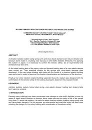
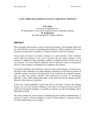
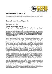
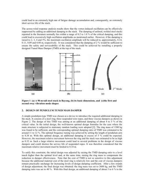
<strong>90</strong>.0 m<br />
10.0 m<br />
20.0 m<br />
30.0 m<br />
30.0 m<br />
2.20 m<br />
3.20 m<br />
4.10 m<br />
5.20 m<br />
(a) (b) (c)<br />
Figure 1 (a) A <strong>90</strong>-m-<strong>tall</strong> <strong>steel</strong> stack in Rayong, (b) its basic dimensions, and (c)the first and<br />
second sway vibration mode shapes<br />
2. DESIGN OF PENDULUM TUNED MASS DAMPER<br />
1 st Mode 2 nd Mode<br />
A simple pendulum-type TMD was chosen as a device to introduce the required additional damping to<br />
the stack. It consists <strong>of</strong> a <strong>steel</strong> ring, three suspended wire ropes, and three viscous dampers as shown in<br />
Figure 2. The design <strong>of</strong> this TMD was aiming at an additional damping <strong>of</strong> about 4 to 5 % <strong>of</strong> the<br />
critical value. In the initial design, the well-known optimal design formulas for the case where the<br />
main structure is subjected to stationary random loading were adopted [2]. The ring mass <strong>of</strong> 1500 kg<br />
was found to be sufficient, and the corresponding optimal damping ratio <strong>of</strong> TMD was estimated to be<br />
around 11 to 12 %. The optimal frequency tuning was achieved by setting the length <strong>of</strong> pendulum arm<br />
to 0.38 m. With this optimal design, an additional damping in excess <strong>of</strong> 5 % could be expected.<br />
However, the maximum relative movement between the ring and the stack was estimated to be as high<br />
as 0.32 m. Such a large relative movement could lead to several problems in the design <strong>of</strong> viscous<br />
dampers and could shorten the service life <strong>of</strong> suspended ropes. It was therefore considered that the<br />
maximum relative movement must be limited to 0.10 m.<br />
To satify this constraint, the initial design was adjusted by raising the TMD damping ratio to a level<br />
much higher than the optimal level and, at the same time, raising the ring mass to compensate the<br />
reduction in damper effectiveness. Note that the cost <strong>of</strong> TMD is not so sensitive to this adjustment<br />
because the additional material cost <strong>of</strong> the <strong>steel</strong> ring is relatively low and the cost <strong>of</strong> viscous dampers<br />
remain practically unchange for increasing levels <strong>of</strong> design damping coefficient. After a few rounds<br />
<strong>of</strong> design adjustment, the final design was obtained: the ring mass was set to 3600 kg, and the TMD<br />
damping ratio was set to 40 %. With this final design, an additional damping <strong>of</strong> about 5 to 6 % to the