Vibration suppression of a 90-m-tall steel
Vibration suppression of a 90-m-tall steel
Vibration suppression of a 90-m-tall steel

You also want an ePaper? Increase the reach of your titles
YUMPU automatically turns print PDFs into web optimized ePapers that Google loves.
stack can be expected, and the maximum relative movement is limited to 0.10 m as required. An<br />
additional benefit from this adjustment is the improved robustness <strong>of</strong> TMD; the performance <strong>of</strong> this<br />
high-damping TMD is less sensitive to the error in frequency tuning compared to the case <strong>of</strong> the initial<br />
design. This robustness is one <strong>of</strong> the key factors for the success in the application <strong>of</strong> this TMD—this<br />
point will be discussed in the following sections.<br />
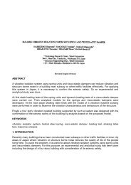
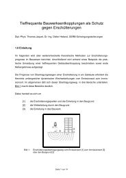
(a) (b)<br />
(c) (d)<br />
Figure 2 Pendulum TMD and its components: (a) <strong>steel</strong> ring, (b) viscous damper, (c) suspended<br />
wire rope, (d) drawings showing the assembly<br />
3. PERFORMANCE TESTS<br />
A<br />
Stack<br />
Pendulum<br />
mass<br />
Stack<br />
Suspended cable<br />
Pendulum mass<br />
Damper<br />
Section A - A<br />
To ensure damper effectiveness, performance tests were carried out in six stages. The objective <strong>of</strong><br />
tests in the first three stages was to separately identify the dynamic properties <strong>of</strong> the pendulum TMD<br />
and the stack. The fourth-stage test was made to check the dynamic properties <strong>of</strong> the combined stack-<br />
TMD system. Tests in the last two stages were carried out to examine the control effectiveness <strong>of</strong><br />
TMD under normal service conditions.<br />
In the first stage, the pendulum system without viscous dampers was ins<strong>tall</strong>ed on the top segment <strong>of</strong><br />
the stack in the fabrication yard as shown in Figure 3. The segment was firmly locked to the floor, so<br />
that it acted like a motionless supporting frame for the pendulum. Two uniaxial acceleration sensors<br />
were placed on the ring to measure its motions in two horizontal orthogonal directions. The<br />
acceleration signals were recorded by a portable data acquisition unit. By this way, the natural<br />
frequency and damping ratio <strong>of</strong> the pendulum could be easily identified from its free vibration records.<br />
The obtained free vibration records indicate that vibration frequency is strongly dependent on<br />
vibration amplitude (Figure 4 a and b). This amplitude dependent characteristic could not be explained<br />
by the geometric nonlinearity <strong>of</strong> the pendulum, which causes almost negligibly small variation in<br />
vibration frequency within the measured amplitude range. It was observed, however, that when the<br />
vibration amplitude was small, the two ends <strong>of</strong> suspended ropes were practically clamped to the