finite element analysis of stress stiffening effects in cmuts
finite element analysis of stress stiffening effects in cmuts
finite element analysis of stress stiffening effects in cmuts

Create successful ePaper yourself
Turn your PDF publications into a flip-book with our unique Google optimized e-Paper software.
Digital Object Identifier: 10.1109/ULTSYM.2008.0119<br />
FINITE ELEMENT ANALYSIS OF<br />
STRESS STIFFENING EFFECTS IN CMUTS<br />
Mario Kupnik, Ira O. Wygant, and Butrus T. Khuri-Yakub<br />
Edward L. G<strong>in</strong>zton Laboratory, Stanford University, Stanford, CA 94305-4088, USA<br />
Abstract—We use <strong>f<strong>in</strong>ite</strong> <strong>element</strong> <strong>analysis</strong> (FEA) to model<br />
capacitive micromach<strong>in</strong>ed ultrasonic transducer (CMUT)<br />
cells where <strong>stress</strong> <strong>stiffen<strong>in</strong>g</strong> affects static deflection, pull-<strong>in</strong><br />
voltage, resonance frequency, and small-signal sensitivity.<br />
Determ<strong>in</strong><strong>in</strong>g the small-signal sensitivity is challeng<strong>in</strong>g because<br />
it requires a pre<strong>stress</strong>ed harmonic response <strong>analysis</strong><br />
<strong>in</strong> which the geometric nonl<strong>in</strong>earities are activated dur<strong>in</strong>g<br />
the static <strong>analysis</strong> to pre<strong>stress</strong> the structure. The goal is a<br />
correct static operation po<strong>in</strong>t calculation for CMUT plates<br />
that exceed a static deflection-to-thickness ratio <strong>of</strong> 20%.<br />
Assum<strong>in</strong>g only a small AC excitation, we use a l<strong>in</strong>ear<br />
but updated stiffness matrix to calculate the harmonic<br />
response. We achieve this by us<strong>in</strong>g a pre<strong>stress</strong>ed mode<br />
superposition harmonic response <strong>analysis</strong>, which uses the<br />
sum <strong>of</strong> factored mode shapes obta<strong>in</strong>ed from a nonl<strong>in</strong>ear<br />
pre<strong>stress</strong>ed modal <strong>analysis</strong>. We test our FEA for two<br />
CMUTs, <strong>of</strong> which one operates <strong>in</strong> a more membranedom<strong>in</strong>ated<br />
regime. Comparisons to measurements demonstrate<br />
that only the FEA that accounts for <strong>stress</strong> <strong>stiffen<strong>in</strong>g</strong><br />
features good agreement for both designs. Our FEA allows<br />
us to model CMUTs that operate <strong>in</strong> a more membranedom<strong>in</strong>ated<br />
regime.<br />
I. INTRODUCTION<br />
Interest<strong>in</strong>gly, the term membrane is the established<br />
name for the key component <strong>of</strong> a CMUT – the mov<strong>in</strong>g<br />
part <strong>of</strong> the CMUT cell. The term plate, however, is<br />
more appropriate because almost every demonstrated<br />
CMUT operates <strong>in</strong> a pure plate regime, <strong>in</strong> which the<br />
bend<strong>in</strong>g stiffness (out-<strong>of</strong>-plane <strong>stress</strong>) dom<strong>in</strong>ates both the<br />
static and dynamic behavior. Even CMUTs with vacuumsealed<br />
cavities, biased close to pull-<strong>in</strong> po<strong>in</strong>t, typically<br />
have deflection-to-thickness ratios less than 20% (limit<br />
<strong>of</strong> Kirchh<strong>of</strong>f’s l<strong>in</strong>ear plate bend<strong>in</strong>g theory [1]), which<br />
places them <strong>in</strong> the plate regime.<br />
Stress <strong>stiffen<strong>in</strong>g</strong> is a geometrical nonl<strong>in</strong>earity that<br />
needs to be considered for th<strong>in</strong> structures that, <strong>in</strong> addition<br />
to bend<strong>in</strong>g stiffness, also have axial stiffness [2]. Even<br />
for an ideal-clamped plate with uniform thickness that<br />
experiences a large deflection due to a uniform load, the<br />
calculation <strong>of</strong> the deflection is complicated. The exact<br />
calculation <strong>of</strong> the deflection <strong>of</strong> the plate requires the<br />
knowledge <strong>of</strong> the <strong>stress</strong>-state <strong>of</strong> the plate, which <strong>in</strong> turn<br />
depends on the deflection. This leads to a nonhomogeneous<br />
system <strong>of</strong> equations (Karman equations, [3], [4])<br />
that can only be attacked by successive approximation<br />
techniques.<br />
There are several <strong>f<strong>in</strong>ite</strong> <strong>element</strong> s<strong>of</strong>tware packages<br />
that are useful for the CMUT design process. ANSYS,<br />
CAPA, COMSOL, PZFlex, and COVENTOR are examples.<br />
All <strong>of</strong> these s<strong>of</strong>tware packages provide the required<br />
<strong>analysis</strong> types for a successful CMUT design: a static<br />
structural <strong>analysis</strong> to calculate the static deflection and<br />
<strong>stress</strong> state <strong>of</strong> the CMUT plate; a modal <strong>analysis</strong> to<br />
calculate the natural frequencies and mode shapes <strong>of</strong><br />
the CMUT plate; a harmonic response <strong>analysis</strong> to calculate<br />
the dynamic response for susta<strong>in</strong>ed cyclic load<strong>in</strong>g<br />
conditions; and a transient dynamic <strong>analysis</strong> to calculate<br />
the dynamic response to general time-dependent load<strong>in</strong>g<br />
conditions.<br />
For a CMUT plate, above a vacuum gap and biased<br />
with a bias voltage V DC , the harmonic response <strong>analysis</strong><br />
as well as the modal <strong>analysis</strong>, only make sense when<br />
follow<strong>in</strong>g a static structural <strong>analysis</strong> (pre<strong>stress</strong>ed <strong>analysis</strong><br />
[5]). In case <strong>of</strong> the transient dynamic <strong>analysis</strong>, the static<br />
operation po<strong>in</strong>t needs to be taken <strong>in</strong>to account by correct<br />
static pressure and DC voltage load<strong>in</strong>g, before the ma<strong>in</strong><br />
transient excitation signal <strong>of</strong> <strong>in</strong>terest can be applied.<br />
Dur<strong>in</strong>g the FEA-based design process <strong>of</strong> the CMUT,<br />
only the harmonic response <strong>analysis</strong> and the transient<br />
dynamic <strong>analysis</strong> allow direct performance comparisons<br />
between different design iterations. Examples are the<br />
calculation <strong>of</strong> displacement, acoustic output pressure,<br />
electrical <strong>in</strong>put impedance, and receive and transmit<br />
sensitivity. The transient dynamic <strong>analysis</strong>, however,<br />
requires significant more computation time compared to<br />
a harmonic response <strong>analysis</strong>, <strong>in</strong> particular for systems<br />
with large quality factors. The measured quality factors<br />
for the displacement <strong>of</strong> the devices considered <strong>in</strong> this<br />
work are <strong>in</strong> the range <strong>of</strong> hundred to several hundreds.<br />
Although for circular shaped cells the axial symmetry<br />
can be exploited by us<strong>in</strong>g 2D models, these quality<br />
factors limit the transient dynamic <strong>analysis</strong> to impulse<br />
response calculations. For example, if one wants to<br />
978-1-4244-2480-1/08/$25.00 ©2008 IEEE 487 2008 IEEE International Ultrasonics Symposium Proceed<strong>in</strong>gs
calculate the response to burst or CW signals, f<strong>in</strong>d<strong>in</strong>g the<br />
exact excitation frequency for determ<strong>in</strong><strong>in</strong>g the maximum<br />
displacement is a challenge.<br />
Therefore, after discuss<strong>in</strong>g nonl<strong>in</strong>ear static and nonl<strong>in</strong>ear<br />
modal <strong>analysis</strong> <strong>in</strong> the next section, we focus on a<br />
pre<strong>stress</strong>ed harmonic response calculation with nonl<strong>in</strong>ear<br />
static solution steps before we compare our simulation<br />
results to measurements.<br />
y<br />
(a)<br />
x<br />
x-constra<strong>in</strong>ed<br />
DOF<br />
x&y-constra<strong>in</strong>ed<br />
DOF<br />
Plane182<br />
Trans126<br />
Fluid29 set as<br />
absorb<strong>in</strong>g boundary<br />
II. STATIC AND MODAL ANALYSIS<br />
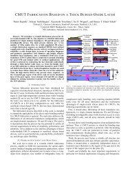
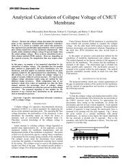
We use the s<strong>of</strong>tware package ANSYS to model <strong>stress</strong><br />
<strong>stiffen<strong>in</strong>g</strong> <strong>effects</strong> <strong>in</strong> CMUTs, ma<strong>in</strong>ly because <strong>of</strong> the<br />
availability <strong>of</strong> the lumped transducer <strong>element</strong> trans126<br />
(Fig. 1) [6].<br />
In this work, we consider two CMUT designs (A and<br />
B) for airborne ultrasound applications <strong>in</strong> the 50 kHz<br />
range [7]. Design A has a 40-µm-thick CMUT plate<br />
and a 36-µm gap; design B has a 60-µm-thick CMUT<br />
plate and a 16-µm gap. For both designs the plate<br />
material is s<strong>in</strong>gle crystal silicon, the plate diameter is<br />
4000 µm, and the <strong>in</strong>sulation layer (thermal grown silicon<br />
dioxide) thickness at the bottom <strong>of</strong> cavity is 3.3 µm.<br />
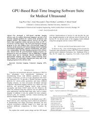
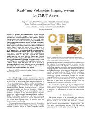
After the fabrication we compared the measured static<br />
plate deflections to the calculated ones, obta<strong>in</strong>ed from<br />
the FEM shown <strong>in</strong> Fig. 1(a). If <strong>stress</strong> <strong>stiffen<strong>in</strong>g</strong> <strong>effects</strong><br />
are not considered <strong>in</strong> the FEM (<strong>stress</strong> <strong>stiffen<strong>in</strong>g</strong> <strong>effects</strong><br />
turned <strong>of</strong>f, nlgeom command <strong>in</strong> ANSYS), only for the<br />
60-µm-thick plate, good agreement can be observed<br />
(Fig. 2).<br />
The design with the 40-µm-thick plate has a<br />
deflection-to-thickness ratio <strong>of</strong> more than 65%, i.e. this<br />
CMUT plate, <strong>in</strong> addition to bend<strong>in</strong>g stiffness, also is<br />
affected by membrane stiffness. Tensile membrane forces<br />
(plate is also stretched due to the deflection) lead to a<br />
reduced bend<strong>in</strong>g deformation. Fig. 2 confirms that our<br />
nonl<strong>in</strong>ear FEA shows good agreement for both designs.<br />
Stress <strong>stiffen<strong>in</strong>g</strong> not only affects the static behavior<br />
<strong>of</strong> the CMUT plate, it also <strong>in</strong>creases the resonance<br />
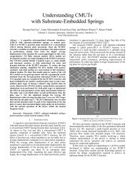
frequency <strong>of</strong> the device. For example, a l<strong>in</strong>ear and nonl<strong>in</strong>ear<br />
pre<strong>stress</strong>ed (pressure only) modal <strong>analysis</strong> for the<br />
(0,1) mode for plate thicknesses rang<strong>in</strong>g from 10 µm to<br />
90 µm (Fig. 3) illustrates why the deflection-to-thickness<br />
ratio is worth consider<strong>in</strong>g dur<strong>in</strong>g the design process.<br />
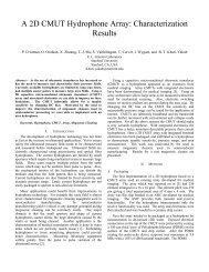
Another pre<strong>stress</strong>ed (pressure and bias voltage) modal<br />
<strong>analysis</strong> (Fig. 4), <strong>in</strong> which the bias voltage is varied from<br />
0 to 1100 V, demonstrates that besides <strong>in</strong>creas<strong>in</strong>g the<br />
resonance frequency, <strong>stress</strong> <strong>stiffen<strong>in</strong>g</strong> can dramatically<br />
<strong>in</strong>crease the pull-<strong>in</strong> voltage.<br />
y<br />
(b)<br />
x<br />
Air<br />
column<br />
Fluid29 with<br />
fluid-structure<br />
flag activated<br />
Fluid29<br />
Fig. 1. Schematics <strong>of</strong> the two <strong>f<strong>in</strong>ite</strong> <strong>element</strong> models (FEMs) for the<br />
calculation <strong>of</strong> the static, modal, and harmonic response <strong>of</strong> circular<br />
CMUT plates, <strong>in</strong>clud<strong>in</strong>g <strong>stress</strong> <strong>stiffen<strong>in</strong>g</strong> <strong>effects</strong>.<br />
III. HARMONIC RESPONSE CALCULATION WITH<br />
NONLINEAR STATIC SOLUTION STEP<br />
A harmonic response <strong>analysis</strong> is a small signal <strong>analysis</strong>,<br />
which is l<strong>in</strong>ear per def<strong>in</strong>ition. It is a ma<strong>in</strong> requirement<br />
that the structure has constant or frequency-dependent<br />
stiffness, damp<strong>in</strong>g, and mass <strong>effects</strong>. The pre<strong>stress</strong>ed<br />
harmonic response <strong>analysis</strong> requires two parts. First, a<br />
static solution needs to be obta<strong>in</strong>ed (pstres command <strong>in</strong><br />
ANSYS) and saved for the second subsequent part, the<br />
harmonic response <strong>analysis</strong>.<br />
As soon as geometrical nonl<strong>in</strong>earities are present <strong>in</strong><br />
the structure, the pre<strong>stress</strong>ed harmonic response <strong>analysis</strong><br />
is not possible per se. In case one turns on the geometrical<br />
nonl<strong>in</strong>earities dur<strong>in</strong>g the static <strong>analysis</strong>, ANSYS does<br />
not support the required subsequent harmonic response<br />
<strong>analysis</strong> and stops with the error message: “A pre<strong>stress</strong>ed<br />
<strong>analysis</strong> may not be performed when the previous <strong>analysis</strong><br />
used NLGEOM,ON.”<br />
For CMUT plates, which, <strong>in</strong> addition to bend<strong>in</strong>g stiffness,<br />
also are dom<strong>in</strong>ated by membrane stiffness, this is a<br />
major limitation. In such cases, the correct DC bias po<strong>in</strong>t<br />
488 2008 IEEE International Ultrasonics Symposium Proceed<strong>in</strong>gs
Deflection pr<strong>of</strong>ile (µm)<br />
5<br />
0<br />
-5<br />
-10<br />
-15<br />
-20<br />
-25<br />
-30<br />
-35<br />
60 µm-thick plate<br />
Gap for design A<br />
Gap for design B<br />
measured<br />
40 µm-thick plate, FEA with<br />
<strong>stress</strong> <strong>stiffen<strong>in</strong>g</strong> effect<br />
40 µm-thick plate, FEA without<br />
<strong>stress</strong> <strong>stiffen<strong>in</strong>g</strong> effect<br />
-40<br />
0 200 400 600 800 1000 1200 1400 1600 1800 2000<br />
Radial coord<strong>in</strong>ate (µm)<br />
Modal frequency <strong>of</strong> (0,1) mode (kHz)<br />
60<br />
55<br />
50<br />
45<br />
40<br />
35<br />
30<br />
25<br />
20<br />
15<br />
10<br />
40 µm, without<br />
<strong>stress</strong> <strong>stiffen<strong>in</strong>g</strong><br />
60 µm, without<br />
<strong>stress</strong> <strong>stiffen<strong>in</strong>g</strong><br />
60 µm, with<br />
<strong>stress</strong> <strong>stiffen<strong>in</strong>g</strong><br />
40 µm, with<br />
<strong>stress</strong> <strong>stiffen<strong>in</strong>g</strong><br />
5<br />
377 V 673 V 701 V 1016 V<br />
0<br />
0 100 200 300 400 500 600 700 800 900 1000 1100<br />
Bias voltage V DC<br />
(V)<br />
Fig. 2. Measured versus calculated plate deflection pr<strong>of</strong>iles for two<br />
designs A and B [7]. Design A has a deflection-to-thickness ratio <strong>of</strong><br />
65.2%, for B it is 15.2%.<br />
Fig. 4. Calculated modal frequency for mode (0,1) for design A<br />
and B as a function <strong>of</strong> the applied bias voltage V DC.<br />
Modal frequency <strong>of</strong> (0,1) mode (kHz)<br />
100<br />
90<br />
80<br />
70<br />
60<br />
50<br />
40<br />
30<br />
With<br />
<strong>stress</strong> <strong>stiffen<strong>in</strong>g</strong><br />
Without<br />
<strong>stress</strong> <strong>stiffen<strong>in</strong>g</strong><br />
Design A<br />
20<br />
10 20 30 40 50 60 70 80 90<br />
Plate thickness (µm)<br />
Design B<br />
V DC<br />
= 0 V<br />
Pressure = 1 atm<br />
Fig. 3. Calculated modal frequency for mode (0,1) <strong>of</strong> a circular<br />
s<strong>in</strong>gle crystal CMUT plate with a diameter <strong>of</strong> 4000 µm as a function<br />
<strong>of</strong> its thickness.<br />
calculation (static deflection due to atmospheric pressure<br />
and applied DC bias voltage) <strong>in</strong> the pre<strong>stress</strong><strong>in</strong>g step<br />
requires the nonl<strong>in</strong>earities to be turned on. If we assume<br />
the follow<strong>in</strong>g AC excitation to be small enough to result<br />
<strong>in</strong> small AC displacement <strong>of</strong> the CMUT plate only, we<br />
can argue that the <strong>stress</strong> state <strong>of</strong> the CMUT plate can<br />
be assumed to be constant around that DC operation<br />
po<strong>in</strong>t. This allows us to use a l<strong>in</strong>ear but updated stiffness<br />
matrix for the calculation <strong>of</strong> the harmonic response. The<br />
stiffness matrix is updated <strong>in</strong> terms <strong>of</strong> the static <strong>stress</strong><br />
state <strong>of</strong> the large deflected CMUT plate. Such a FEA that<br />
can perform a pre<strong>stress</strong>ed harmonic response calculation<br />
with a nonl<strong>in</strong>ear static solution step is required for<br />
CMUT designs when <strong>stress</strong>-<strong>stiffen<strong>in</strong>g</strong> <strong>effects</strong> are present.<br />
It will help predict the frequency response and allow<br />
performance comparisons <strong>of</strong> design variations <strong>in</strong> terms<br />
<strong>of</strong> transmit and receive sensitivity without runn<strong>in</strong>g a<br />
computationally <strong>in</strong>tensive transient <strong>analysis</strong>.<br />
In ANSYS we realized the pre<strong>stress</strong>ed harmonic response<br />
calculation with the nonl<strong>in</strong>ear static solution step<br />
by us<strong>in</strong>g a pre<strong>stress</strong>ed mode superposition harmonic<br />
response <strong>analysis</strong>. In this type <strong>of</strong> <strong>analysis</strong> the sum <strong>of</strong><br />
factored mode shapes (eigenvectors) obta<strong>in</strong>ed from a<br />
nonl<strong>in</strong>ear pre<strong>stress</strong>ed modal <strong>analysis</strong> is used to calculate<br />
the harmonic response. The procedure is as follows.<br />
First, a nonl<strong>in</strong>ear static deflection is calculated to pre<strong>stress</strong><br />
the structure. Then, a pre<strong>stress</strong>ed modal <strong>analysis</strong><br />
is performed to obta<strong>in</strong> all mode shapes <strong>in</strong> the frequency<br />
range <strong>of</strong> <strong>in</strong>terest. In the last step, the mode superposition<br />
harmonic solution is obta<strong>in</strong>ed by add<strong>in</strong>g all mode shapes.<br />
Such a pre<strong>stress</strong>ed mode superposition <strong>analysis</strong> cannot<br />
directly be applied to our problem statement <strong>of</strong> a CMUT<br />
plate mov<strong>in</strong>g <strong>in</strong> a medium, such as air or water, because<br />
<strong>of</strong> a limitation for the required pre<strong>stress</strong>ed modal <strong>analysis</strong><br />
step. The solid fluid <strong>in</strong>teraction will <strong>in</strong>troduce damp<strong>in</strong>g<br />
to the system, i.e. non-symmetric <strong>element</strong> matrices <strong>in</strong><br />
the FEM, which are not compatible with the only mode<br />
extraction method (QR damp mode extraction method<br />
[5]) that supports damp<strong>in</strong>g.<br />
We circumvent this problem by us<strong>in</strong>g both FEMs<br />
shown <strong>in</strong> Fig. 1. The second FEM has the solid fluid<br />
<strong>in</strong>teraction <strong>in</strong>cluded [Fig. 1(b)] and we use the waveguide<br />
approach as described <strong>in</strong> [8].<br />
Our procedure to calculate the pre<strong>stress</strong>ed harmonic<br />
response calculation with the nonl<strong>in</strong>ear static solution<br />
step is as follows: First, we use the FEM from Fig. 1(b)<br />
to calculate the pre<strong>stress</strong>ed harmonic response <strong>of</strong> the<br />
CMUT cell with a l<strong>in</strong>ear static solution step. The goal<br />
<strong>of</strong> this calculation is to determ<strong>in</strong>e the constant damp<strong>in</strong>g<br />
489 2008 IEEE International Ultrasonics Symposium Proceed<strong>in</strong>gs
Displacement at the center <strong>of</strong> the<br />
60-µm-thick plate (µm/V)<br />
1<br />
0.1<br />
0.01<br />
Without<br />
<strong>stress</strong> <strong>stiffen<strong>in</strong>g</strong><br />
1.46 µm/V<br />
at 49.2 kHz<br />
Q = 200<br />
With<br />
<strong>stress</strong> <strong>stiffen<strong>in</strong>g</strong><br />
1.35 µm/V<br />
at 51.3 kHz<br />
Q = 207<br />
Mode<br />
superposition<br />
harmonic<br />
Full harmonic and<br />
mode superposition harmonic give identical results<br />
V DC<br />
= 538 V<br />
V AC<br />
= 1 V<br />
1E-3<br />
10 20 30 40 50 60 70 80 90<br />
Frequency (kHz)<br />
(a)<br />
Displacement at the center <strong>of</strong> the<br />
40-µm-thick plate (µm/V)<br />
1<br />
0.1<br />
0.01<br />
Without<br />
<strong>stress</strong> <strong>stiffen<strong>in</strong>g</strong><br />
0.87 µm/V<br />
at 33.1 kHz<br />
Q = 93<br />
With<br />
<strong>stress</strong> <strong>stiffen<strong>in</strong>g</strong><br />
0.57 µm/V<br />
at 47.5 kHz<br />
Q = 131<br />
V DC<br />
= 300 V<br />
V AC<br />
= 1 V<br />
Mode<br />
superposition<br />
harmonic<br />
Full harmonic and<br />
mode superposition harmonic give identical results<br />
1E-3<br />
10 20 30 40 50 60 70 80 90<br />
Frequency (kHz)<br />
Fig. 5. Direct comparison for design B (left) and design A (right) <strong>of</strong> pre<strong>stress</strong>ed harmonic response <strong>analysis</strong> with l<strong>in</strong>ear static operation<br />
po<strong>in</strong>t calculation (blue) and pre<strong>stress</strong>ed mode superposition harmonic response <strong>analysis</strong> with nonl<strong>in</strong>ear static operation po<strong>in</strong>t calculation (red).<br />
(b)<br />
ratio ξ i = 1<br />
2Q i<br />
, where Q i is the quality factor at the resonance<br />
frequency ω i . The next step is to run a pre<strong>stress</strong>ed<br />
modal <strong>analysis</strong> with a nonl<strong>in</strong>ear static solution step to determ<strong>in</strong>e<br />
the resonance frequency ω j <strong>of</strong> the CMUT plate<br />
for the case when <strong>stress</strong> <strong>stiffen<strong>in</strong>g</strong> <strong>effects</strong> are present.<br />
By neglect<strong>in</strong>g mass damp<strong>in</strong>g <strong>effects</strong>, we can simply use<br />
the ratio ωj<br />
ω i<br />
as l<strong>in</strong>ear scal<strong>in</strong>g factor to determ<strong>in</strong>e the<br />
correspond<strong>in</strong>g constant damp<strong>in</strong>g ratio ξ j [5], because<br />
for this case the damp<strong>in</strong>g ratio is proportional to the<br />
natural frequency <strong>of</strong> the system. Then we can use ξ j <strong>in</strong><br />
comb<strong>in</strong>ation with the FEM from Fig. 1(a) to calculate<br />
the pre<strong>stress</strong>ed mode superposition harmonic response<br />
<strong>analysis</strong> with nonl<strong>in</strong>ear static solution step.<br />
IV. RESULTS<br />
As an example, we show the calculated center displacement<br />
for 1-V AC excitation for both designs<br />
(Fig. 5), biased at 80% <strong>of</strong> the pull-<strong>in</strong> voltage. Note<br />
that for the direct comparison (FEA with/without <strong>stress</strong><br />
<strong>stiffen<strong>in</strong>g</strong> <strong>effects</strong>) we had to use the pull-<strong>in</strong> voltage<br />
for the l<strong>in</strong>ear FEA (Fig. 4), otherwise the bias voltage<br />
would have been beyond the pull-<strong>in</strong> voltage for the<br />
l<strong>in</strong>ear case for design A. In both cases, we verified our<br />
FEA by compar<strong>in</strong>g the pre<strong>stress</strong>ed harmonic <strong>analysis</strong><br />
to the pre<strong>stress</strong>ed mode superposition harmonic <strong>analysis</strong><br />
for the l<strong>in</strong>ear cases. The curves overlap each other, as<br />
expected. For the nonl<strong>in</strong>ear cases, the direct comparison<br />
to the pre<strong>stress</strong>ed modal <strong>analysis</strong> (Fig. 3) shows<br />
excellent agreement <strong>in</strong> terms <strong>of</strong> the resonance frequency.<br />
Furthermore, our calculated center frequencies (51.3 kHz<br />
for design B, and 47.5 kHz for design A) show good<br />
agreement to the measured center frequencies (55 kHz<br />
for design B, and 46 kHz for design A [7]).<br />
V. CONCLUSION<br />
Only a model that considers <strong>stress</strong> <strong>stiffen<strong>in</strong>g</strong> <strong>effects</strong> is<br />
useful for the design <strong>of</strong> CMUTs that operate <strong>in</strong> a more<br />
membrane dom<strong>in</strong>ated regime. The key is a pre<strong>stress</strong>ed<br />
harmonic response calculation with a nonl<strong>in</strong>ear static solution<br />
step. Ignor<strong>in</strong>g <strong>stress</strong> <strong>stiffen<strong>in</strong>g</strong> leads to large errors<br />
<strong>in</strong> predicted static deflection, pull-<strong>in</strong> voltage, resonance<br />
frequency, and sensitivity.<br />
ACKNOWLEDGMENT<br />
The authors thank Dr. Evgeny Rudnyi and Dr. Laura<br />
Del T<strong>in</strong> for fruitful discussions.<br />
REFERENCES<br />
[1] E. Ventsel and T. Krauthammer, “Th<strong>in</strong> plates and shells,” 1st ed.,<br />
New York: Marcel Dekker, Inc., 2001.<br />
[2] E. S. Huang and S. D. Senturia, “Extend<strong>in</strong>g the travel range <strong>of</strong><br />
analog-tuned electrostatic actuators,” Journal <strong>of</strong> Microelectromechanical<br />
Systems, vol. 8, no. 4, pp. 497-505, 1999.<br />
[3] T. von Karman, “The eng<strong>in</strong>eer grapples with non-l<strong>in</strong>ear problems,”<br />
<strong>in</strong> Bull. Amer. Math. Soc., 1940, pp. 615–683.<br />
[4] S. Way, “Bend<strong>in</strong>g <strong>of</strong> circular plate with large deection,” <strong>in</strong> Trans.<br />
ASME, 1934, pp. 627–636.<br />
[5] ANSYS 11.0 Manual, Ansys Inc., Canonsburg, PA.<br />
[6] M. Gyimesi and D. Ostergaard, “Electro-mechanical capacitor<br />
<strong>element</strong> for MEMs <strong>analysis</strong> <strong>in</strong> ANSYS,” <strong>in</strong> Proc. Model<strong>in</strong>g and<br />
Simulation <strong>of</strong> Microsystems, 1999, pp. 270–273.<br />
[7] I. O. Wygant, M. Kupnik, J. C. W<strong>in</strong>dsor, W. M. Wright,<br />
G. Yaralioglu, M. S. Wochner, M. F. Hamilton, and B. T. Khuri-<br />
Yakub, “50-kHz capacitive micromach<strong>in</strong>ed ultrasonic transducers<br />
for generat<strong>in</strong>g highly directional sound with parametric arrays,”<br />
<strong>in</strong> Proc. IEEE Ultrason. Symp., 2007, pp. 519–522.<br />
[8] A. Lohf<strong>in</strong>k, P.-C. Eccardt, W. Benecke, and H. Meixner, “Derivation<br />
<strong>of</strong> a 1D CMUT model from FEM results for l<strong>in</strong>ear and<br />
nonl<strong>in</strong>ear equivalent circuit simulation,” <strong>in</strong> Proc. IEEE Ultrason.<br />
Symp., 2003, pp. 465–468.<br />
490 2008 IEEE International Ultrasonics Symposium Proceed<strong>in</strong>gs