Instructions - Classic Auto Air
Instructions - Classic Auto Air
Instructions - Classic Auto Air

You also want an ePaper? Increase the reach of your titles
YUMPU automatically turns print PDFs into web optimized ePapers that Google loves.
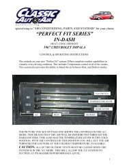
specializing in “AIR CONDITIONING, PARTS AND SYSTEMS” for your classic<br />
vehicle<br />
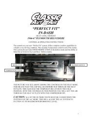
“PERFECT FIT SERIES”<br />
IN-DASH<br />
HEAT/ COOL/ DEFROST<br />
1966-67 CHEVROLET CHEVELLE/ EL CAMINO<br />
NOTE: INSTRUCTIONS DEPICT CHEVELLE<br />
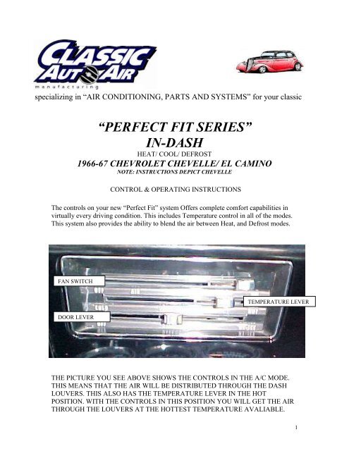
CONTROL & OPERATING INSTRUCTIONS<br />
The controls on your new “Perfect Fit” system Offers complete comfort capabilities in<br />
virtually every driving condition. This includes Temperature control in all of the modes.<br />
This system also provides the ability to blend the air between Heat, and Defrost modes.<br />
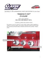
FAN SWITCH<br />
DOOR LEVER<br />
TEMPERATURE LEVER<br />
THE PICTURE YOU SEE ABOVE SHOWS THE CONTROLS IN THE A/C MODE.<br />
THIS MEANS THAT THE AIR WILL BE DISTRIBUTED THROUGH THE DASH<br />
LOUVERS. THIS ALSO HAS THE TEMPERATURE LEVER IN THE HOT<br />
POSITION. WITH THE CONTROLS IN THIS POSITION YOU WILL GET THE AIR<br />
THROUGH THE LOUVERS AT THE HOTTEST TEMPERATURE AVALIABLE.<br />
1
CAUTION: ALL OF THE OUTSIDE VENTS MUST BE CLOSED WHEN THE<br />
SYSTEM IS IN THE A/C MODE. THIS WILL ALLOW THE A/C SYSTEM TO<br />
FUCTION AT ITS MAXIMUM PERFORMANCE LEVEL.<br />
THE FOLLOWING SUMMARY WILL DESCRIBE EACH OF THE CONTROL<br />
LEVERS FUNCTION.<br />
FAN SPEED SWITCH: There are 3 speeds plus Off. When the switch is in the off<br />
position it will disconnect the 12V power to the Blower Motor and the A/C Clutch. This<br />
will shut down the entire system. When the switch is moved to any of the blower speeds<br />
1,2 or 3 there is 12V supplied to the Micro-Switch which is mounted on the defrost air<br />
housing.<br />
FLOOR / FACE / DEFROST MODE: When the BOTTOM lever is pulled all the<br />
way to the RIGHT, it will direct the air to the floor ducts. When the lever is moved into<br />
the CENTER position the air is directed to the Dash Louvers. When the lever is pushed to<br />
the far LEFT, the air will be directed onto the defrost outlets. When the lever is in the<br />
Defrost position the A/C Compressor is activated and provides Dehumidification.<br />
TEMPERATURE CONTROL: The temperature lever as shown is in the<br />
HOTTEST temperature position. As the lever is pushed to the LEFT the temperature of<br />
the discharged air will fall to the COLDEST point.<br />
Note: The temperature lever will function in any of the modes.<br />
AIR CONDITIONING MODE: The picture shows the controls in the A/C Mode<br />
(air-flow out the louvers).<br />
When <strong>Air</strong> Conditioning is required the compressor clutch must be activated. This is<br />
accomplished when the bottom lever is in the Center position. When the compressor is<br />
activated the Temperature Lever will control the air from maximum cold through<br />
maximum heat.<br />
2
specializing in “AIR CONDITIONING, PARTS AND SYSTEMS” for your classic<br />
vehicle<br />
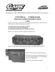
INSTALLATION INSTRUCTIONS<br />
1966-67 CHEVROLET CHEVELLE/ EL CAMINO<br />
NOTE: INSTRUCTIONS DEPICT CHEVELLE<br />
Congratulations!! You have just purchased the highest quality, best performing A/C<br />
system ever designed for you <strong>Classic</strong> Car. To obtain the high level of performance and<br />
dependability our systems are known for, pay close attention to the following<br />
instructions.<br />
Before beginning the installation check the box for the correct components.<br />
Evaporator<br />
Face Duct Assembly<br />
Defrost / Heat Duct Assembly<br />
Inlet <strong>Air</strong> Block off Assembly<br />
Firewall Block off Assembly<br />
Flex hose 2” dia. x 1ft. – 2ea.<br />
Flex hose 2” dia. x 2ft. – 1ea.<br />
Flex hose 2” dia. x 3ft. – 2ea.<br />
Sack Kit Hardware<br />
Sack Kit Control<br />
Glove box<br />
IMPORTANT INFORMATION<br />
1. Before starting, read the instructions carefully and follow proper sequence.<br />
2. Check condition of engine mounts. Excessive engine movement can damage<br />
hoses to A/C, heater, radiator, transcooler, and power steering systems.<br />
3. Before starting, check vehicle interior electrical functions. i.e. interior lights,<br />
radio, horn, etc. When ready to start installation, disconnect battery.<br />
4. Fittings. Use one or two drops of lubricant on O’rings, threads and rear of bump<br />
for O’ring where female nut rides. Do not use thread tape or sealants.<br />
5. Always use two wrenches to tighten fittings. Try holding in one hand while<br />
squeezing together while other hand holds fitting in position.<br />
6. Shaft seals in a small percentage of compressors will require as much as 3-4<br />
hours run time to become leak free.<br />
7. Compressors supplied in our complete systems are filled with proper amount of<br />
oil.<br />
8. Compressor requires technician to hand turn 15-20 revolutions before and after<br />
charging with liquid from a charging station before running system.<br />
Compressors with damaged reed valves cannot be warranted.<br />
9. Should you have any technical questions, or are suspect of missing, or defective<br />
parts, call us immediately. Our knowledgeable staff will be glad to assist you.<br />
3
YOU CAN NOW BEGIN THE INSTALLATION<br />
Remove Glove box door, glove box, discard<br />
glove box retain original hardware. Remove<br />
Radio, set aside for reinstall. Retain original<br />
hardware.<br />
Removal of Original Heater Assembly can be<br />
accomplished by disconnecting the three control<br />
cables.<br />
One attached to the Temperature door.<br />
One attached to the Heat / defrost door. This<br />
can be found behind heater box next to the<br />
throttle cable.<br />
The third cable is located on top of heater next<br />
to the defrost ducts.<br />
4
Disconnect electrical harness at the resistor<br />
block.<br />
Remove (2) screws located under the control<br />
head.<br />
Remove control head and set aside for<br />
modification and reinstall.<br />
(2) SCREWS<br />
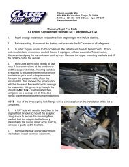
In order to remove the heater assembly, it is<br />
necessary to remove the Blower Housing<br />
Assembly first.<br />
Carefully lift vehicle and place support stands<br />
under center of the vehicle as shown.<br />
It is necessary to lower inner fender well on the passenger side. Remove the passenger<br />
front tire. Remove and retain (9) bolts from around the inner fender. Lower the inner<br />
fender well to gain access to (2) screws above and below the blower motor assembly.<br />
5
Remove (7) screws around perimeter of the<br />
Blower Housing. The (2) screws around<br />
blower motor can be accessed from below<br />
and between fender well and fender.<br />
Retain (2) screws around blower motor.<br />
Locate the <strong>Air</strong> Inlet Block Off Plate.<br />
Attach block off behind the Hood Hinge<br />
assembly. Use the original hardware.<br />
Reinstall Inner Fender Well using the<br />
original hardware. Reinstall front tire and<br />
remove the jack and stands.<br />
6
Heater hoses<br />
DRAIN COOLANT FROM RADIATOR.<br />
Remove Heater hoses from heater coil at firewall.<br />
Located behind the glove box.<br />
Remove heater assembly and discard.<br />
Locate Defrost <strong>Air</strong> Duct behind<br />
control opening in the instrument<br />
panel.<br />
Remove and retain original<br />
hardware.<br />
On page 23 of instructions is<br />
the template for the Defrost<br />
Duct. Tape in place and cut the<br />
trim line.<br />
Locate in the hardware sack kit<br />
the ¼” x ½” open cell foam.<br />
Wrap around the opening as<br />
shown.<br />
7
Locate in the hardware sack kit the Defrost duct<br />
adaptor.<br />
Attach over duct as shown using (2) #8 x ½ pan head<br />
Phillips screws.<br />
Reinstall defrost duct using original hardware.<br />
Locate behind glove box and on firewall the<br />
hole that previously mounted the heater box.<br />
Drill (1) ¾” dia. hole for the drain tube as<br />
shown.<br />
DRILL ¾” DIA. HOLE<br />
¾” BETWEEN CENTRES<br />
¾ “DIA.<br />
Above radio and in middle of the instrument panel.<br />
Cut out the opening for the center louver assembly.<br />
On page 26 of the instructions you will find a<br />
temple.<br />
Carefully ruff cut the dash using template as<br />
guide.<br />
Then go back with a file and open the hole so that<br />
louver slides through and snaps in place.<br />
8
Locate remaining templates<br />
from page 25 of<br />
instructions.<br />
Cut round holes for<br />
outboard louvers and attach<br />
the (2) ball louvers through<br />
the holes.<br />
Locate behind control opening the original wire<br />
harness.<br />
Cut off plug to the resistor.<br />
Locate wire harness that was attached to the blower<br />
switch. Cut brown wire and attach a Male Spade<br />
connector. This is power wire for the a/c unit.<br />
Cut remaining wires from the plug as far back as possible.<br />
All of the modifications to the vehicle are complete we will now begin the<br />
installation of the Unit.<br />
9
Locate Evaporator, Defrost Duct Assembly<br />
and (2) #10 x 5/8” pan head screws.<br />
Attach defrost duct to the evaporator using<br />
(2) #10 screws. Be sure that s-clips are<br />
pushed over outlet on the back side.<br />
Attach wire harness from actuator using the<br />
diagram on page 20.<br />
Locate Evaporator and defrost assembly. It is necessary to loosen the passenger side of the dash<br />
in order to slide evaporator assembly into place.<br />
Located to the right and left of the glove box<br />
opening and below the dash are (2) screws that will<br />
be removed and retained.<br />
(2) SCREWS REMOVE<br />
Locate philips head screw next to the passenger<br />
door. Remove and retain.<br />
NEXT STEP SHOWN FROM ENGINE SIDE<br />
10
UPPER MOUNTING STUD<br />
Place evaporator on floor of the vehicle. Lift<br />
unit up and behind the glove box opening. It<br />
is necessary to carefully pull the bottom of<br />
the dash to clear the evaporator.<br />
Insert upper rear Evaporator mounting stud<br />
through the original hole as shown. Attach<br />
using (1) ¼” – 20 flange nut provided.<br />
Locate in the hardware sack kit (1) ¼” –20 x 5/8”<br />
hex head screws. Attach to lower mounting<br />
bracket through the existing holes.<br />
(1) ¼”-20 X 5/8 HEX SCREW<br />
Locate in hardware sack kit the blower support<br />
brace and (2) #10 x 5/8” pan head screw. Also<br />
locate a 1/8” dia drill bit.<br />
Attach to blower motor using (1) #10 x 5/8”<br />
pan head screws. Then drill a 1/8” dia hole through<br />
brace and into the instrument panel. Attach second<br />
#10 x 5/8” pan head screw into the bottom of<br />
instrument panel.<br />
.<br />
Locate in hardware sack kit the left support<br />
brace, (1) #10 x 5/8” pan head screw and (2) #8 x<br />
3/8” pan head screws. Also locate a 1/8” dia drill<br />
bit.<br />
Using a non powered screw driver attach the<br />
brace through the holes provided on the<br />
evaporator. Carefully tighten.<br />
11
Drill a 1/8” dia. hole through brace and into the<br />
lower instrument panel.<br />
Attach brace to the panel using (1) #10 x 5/8” pan<br />
head screw.<br />
Reinstall the dash brace, and support screws.<br />
LOCATE ON UPPER<br />
MOUNTING STUD.<br />
Locate the Firewall Block Off<br />
plate, and (7) #10 x ¾” hex head<br />
tek screws.<br />
On engine side of the firewall<br />
attach over hookup tubes from<br />
the evaporator using (7) #10 x<br />
¾” hex washer head Tek screws.<br />
Locate refrigeration tape provided and seal<br />
around the hookup tubes.<br />
Locate the Water Valve and (3) worm gear<br />
clamps.<br />
Supply line from engine is attached to the upper<br />
heater hookup tube. Cut 6” off end of the<br />
RETURN LINE and install the water valve<br />
using (3) worn gear clamps as shown above.<br />
Note: It is recommended that you replace<br />
heater hoses from the engine to the hookup<br />
tubes.<br />
12
NOTE: THE NEXT FEW STEPS ARE LOCATED BEHIND THE INSTRUMENT PANEL.<br />
Locate the 2” Dia. flex hose (1) piece 12” and<br />
Cut to (2) 5” pieces. Attach to hose adaptors on<br />
top of the defrost /heat duct assembly and onto<br />
hose adaptors on the defrost duct.<br />
Locate the original control assembly. Remove and discard the following components. Retain all<br />
original hardware.<br />
(1) Original Blower Switch<br />
(2) Heat Cable<br />
(3) Temp Cable<br />
(4) <strong>Air</strong> Shutoff Cable<br />
CONNECTING<br />
WIRE<br />
BLOWER SWITCH<br />
(2) #8 X 3/8” PAN HEAD<br />
SCREW<br />
PUSH NUT<br />
Locate the control head.<br />
Locate in control sack kit the blower<br />
switch, switch connecting wire, (1) 3/16”<br />
push nut and (2) #8 x 3/8” pan head<br />
Philips screws.<br />
Slide the blower switch into position.<br />
Attach using (2) #8 x 3/8” pan head<br />
screws from underneath the control head.<br />
Hook wire through blower switch hole in<br />
the lever and then over to Control Lever.<br />
Use push nut to hold the connecting wire.<br />
13
HEAT / DEFROST<br />
CABLE<br />
FROM BACK SIDE<br />
TEMPURATURE CABLE<br />
BOTTOM LEVER<br />
Locate in control sack kit the ( SHORT) Heat / Defrost control cable, ( LONG) Temperature<br />
control cable, ( 2) 3/16” push nuts and (2) Cable Clips.<br />
Attach temperature control cable and clip to right side using the original screw and 3/16” push<br />
nut. NOTE: cable sleeve is 1/8” from the lever pin.<br />
Attach the Heat / Defrost cable to the left side. Using (1) cable clip, (1) push nut, and the original<br />
screw. NOTE: The cable sleeve IS 1/8” from lever pin.<br />
Attach Wire Harness supplied in unit to the blower switch. Reference the wiring diagram on<br />
page 20.<br />
Reinstall control head using<br />
original hardware.<br />
(2) SCREWS<br />
Route electrical assembly to Defrost Duct assembly and hookup the micro switch. Route main<br />
harness to the resistor and blower motor. Route blue clutch wire over evaporator and out through<br />
hole in firewall above the unit. Secure ground from the electronic actuator and<br />
blower motor using (2) #10 x ¾ “hex head Tek screw.<br />
14
REFER TO THE WIRING DRAWING ON PAGE 20 FOR PROPER CONNECTIONS<br />
Connect power wire (brown / from<br />
the original harness) to Red / White<br />
stripe from the new harness<br />
supplied.<br />
Insert light socket back into the control head.<br />
Route temperature cable in front and over top of the evaporator assembly and out through<br />
hole above the unit. Attach this cable to the water valve.<br />
Set control lever in the Cold position and be sure that the water valve is closed.<br />
Locate insulation tape and seal around cable at firewall.<br />
Route defrost cable and attach to the defrost / heat duct.<br />
Insert cable into first hole at the bottom.<br />
Attach using (1) #8 x 1/2” pan head Phillips screw.<br />
15
32” FLEX HOSE<br />
FACE DUCT ASSEMBLY<br />
5” FLEX HOSE<br />
Locate the face duct assembly. Attach to the evaporator outlet using s-clips at top and bottom<br />
of the duct.<br />
Locate 2“Dia. flex hose (1) piece 36 long and cut to 32” length. Attach to face duct right outlet.<br />
Route above and behind glove box opening, down to passenger ball louver.<br />
Locate 2“Dia. flex hose (1) piece 36” long. Attach to face duct left outlet. Route above and<br />
behind instrument cluster and down to the drivers ball louver.<br />
Locate 2“Dia. flex hose) piece 24” long and cut to 16” length. Attach to face duct top outlet.<br />
Route straight up and attach to center louver.<br />
Locate in hardware sack kit the Under Dash Louver with 2” oval hose adaptor. Attach it under<br />
center of Instrument Panel under controls as shown. Attach using (2)<br />
#10 x 5/8” pan head screws. Also cut 5” of 2” dia. flex hose. Attach flex hose to louver and back<br />
to front outlet on the face duct.<br />
Locate Original glove box door and the<br />
new Glove Box supplied in kit. Attach to<br />
the back side of the door using (3)<br />
#8 x 3/8” pan head screws.<br />
17
Reinstall the glove box assembly<br />
using original hardware.<br />
Caution: Carefully check under the Instrument Panel for all cables, electrical<br />
harness, or Flex Ducting that might interfere with the safe operation of the vehicle.<br />
Installation of the interior components is complete. We will now install the<br />
under hood portion of the unit.<br />
Drain and remove the radiator and fan shroud.<br />
4 th HOLE FROM TOP OF CONDENSER<br />
Locate the<br />
Condenser, (2)<br />
condenser<br />
mounting<br />
brackets, and (4)<br />
#10 x 3/8” hex<br />
head screws.<br />
Attach brackets<br />
to condenser as<br />
shown.<br />
Locate the Receiver / Drier, Drier Mounting<br />
Bracket, Aluminum Liquid tube, (2) #6 o-rings,<br />
and (2) #10 x 3/8” hex head screws.<br />
Install Receiver drier to condenser as to allow the<br />
Liquid Tube to attach as shown.<br />
Install a few drops of mineral oil to the o-ring<br />
fittings, and secure.<br />
18
Remove the battery and set aside.<br />
Carefully place Condenser<br />
Assembly through the Radiator<br />
Mounting Bulkhead as shown.<br />
Locate last (2) condenser mounting brackets<br />
and (4) #10 x 3/8” hex head screws.<br />
Attach both brackets to condenser on the<br />
engine side of bulkhead. Using (2) #10 x 3/8”<br />
hex head screws in third hole from the<br />
bottom.<br />
5/8” DIA<br />
Locate on the bulkhead above the grill, drill (1) 5/8” dia.<br />
hole in passenger side bulkhead approximately as shown.<br />
NOTE: VEHICLES EQUIPT WITH DRIVERS<br />
SIDE COMPRESSOR MOUNT.<br />
Locate on the bulkhead above the grill, drill (1)<br />
5/8” dia. hole in drivers side bulkhead<br />
approximately as shown.<br />
5/8” DIA<br />
19
NOTE: VEHICLES EQUIPT WITH PASSENGERS<br />
SIDE COMPRESSOR MOUNT.<br />
Locate on bulkhead below battery tray, drill (1) 5/8”<br />
dia. hole in the engine side of the bulkhead<br />
approximately as shown.<br />
LIQUID TUBE / DRIVERS & PASSENGER SIDE<br />
DISCHARGE TUBE /<br />
DRIVERS SIDE<br />
DISCHARGE HOSE /<br />
PASSENGER SIDE<br />
CONDENSER TUBE CONFIGURATION<br />
INSTALL THE COMPRESSOR ADAPTOR KIT AND COMPRESSOR AT<br />
THIS TIME PER THE MANUFACTURERS DIRECTIONS.<br />
NOTE: VEHICLES EQUIPT WITH PASSENGER OR DRIVERS SIDE COMPRESSOR<br />
MOUNT.<br />
Locate the fitting on the bulkhead.<br />
Locate the #8 Refrigerant Hose attach to bulkhead fitting using (1) #8 o-ring and a<br />
few drops of mineral oil.<br />
Route other end to compressor and attach using (1) #8 o-ring and a few<br />
drops of mineral oil.<br />
20
HOSE ROUTING DRIVERS SIDE<br />
HOSE ROUTING PASSENGER SIDE<br />
Locate the #10 refrigerant hose.<br />
Attach end with service fitting to the compressor using (1) #10 o-ring and a few drops of<br />
mineral oil.<br />
Attach other end to #10 fitting at the firewall. Attach using (1) #10 o-ring and a few<br />
drops of mineral oil.<br />
Tighten securely.<br />
Install HI / LOW Pressure switch into fitting<br />
from the evaporator. Tighten securely.<br />
Route (1) of the white wires along with the #8<br />
refrigerant hose. Attach to the compressor clutch.<br />
The other white wire attaches to Blue<br />
Clutch wire from the thermostat.<br />
Locate the #6 liquid hose. Attach to bulkhead<br />
fitting above the battery area. Route behind fender<br />
and up to the pressure switch assembly. Attach<br />
using (2) #6 o-ring and a few drops of mineral oil.<br />
Reinstall the battery, radiator and fan shroud using<br />
original hardware.<br />
21
THE ENGINE COMPARTMENT OF YOUR SYSTEM IS COMPLETE.<br />
THE UNIT IS READY FOR EVACUATION AND CHARGING.<br />
THIS SHOULD BE DONE BY A QUALIFIED AND CERTIFIED AIR<br />
CONDITIONING TECHNICIAN.<br />
NOTE: COMPRESSOR IS SUPPLIED WITH THE<br />
CORRECT OIL CHARGE. DO NOT ADD OIL TO SYSTEM.<br />
134A SYSTEMS 24 oz OF REFRIGERANT<br />
Recommend that power fuse is 25 amp minimum<br />
Congratulations you have completed the install of your<br />
CLASSIC AUTO AIR “Perfect Fit Series”<br />
climate control system<br />
22
IMPORTANT<br />
CAUTION: WATER VALVE MUST BE INSTALLED PER<br />
THE INSTRUCTIONS.<br />
<strong>Classic</strong> <strong>Auto</strong> <strong>Air</strong> has done extensive testing on the correct method to install the water valve in order to get a<br />
repeatable and progressive temperature control.<br />
Locate the bottom connection from the evaporator/heater unit off of the firewall and attach a 6” piece of<br />
5/8” dia. heater hose with the supplied hose clamp. Next attach the inlet side of the water valve using<br />
another supplied hose clamp, (make sure the arrow on the water valve points toward the engine) Attach a<br />
heater hose from the outlet side of the water valve and route to the connection on the water pump.<br />
NOTE: WATER VALVE = WATER PUMP<br />
FROM HEATER CORE<br />
TO WATER PUMP<br />
COOLANT FLOW<br />
CAUTION: WATER VALVE MUST BE INSTALLED ON HEATER LINE ROUTED TO<br />
WATER PUMP.<br />
NOTE: COMPRESSOR PURCHASED WITH KIT IS<br />
SUPPLIED WITH THE CORRECT OIL CHARGE. DO NOT<br />
ADD OIL TO SYSTEM.<br />
134A SYSTEMS 24 oz OF REFRIGERANT<br />
Recommend that power fuse is 25amp minimum<br />
23