LV power air circuit breakers and switch-disconnectors ... - Piti Group
LV power air circuit breakers and switch-disconnectors ... - Piti Group
LV power air circuit breakers and switch-disconnectors ... - Piti Group

You also want an ePaper? Increase the reach of your titles
YUMPU automatically turns print PDFs into web optimized ePapers that Google loves.
Performance <strong>and</strong><br />
functionality<br />
Control units<br />
Micrologic P “<strong>power</strong>”<br />
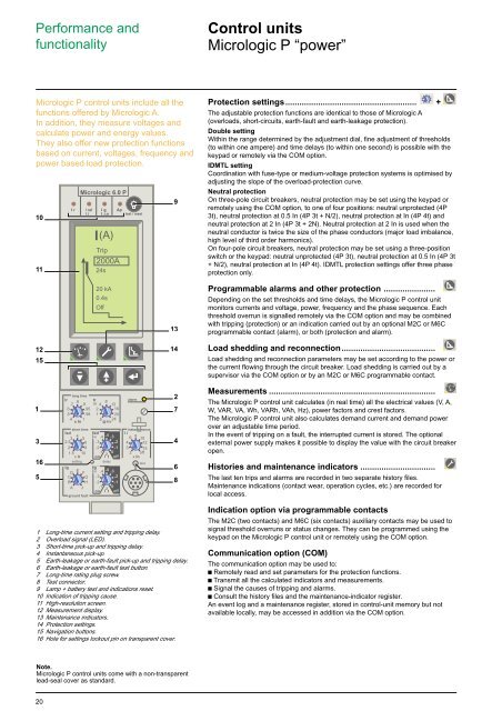
Micrologic P control units include all the<br />
functions offered by Micrologic A.<br />
In addition, they measure voltages <strong>and</strong><br />
calculate <strong>power</strong> <strong>and</strong> energy values.<br />
They also offer new protection functions<br />
based on current, voltages, frequency <strong>and</strong><br />
<strong>power</strong> based load protection.<br />
10<br />
11<br />
Micrologic 6.0 P<br />
I(A)<br />
Trip<br />
2000A<br />
24s<br />
9<br />
Protection settings........................................................ +<br />
The adjustable protection functions are identical to those of Micrologic A<br />
(overloads, short-<strong>circuit</strong>s, earth-fault <strong>and</strong> earth-leakage protection).<br />
Double setting<br />
Within the range determined by the adjustment dial, fine adjustment of thresholds<br />
(to within one ampere) <strong>and</strong> time delays (to within one second) is possible with the<br />
keypad or remotely via the COM option.<br />
IDMTL setting<br />
Coordination with fuse-type or medium-voltage protection systems is optimised by<br />
adjusting the slope of the overload-protection curve.<br />
Neutral protection<br />
On three-pole <strong>circuit</strong> <strong>breakers</strong>, neutral protection may be set using the keypad or<br />
remotely using the COM option, to one of four positions: neutral unprotected (4P<br />
3t), neutral protection at 0.5 In (4P 3t + N/2), neutral protection at In (4P 4t) <strong>and</strong><br />
neutral protection at 2 In (4P 3t + 2N). Neutral protection at 2 In is used when the<br />
neutral conductor is twice the size of the phase conductors (major load imbalance,<br />
high level of third order harmonics).<br />
On four-pole <strong>circuit</strong> <strong>breakers</strong>, neutral protection may be set using a three-position<br />
<strong>switch</strong> or the keypad: neutral unprotected (4P 3t), neutral protection at 0.5 In (4P 3t<br />
+ N/2), neutral protection at In (4P 4t). IDMTL protection settings offer three phase<br />
protection only.<br />
20 kA<br />
0.4s<br />
Off<br />
13<br />
Programmable alarms <strong>and</strong> other protection ......................<br />
Depending on the set thresholds <strong>and</strong> time delays, the Micrologic P control unit<br />
monitors currents <strong>and</strong> voltage, <strong>power</strong>, frequency <strong>and</strong> the phase sequence. Each<br />
threshold overrun is signalled remotely via the COM option <strong>and</strong> may be combined<br />
with tripping (protection) or an indication carried out by an optional M2C or M6C<br />
programmable contact (alarm), or both (protection <strong>and</strong> alarm).<br />
12 14<br />
15<br />
Load shedding <strong>and</strong> reconnection........................................<br />
Load shedding <strong>and</strong> reconnection parameters may be set according to the <strong>power</strong> or<br />
the current flowing through the <strong>circuit</strong> breaker. Load shedding is carried out by a<br />
supervisor via the COM option or by an M2C or M6C programmable contact.<br />
1<br />
3<br />
16<br />
5<br />
long time<br />
Ir<br />
.7 .8 .9<br />
.6<br />
.5<br />
.4<br />
x In<br />
.95<br />
.98<br />
1<br />
short time<br />
Isd<br />
2.5 3 4 56<br />
2 8<br />
1.5 10<br />
x Ir<br />
setting<br />
Ig<br />
D E F<br />
C<br />
B<br />
A<br />
G<br />
H<br />
J<br />
ground fault<br />
tr<br />
(s)<br />
2<br />
1<br />
.5<br />
tsd<br />
(s)<br />
4 8 12<br />
16<br />
20<br />
@ 6 Ir 24<br />
.4 .4 .3<br />
.2<br />
.3<br />
.2<br />
.1<br />
on I 2 t<br />
delay<br />
.1<br />
0<br />
off<br />
tg<br />
(s) .4 .4 .3<br />
.3 .2<br />
.2 .1<br />
.1<br />
on I 2 0<br />
t off<br />
alarm<br />
instantaneous<br />
I i<br />
6 8 10<br />
4 12<br />
3 15<br />
2 off<br />
x In<br />
test<br />
2<br />
7<br />
4<br />
6<br />
8<br />
Measurements .......................................................................<br />
The Micrologic P control unit calculates (in real time) all the electrical values (V, A,<br />
W, VAR, VA, Wh, VARh, VAh, Hz), <strong>power</strong> factors <strong>and</strong> crest factors.<br />
The Micrologic P control unit also calculates dem<strong>and</strong> current <strong>and</strong> dem<strong>and</strong> <strong>power</strong><br />
over an adjustable time period.<br />
In the event of tripping on a fault, the interrupted current is stored. The optional<br />
external <strong>power</strong> supply makes it possible to display the value with the <strong>circuit</strong> breaker<br />
open.<br />
Histories <strong>and</strong> maintenance indicators ................................<br />
The last ten trips <strong>and</strong> alarms are recorded in two separate history files.<br />
Maintenance indications (contact wear, operation cycles, etc.) are recorded for<br />
local access.<br />
1 Long-time current setting <strong>and</strong> tripping delay.<br />
2 Overload signal (LED).<br />
3 Short-time pick-up <strong>and</strong> tripping delay.<br />
4 Instantaneous pick-up.<br />
5 Earth-leakage or earth-fault pick-up <strong>and</strong> tripping delay.<br />
6 Earth-leakage or earth-fault test button.<br />
7 Long-time rating plug screw.<br />
8 Test connector.<br />
9 Lamp + battery test <strong>and</strong> indications reset.<br />
10 Indication of tripping cause.<br />
11 High-resolution screen.<br />
12 Measurement display.<br />
13 Maintenance indicators.<br />
14 Protection settings.<br />
15 Navigation buttons.<br />
16 Hole for settings lockout pin on transparent cover.<br />
Indication option via programmable contacts<br />
The M2C (two contacts) <strong>and</strong> M6C (six contacts) auxiliary contacts may be used to<br />
signal threshold overruns or status changes. They can be programmed using the<br />
keypad on the Micrologic P control unit or remotely using the COM option.<br />
Communication option (COM)<br />
The communication option may be used to:<br />
c Remotely read <strong>and</strong> set parameters for the protection functions.<br />
c Transmit all the calculated indicators <strong>and</strong> measurements.<br />
c Signal the causes of tripping <strong>and</strong> alarms.<br />
c Consult the history files <strong>and</strong> the maintenance-indicator register.<br />
An event log <strong>and</strong> a maintenance register, stored in control-unit memory but not<br />
available locally, may be accessed in addition via the COM option.<br />
Note.<br />
Micrologic P control units come with a non-transparent<br />
lead-seal cover as st<strong>and</strong>ard.<br />
20