LV power air circuit breakers and switch-disconnectors ... - Piti Group
LV power air circuit breakers and switch-disconnectors ... - Piti Group
LV power air circuit breakers and switch-disconnectors ... - Piti Group

You also want an ePaper? Increase the reach of your titles
YUMPU automatically turns print PDFs into web optimized ePapers that Google loves.
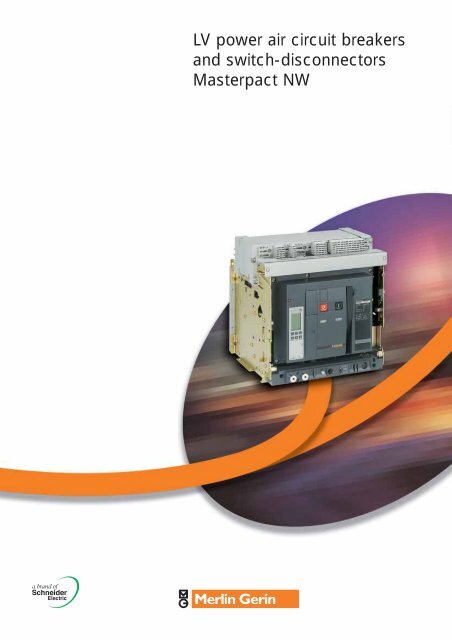
<strong>LV</strong> <strong>power</strong> <strong>air</strong> <strong>circuit</strong> <strong>breakers</strong><br />
<strong>and</strong> <strong>switch</strong>-<strong>disconnectors</strong><br />
Masterpact NW
Things<br />
never will be<br />
same<br />
the<br />
The original Masterpact has<br />
set a new st<strong>and</strong>ard for <strong>power</strong><br />
<strong>circuit</strong> <strong>breakers</strong> around the<br />
world. Over the years, other<br />
major manufacturers have<br />
tried to keep up by developing<br />
products incorporating<br />
Masterpact’s most innovative<br />
features, including the<br />
breaking principle, modular<br />
design <strong>and</strong> the use of<br />
composite materials.<br />
Today, Schneider Electric continues to<br />
innovate with the new Merlin Gerin<br />
Masterpact NW.<br />
In addition to the traditional features of<br />
<strong>power</strong> <strong>circuit</strong> <strong>breakers</strong> (withdrawability,<br />
discrimination <strong>and</strong> low maintenance),<br />
Masterpact now offers built-in<br />
communications <strong>and</strong> metering<br />
functions, all in optimised frame sizes.<br />
Masterpact NW incorporates the latest<br />
technology to enhance both<br />
performance <strong>and</strong> safety. Easy to install,<br />
with user-friendly, intuitive operation<br />
<strong>and</strong> environment-friendly design, it is,<br />
quite simply, the ultimate ACB.<br />
3
New Masterpact,<br />
new levels of performance<br />
Four performance levels<br />
H1 - for industrial sites with high short-<strong>circuit</strong> levels or installations with<br />
two parallel-connected transformers.<br />
H2 - high-performance for heavy industry where very high short-<strong>circuit</strong>s<br />
can occur.<br />
H3 - for incoming devices supplying critical applications requiring both<br />
high performance <strong>and</strong> a high level of discrimination.<br />
L1 - for high current-limiting capability <strong>and</strong> discrimination levels, as yet,<br />
unequalled by any other <strong>circuit</strong> breaker of its type. Intended for the<br />
protection of cable-type feeders or to raise the performance level of a<br />
<strong>switch</strong>board when the transformer <strong>power</strong> rating is increased.<br />
Integration in a communications<br />
network<br />
Masterpact can be integrated in a general supervision system to optimise<br />
installation operation <strong>and</strong> maintenance. The communication architecture<br />
is open, <strong>and</strong> may be upgraded for interfacing with any protocol.<br />
Switch-disconnector versions<br />
The <strong>switch</strong>-<strong>disconnectors</strong> are derived directly from the <strong>circuit</strong> <strong>breakers</strong><br />
<strong>and</strong> offer the same features <strong>and</strong> performance levels.<br />
1000 V <strong>and</strong> 400 Hz<br />
distribution systems<br />
The Masterpact range<br />
can be used on 1000V<br />
installations (mining<br />
industry) <strong>and</strong> 400Hz<br />
systems (aeronautics,<br />
computer centres).<br />
4
2 frame sizes, one family<br />
Masterpact NW<br />
800 to 4000A<br />
4000 to 6300A<br />
5
Optimised<br />
volumes<br />
Practical installation<br />
solutions<br />
The new range improves upon all the<br />
installation solutions which have already made<br />
Masterpact a success. It has been designed to<br />
st<strong>and</strong>ardise <strong>switch</strong>boards, optimise volumes<br />
<strong>and</strong> simplify installation:<br />
■ Incoming connection to top or bottom<br />
terminals.<br />
■ No safety clearance required.<br />
■ Connection:<br />
■ Horizontal or vertical rear connection.<br />
■ Front connection with minimum extra space.<br />
■ Mixed front <strong>and</strong> rear connections.<br />
■ 115 mm pole pitch on all versions.<br />
■ No derating up to 55° C <strong>and</strong> 4000A.<br />
Optimised volumes<br />
Up to 4000A, Masterpact NW <strong>circuit</strong> <strong>breakers</strong><br />
are all the same size, the same size as the<br />
previous M32 frame.<br />
From 4000A to 6300A, there is just one size,<br />
which is considerably smaller than before.<br />
Retrofit solutions<br />
Special connections are available to replace a<br />
fixed or drawout Masterpact M08 to M32 with a<br />
Masterpact NW, without modifying the busbars<br />
6
Ease of<br />
installation<br />
With optimised sizes, the Masterpact NW range<br />
simplifies the design of <strong>switch</strong>boards <strong>and</strong> selection/<br />
installation of devices:<br />
■ Three connection layouts for Masterpact NW:<br />
■ One from 800 to 3200A (NW08 - NW32).<br />
■ One for 4000 A (NW40a).<br />
■ One 4000 to 6300A (NW40b - NW63).<br />
■ Identical auxiliary connection terminals from 800<br />
to 6300A (Masterpact NW).<br />
■ Front connections do not impact on the depth<br />
of the device.<br />
■ Rear connections are converted from<br />
vertical or horizontal busbars, simply by<br />
turning the connectors through 90°.<br />
Connection to busbars.<br />
Vertical front connection of a fixed Masterpact NW.<br />
Vertical <strong>and</strong> horizontal rear connection<br />
of a fixed Masterpact NW.<br />
7
Innovation<br />
Greater dependability…<br />
Filtered breaking<br />
The patented new design of the arc chutes includes stainless-steel filters.<br />
The chutes absorb the energy released during breaking, thus limiting the<br />
stresses exerted on the installation. They filter <strong>and</strong> cool the gases<br />
produced, reducing the external effects of short <strong>circuit</strong> clearance.<br />
Automatic unlatching(H3 <strong>and</strong> L1)<br />
The automatic unlatching of the <strong>circuit</strong> breaker operating mechanism for<br />
high short-<strong>circuit</strong>s extends performance up to 150kA. It produces ultrafast<br />
tripping for all short-<strong>circuit</strong>s higher than 37 kA (L1) <strong>and</strong> 65 kA (H3).<br />
For lower short-<strong>circuit</strong>s, the system does not react so that the control unit<br />
can provide total discrimination with downstream devices.<br />
Filtered breaking<br />
More intelligent trip units…<br />
Today, with the high speed of calculation, the small size of memory <strong>and</strong><br />
advances in miniaturisation, trip units have become <strong>circuit</strong> breaker control<br />
units offering increasingly <strong>power</strong>ful functions. They accurately measure<br />
system parameters, instantly calculate values, store data, log events,<br />
signal alarms, communicate, take action, etc. The new Masterpact range<br />
equipped with Micrologic control units, constitute both an extremely<br />
reliable protective device <strong>and</strong> an accurate measurement instrument.<br />
User friendly…<br />
Intuitive use…<br />
Micrologic control units are equipped with a digital LCD display used in<br />
conjunction with simple navigation buttons. Users can directly access<br />
parameters <strong>and</strong> settings. Navigation between screens is intuitive <strong>and</strong> the<br />
immediate display of values greatly simplifies settings. Text is displayed in<br />
the desired language.<br />
Navigation buttons on a Micrologic P<br />
control unit.<br />
… backed by incomparable security<br />
Protection functions are separate from the measurement functions <strong>and</strong><br />
are managed by an ASIC electronic component. This independence<br />
guarantees immunity from conducted or radiated disturbances <strong>and</strong><br />
ensures a high degree of reliability.<br />
A patented “double setting” system for protection functions establishes:<br />
■ A maximum threshold set using the control-unit dials.<br />
■ Fine adjustments via the keypad or remotely.<br />
The fine adjustments for thresholds (to within one ampere) <strong>and</strong> tripping<br />
delays (to within a fraction of a second) are displayed directly on the<br />
screen.<br />
The control unit cover can be lead-sealed to prevent uncontrolled access<br />
to the dials <strong>and</strong> protect the settings.<br />
8
Ready for<br />
the future<br />
Compliance with<br />
environmental<br />
requirements<br />
Schneider Electric fully take into account<br />
environmental requirements, starting right from<br />
the design phase of every product, through to<br />
the end of its service life:<br />
■ The materials used for Masterpact are not<br />
dangerous to the environment.<br />
■<br />
■<br />
■<br />
■<br />
The production facilities are non-polluting in<br />
compliance with the ISO 14001 st<strong>and</strong>ard.<br />
Filtered breaking eliminates pollution in the<br />
<strong>switch</strong>board.<br />
The energy dissipated per pole is low,<br />
making energy losses insignificant.<br />
The materials are marked to facilitate sorting<br />
for recycling at the end of product service<br />
life.<br />
Simple upgrading of<br />
installations<br />
Installations changes <strong>and</strong> <strong>power</strong> level increases<br />
normally mean new equipment <strong>and</strong><br />
<strong>switch</strong>boards extensions:<br />
■ All control units are interchangeable.<br />
■<br />
■<br />
Communication with a supervision system is<br />
an option that may be added at any time.<br />
A reserve chassis can be pre-addressed so<br />
that system parameters do not have to be<br />
modified when a drawout device is installed<br />
at a later date.<br />
9
Masterpact NW<br />
Performance & functionality<br />
Product panorama 3<br />
General overview<br />
Detailed contents 12<br />
Circuit <strong>breakers</strong> <strong>and</strong> <strong>switch</strong>-<strong>disconnectors</strong><br />
NW08 to NW63 14<br />
Micrologic control units<br />
Overview of functions 16<br />
Micrologic A «ammeter» 18<br />
Micrologic P «<strong>power</strong> meter» 20<br />
Micrologic H «harmonics» 24<br />
Accessories <strong>and</strong> test equipment 26<br />
Communication<br />
Architecture 28<br />
Indicate, control, set, etc. 29<br />
Connections<br />
Overview of solutions 30<br />
Optional accessories 31<br />
Locking<br />
On the device 32<br />
On the chassis 33<br />
Indication contacts 34<br />
Remote operation<br />
Remote ON/OFF 36<br />
Remote tripping 39<br />
Accessories 40<br />
Source-changeover systems<br />
Presentation 41<br />
Mechanical interlocking 42<br />
Electrical interlocking 43<br />
Associated automatic controllers 44<br />
Dimensions <strong>and</strong> connection details 45<br />
Electrical diagrams 65<br />
Installation recommendations 73<br />
Protection characteristics 91<br />
11
menu<br />
long time<br />
Ir<br />
.7 .8 tr<br />
alarm<br />
.9 (s) 4 8 12<br />
.6 .95 2 16<br />
.5 .98 1 20<br />
.4 1 .5<br />
x In<br />
short time<br />
instantaneous<br />
Isd<br />
tsd<br />
I i<br />
(s) .4 .4 .3<br />
2.5 3 4 10<br />
56 .3 .2 4<br />
2 8 .2 .1 3 15<br />
1.5 10 .1<br />
on I 2 0 2 off<br />
x Ir<br />
t off x In<br />
setting<br />
delay<br />
test<br />
Ig<br />
D E tg<br />
F .4 .4 .3<br />
C G .3 .2<br />
B H .2 .1<br />
A J .1<br />
I 2 0<br />
t off<br />
ground fault<br />
Performance <strong>and</strong><br />
functionality<br />
General overview<br />
Detailed contents<br />
This chapter describes all the functions<br />
offered by Masterpact NW devices.<br />
Circuit <strong>breakers</strong> <strong>and</strong> <strong>switch</strong>-<strong>disconnectors</strong> page 14<br />
■ Ratings:<br />
■ Masterpact NW 800 to 6300 A.<br />
■ Circuit <strong>breakers</strong> type H1, H2, H3, L1.<br />
■ Switch-<strong>disconnectors</strong> type HA, HF.<br />
■ 3 or 4 poles.<br />
■ Fixed or drawout versions.<br />
■ Option with neutral on the right.<br />
■ Protection derating.<br />
Micrologic control units page 16<br />
Ammeter A<br />
5.0 selective protection<br />
6.0 selective + earth-fault protection<br />
7.0 selective + earth-leakage protection<br />
Micrologic 6.0 A<br />
Micrologic 6.0 P<br />
Power meter P<br />
5.0 selective protection<br />
6.0 selective + earth-fault protection<br />
100 %<br />
7.0 selective + earth-leakage protection<br />
Harmonic meter H*<br />
5.0 selective protection<br />
6.0 selective + earth-fault protection<br />
7.0 selective + earth-leakage protection<br />
■ External sensor for earth-fault protection.<br />
■ Rectangular sensor for earth-leakage protection.<br />
■ Setting options (long-time rating plug):<br />
■ Low setting 0.4 to 0.8 x Ir.<br />
■ High setting 0.8 to 1 x Ir.<br />
■ Without long-time protection.<br />
■ External <strong>power</strong>-supply module.<br />
■ Battery module.<br />
Communication page 28<br />
■ Modbus + batibus<br />
Connections page 30<br />
■ Rear connection (horizontal or vertical).<br />
■ Front connection.<br />
■ Mixed connections.<br />
■ Optional accessories.<br />
■ Interphase barriers.<br />
■ Disconnectable front-connection adapter.<br />
■ Shutter position indication <strong>and</strong> locking.<br />
40 %<br />
(s)<br />
on<br />
@ 6 Ir 24<br />
6 8 12<br />
(s)<br />
on<br />
@ 6 Ir 24<br />
6 8 12<br />
* Availability to be announced<br />
12
Performance <strong>and</strong><br />
functionality<br />
Locking page 32<br />
■ Pushbutton locking by padlockable transparent cover.<br />
■ OFF-position locking by padlock or keylock.<br />
■ Chassis locking in disconnected position by keylock.<br />
■ Chassis locking in connected, disconnected<br />
<strong>and</strong> test positions.<br />
■ Door interlock (inhibits door opening with breaker<br />
in connected position).<br />
■ Racking interlock (inhibits racking with door open).<br />
■ Racking interlock between crank <strong>and</strong> OFF pushbutton.<br />
■ Automatic spring discharge before breaker removal.<br />
■ Mismatch protection.<br />
Indication contacts page 34<br />
■ St<strong>and</strong>ard or low-level contacts:<br />
■ ON/OFF indication (OF).<br />
■ «fault trip» indication (SDE).<br />
■ Carriage <strong>switch</strong>es for connected (CE),<br />
disconnected (CD) <strong>and</strong> test (CT) positions.<br />
■ Programmable contacts:<br />
■ 2 contacts (M2C).<br />
■ 6 contacts (M6C).<br />
M2C contact<br />
OF contact<br />
Remote operation page 36<br />
■ Remote ON/OFF:<br />
■ Gear motor.<br />
■ XF closing or MX opening voltage releases.<br />
■ PF ready-to-close contact.<br />
■ Options: RAR automatic or Res electrical<br />
remote reset:<br />
- BPFE electrical closing pushbutton.<br />
■ Remote tripping function:<br />
■ MN voltage release:<br />
- St<strong>and</strong>ard.<br />
Gear motor<br />
- Adjustable or non-adjustable delay.<br />
■ Or second MX voltage release.<br />
MX, XF <strong>and</strong> MN voltage<br />
releases<br />
Accessories page 40<br />
■ Auxiliary terminal shield.<br />
■ Operation counter.<br />
■ Escutcheon.<br />
■ Transparent cover for escutcheon.<br />
■ Escutcheon blanking plate.<br />
00399<br />
13
Performance <strong>and</strong><br />
functionality<br />
Circuit <strong>breakers</strong><br />
<strong>and</strong> <strong>switch</strong>-<strong>disconnectors</strong><br />
NW08 to NW63<br />
Common characteristics<br />
Number of poles 3 / 4<br />
Rated insulation voltage (V) Ui 1000/1250<br />
Impulse withst<strong>and</strong> voltage (kV) Uimp 12<br />
Rated operational voltage (V AC 50/60 Hz) Ue 690/1150<br />
Suitability for isolation BSEN 60947-2<br />
Degree of pollution IEC 60664-1 4<br />
Circuit-breaker characteristics as per BSEN 60947-2<br />
Rated current (A) In at 40°C/**50°C<br />
Rating of 4th pole (A)<br />
Sensor ratings (A)<br />
Type of <strong>circuit</strong> breaker<br />
Ultimate breaking capacity (kA rms) Icu 220/415 V<br />
V AC 50/60 Hz<br />
440 V<br />
525 V<br />
690 V<br />
1150 V<br />
Rated service breaking capacity (kA rms) Ics % Icu<br />
Rated short-time withst<strong>and</strong> current (kA rms) Icw 1s<br />
V AC 50/60 Hz<br />
3s<br />
Electrodynamic withst<strong>and</strong> (kA peak)<br />
Iintegrated instantaneous protection (kA peak ± 10%)<br />
Rated making capacity (kA peak) Icm 220/415 V<br />
V AC 50/60 Hz<br />
440 V<br />
525 V<br />
690 V<br />
1150 V<br />
Break time (ms)<br />
Closing time (ms)<br />
Circuit-breaker characteristics as per NEMA AB1<br />
Breaking capacity (kA)<br />
V AC 50/60 Hz<br />
240 V<br />
480 V<br />
600 V<br />
Switch-disconnector characteristics as per BSEN 60947-3<br />
Type of <strong>switch</strong>-disconnector<br />
Rated making capacity (kA peak) Icm 220/415 V<br />
V AC 50/60 Hz<br />
440 V<br />
500/690 V<br />
1150 V<br />
Rated short-time withst<strong>and</strong> current (kA rms) Icw 1 s<br />
V AC 50/60 Hz<br />
3 s<br />
Ultimate breaking capacity (Icu) with external protection relay,<br />
Maximum delay 350 ms<br />
Installation, connection <strong>and</strong> maintenance<br />
Service life Mechanical with maintenance<br />
C/O cycles x 1000<br />
without maintenance<br />
Electrical without maintenance 440 V<br />
690 V<br />
1150 V<br />
Motor control (AC3-947-4)<br />
690 V<br />
Connection drawout FC<br />
RC<br />
fixed FC<br />
RC<br />
Dimensions (mm) drawout 3P<br />
H x W x D<br />
4P<br />
fixed 3P<br />
4P<br />
Weight (kg) drawout 3P/4P<br />
(approximate) fixed 3P/4P<br />
* See the current-limiting curve in the «additional characteristics» section.<br />
(1) except 4000 A.<br />
** 50°C for rear vertically connected.<br />
14
Performance <strong>and</strong><br />
functionality<br />
NW08 NW10 NW12 NW16 NW20 NW25 NW32 NW40 NW40b NW50 NW63<br />
800 1000 1250 1600 2000 2500 3200 4000 4000 5000 6300<br />
800 1000 1250 1600 2000 2500 3200 4000 4000 5000 6300<br />
400 400 630 800 1000 1250 1600 2000 2000 2500 3200<br />
to 800 to 1000 to 1250 to 1600 to 2000 to 2500 to 3200 to 4000 to 4000 to 5000 to 6300<br />
H1 H2 L1* H10 H1 H2 H3 L1* H10 H1 H2 H3 H10 H1 H2<br />
65 100 150 - 65 100 150 150 - 65 100 150 - 100 150<br />
65 100 150 - 65 100 150 150 - 65 100 150 - 100 150<br />
65 85 130 - 65 85 130 130 - 65 85 130 - 100 130<br />
65 85 100 - 65 85 100 100 - 65 85 100 - 100 100<br />
- - - 50 - - - - 50 - - - 50 - -<br />
100 % 100 % 100 % 100 %<br />
65 85 30 50 65 85 65 30 50 65 85 65 50 100 100<br />
36 50 30 50 36 50 65 30 50 36 50 65 50 100 100<br />
143 187 90 105 143 187 190 90 105 143 187 190 105 220 220<br />
without 190 80 without without 190 150 80 without without 190 150 without without270<br />
143 220 330 - 143 220 330 330 - 143 220 330 - 220 330<br />
143 220 330 - 143 220 330 330 - 143 220 330 - 220 330<br />
143 187 286 - 143 187 286 286 - 143 187 286 - 220 286<br />
143 187 220 - 143 187 220 220 - 143 187 220 - 220 220<br />
- - - 105 - - - - 105 - - - 105 - -<br />
25 25 10 25 25 25 25 10 25 25 25 25 25 25 25<br />
< 70 < 70 < 70 < 80<br />
65 100 150 - 65 100 150 150 - 65 100 150 - 100 150<br />
65 100 150 - 65 100 150 150 - 65 100 150 - 100 150<br />
65 85 100 - 65 85 100 100 - 65 85 100 - 100 100<br />
HA HF HA10 HA HF HA10 HA HF HA10 HA<br />
105 187 - 105 187 - 121 187 - 187<br />
105 187 - 105 187 - 121 187 - 187<br />
105 187 - 105 187 - 121 187 - 187<br />
- - 105 - - 105 - - 105 -<br />
50 85 50 50 85 50 55 85 50 85<br />
36 75 50 36 75 50 55 75 50 85<br />
50 85 50 50 85 50 55 85 50 85<br />
25 20 20 10<br />
12.5 10 10 5<br />
10 10 3 - 8 8 2 3 - 5 5 1.25 - 1.5 1.5<br />
10 10 3 - 6 6 2 3 - 2.5 2.5 1.25 - 1.5 1.5<br />
- - - 0.5 - - - - 0.5 - - - 0.5 - -<br />
10 10 - - 6 6 6 - - 2.5 2.5 2.5 - - -<br />
c c c c c c c c c c c c c - -<br />
c c c c c c c c c c c c c c c<br />
c c - - c c - - - c (1) c (1) - - - -<br />
c c - - c c - - - c c - - c c<br />
439 x 441 x 395 479 x 786 x 395<br />
439 x 556 x 395 479 x 1016 x 395<br />
352 x 422x 297 352 x 767x 297<br />
352 x 537x 297 352 x 997x 297<br />
90/120 225/300<br />
60/80 120/160<br />
Sensor selection<br />
Sensor rating (A) 400 630 800 1000 1250 1600 2000 2500 3200 4000 5000 6300<br />
Ir threshold 160 250 320 400 500 630 800 1000 1250 1600 2000 2500<br />
setting (A) to 400 to 630 to 800 to 1000 to 1250 to 1600 to 2000 to 2500 to 3200 to 4000 to 5000 to 6300<br />
15
Performance <strong>and</strong><br />
functionality<br />
Micrologic control units<br />
Overview of functions<br />
All Masterpact <strong>circuit</strong> <strong>breakers</strong> can be<br />
equipped with a Micrologic control unit.<br />
Control units are designed to protect Power<br />
<strong>circuit</strong>s <strong>and</strong> loads. Alarms may be<br />
programmed for remote indications.<br />
Measurements of current, voltage,<br />
frequency, <strong>power</strong> <strong>and</strong> <strong>power</strong> quality<br />
optimise continuity of service <strong>and</strong> energy<br />
management.<br />
Dependability<br />
The use of an ASIC electronic component for protection functions in all Micrologic<br />
control units, guarantees a high degree of reliability <strong>and</strong> immunity to conducted or<br />
radiated disturbances.<br />
On Micrologic A, P <strong>and</strong> H* control units, advanced functions are managed by an<br />
independent microprocessor.<br />
Micrologic name codes<br />
5.0 A<br />
X Y Z<br />
t<br />
Micrologic 5: selective protection<br />
X: type of protection<br />
c 5 for selective protection.<br />
c 6 for selective + earth-fault protection.<br />
c 7 for selective + earth-leakage protection.<br />
Y: control-unit generation<br />
Identification of the control-unit generation.<br />
“0” signifies the first generation.<br />
Z: type of measurement<br />
c A for “ammeter”.<br />
c P for “<strong>power</strong> meter”.<br />
0 Ir Isd Ii I<br />
t<br />
Protection:<br />
long time + short time + instantaneous<br />
Micrologic 6: selective + earth-fault protection<br />
t<br />
0 Ir Isd Ii I<br />
0 Ig<br />
I<br />
Protection:<br />
long time<br />
+ short time<br />
+ instantaneous<br />
+ earth fault<br />
Micrologic 7: selective + earth-leakage protection<br />
t<br />
t<br />
0 Ir Isd Ii I<br />
0 I∆n I<br />
Protection:<br />
long time<br />
+ short time<br />
+ instantaneous<br />
+ earth leakage<br />
* Availability to be announced<br />
16
menu<br />
long time<br />
Ir<br />
.7 .8 tr<br />
alarm<br />
.9 4 8 12<br />
.6 .95 2 16<br />
.5 .98 1 20<br />
.4 1 .5<br />
x In<br />
short time<br />
instantaneous<br />
Isd<br />
tsd<br />
I i<br />
(s) .4 .4 .3<br />
2.5 3 4 10<br />
56 .3 .2 4<br />
2 8 .2 .1 3 15<br />
1.5 10 .1<br />
on I 2 0 2 off<br />
x Ir<br />
t off x In<br />
setting<br />
delay<br />
test<br />
.4<br />
menu<br />
menu<br />
off<br />
long time<br />
Ir<br />
.7 .8 tr<br />
alarm<br />
.9 (s) 4 8 12<br />
.6 .95 2 16<br />
.5 .98 1 20<br />
.4 1 .5<br />
x In<br />
short time<br />
instantaneous<br />
Isd<br />
tsd<br />
I i<br />
(s) .4 .4 .3<br />
2.5 3 4 10<br />
56 .3 .2 4<br />
2 8 .2 .1 3 15<br />
1.5 10 .1<br />
on I 2 0 2 off<br />
x Ir<br />
t off x In<br />
setting<br />
delay<br />
test<br />
Ig<br />
D E tg<br />
(s)<br />
F .4 .4 .3<br />
C G .3 .2<br />
B H .2 .1<br />
A J .1<br />
on I 2 0<br />
t off<br />
ground fault<br />
long time<br />
Ir<br />
.7 .8 tr<br />
alarm<br />
.9 4 8 12<br />
.6 .95 2 16<br />
.5 .98 1 20<br />
.4 1 .5<br />
x In<br />
short time<br />
instantaneous<br />
Isd<br />
tsd<br />
I i<br />
(s) .4 .4 .3<br />
2.5 3 4 10<br />
56 .3 .2 4<br />
2 8 .2 .1 3 15<br />
1.5 10 .1<br />
on I 2 0 2 off<br />
x Ir<br />
t off<br />
setting<br />
delay<br />
test<br />
long time<br />
Ir<br />
.7 .8 tr<br />
alarm<br />
.9 (s) 4 8 12<br />
.6 .95 2 16<br />
.5 .98 1 20<br />
.4 1 .5<br />
x In<br />
short time<br />
instantaneous<br />
Isd<br />
tsd<br />
I i<br />
(s) .4 .4 .3<br />
2.5 3 4 10<br />
56 .3 .2 4<br />
2 8 .2 .1 3 15<br />
1.5 10 .1<br />
on I 2 0 2 off<br />
x Ir<br />
t off x In<br />
setting<br />
delay<br />
test<br />
Ig<br />
D E tg<br />
(s)<br />
F .4 .4 .3<br />
C G .3 .2<br />
B H .2 .1<br />
A J .1<br />
on I 2 0<br />
t off<br />
ground fault<br />
long time<br />
Ir<br />
.7 .8 tr<br />
alarm<br />
.9 (s) 4 8 12<br />
.6 .95 2 16<br />
.5 .98 1 20<br />
.4 1 .5<br />
x In<br />
short time<br />
instantaneous<br />
Isd<br />
tsd<br />
I i<br />
(s) .4 .4 .3<br />
2.5 3 4 10<br />
56 .3 .2 4<br />
2 8 .2 .1 3 15<br />
1.5 10 .1<br />
on I 2 0 2 off<br />
x Ir<br />
t off x In<br />
setting<br />
delay<br />
test<br />
Ig<br />
D E tg<br />
F .4 .4 .3<br />
C G .3 .2<br />
B H .2 .1<br />
A J .1<br />
I 2 0<br />
t off<br />
ground fault<br />
long time<br />
Ir<br />
.7 .8 tr<br />
alarm<br />
.9 (s) 4 8 12<br />
.6 .95 2 16<br />
.5 .98 1 20<br />
.4 1 .5<br />
x In<br />
short time<br />
instantaneous<br />
Isd<br />
tsd<br />
I i<br />
(s) .4 .4 .3<br />
2.5 3 4 10<br />
56 .3 .2 4<br />
2 8 .2 .1 3 15<br />
1.5 10 .1<br />
on I 2 0 2 off<br />
x Ir<br />
t off x In<br />
setting<br />
delay<br />
test<br />
Ig<br />
D E tg<br />
F .4 .4 .3<br />
C G .3 .2<br />
B H .2 .1<br />
A J .1<br />
I 2 0<br />
t off<br />
ground fault<br />
long time<br />
Ir<br />
.7 .8 tr<br />
alarm<br />
.9 (s) 4 8 12<br />
.6 .95 2 16<br />
.5 .98 1 20<br />
.4 1 .5<br />
x In<br />
short time<br />
instantaneous<br />
Isd<br />
tsd<br />
I i<br />
(s) .4 .4 .3<br />
2.5 3 4 10<br />
56 .3 .2 4<br />
2 8 .2 .1 3 15<br />
1.5 10 .1<br />
on I 2 0 2 off<br />
x Ir<br />
t off x In<br />
setting<br />
delay<br />
test<br />
Ig<br />
D E tg<br />
F .4 .4 .3<br />
C G .3 .2<br />
B H .2 .1<br />
A J .1<br />
I 2 0<br />
t off<br />
ground fault<br />
Performance <strong>and</strong><br />
functionality<br />
Measurements <strong>and</strong> programmable protection<br />
A: ammeter<br />
■ I1, I2, I3, IN, Iearth-fault, Iearth-leakage measurement <strong>and</strong> display<br />
■ Fault indications.<br />
■ Settings in amperes <strong>and</strong> in seconds.<br />
P: A + <strong>power</strong> meter + programmable protection<br />
■ Measurements of V, A, W, VAR, VA, Wh, VARh, VAh, Hz, Vpeak, Apeak, <strong>power</strong> factor <strong>and</strong> max<br />
<strong>and</strong> min readings.<br />
■ IDMTL long-time protection, minimum <strong>and</strong> maximum voltage <strong>and</strong> frequency, voltage <strong>and</strong><br />
current imbalance, phase sequence, reverse <strong>power</strong>.<br />
■ Load shedding <strong>and</strong> reconnection depending on <strong>power</strong> or current.<br />
■ Measurements of interrupted currents, differentiated fault indications, maintenance<br />
indications, event histories <strong>and</strong> time-stamping, etc.<br />
H: P + harmonics<br />
■ Power quality: fundamentals, distortion, amplitude <strong>and</strong> phase of harmonics up to the 51st<br />
order.<br />
■ Waveform capture after fault, alarm or open request.<br />
■ Enhanced alarm programming: thresholds <strong>and</strong> actions.<br />
5.0 A<br />
Micrologic 6.0 A<br />
5.0 P<br />
Micrologic 6.0 P<br />
5.0 H*<br />
Micrologic 6.0 P<br />
100 %<br />
40 %<br />
(s) @ 6 Ir 24<br />
@ 6 Ir 24<br />
6 8 12<br />
(s)<br />
@ 6 Ir 24 x In<br />
6 8 12<br />
6 8 12<br />
6.0 A<br />
Micrologic 6.0 A<br />
6.0 P<br />
Micrologic 6.0 P<br />
6.0 H*<br />
Micrologic 6.0 P<br />
100 %<br />
40 %<br />
@ 6 Ir 24<br />
@ 6 Ir 24<br />
@ 6 Ir 24<br />
6 8 12<br />
6 8 12<br />
(s)<br />
on<br />
6 8 12<br />
7.0 A<br />
Micrologic 6.0 A<br />
7.0 P<br />
Micrologic 6.0 P<br />
7.0 H*<br />
Micrologic 6.0 P<br />
100 %<br />
40 %<br />
@ 6 Ir 24<br />
@ 6 Ir 24<br />
@ 6 Ir 24<br />
6 8 12<br />
(s)<br />
on<br />
6 8 12<br />
(s)<br />
on<br />
6 8 12<br />
* Available June 2002<br />
17
Performance <strong>and</strong><br />
functionality<br />
Control units<br />
Micrologic A “ammeter”<br />
In addition to <strong>power</strong> <strong>circuit</strong> protection,<br />
micrologic A control units offer:<br />
Measurements, display, communication<br />
<strong>and</strong> current maximeters. Version 6<br />
provides earth-fault protection, version 7<br />
provides earth-leakage protection.<br />
10<br />
100 %<br />
Micrologic 6.0 A<br />
∆t= I∆n=<br />
tsd= tr=<br />
Isd=<br />
Ii= Ir=<br />
Ig=<br />
tg=<br />
40 %<br />
menu<br />
MAX<br />
kA s<br />
9<br />
11<br />
12<br />
13<br />
Protection settings........................................................<br />
Protection thresholds <strong>and</strong> delays are set using the adjustment dials, with<br />
the selected values momentarily displayed in amperes <strong>and</strong> in seconds.<br />
Setting accuracy may be enhanced by limiting the setting range using a different<br />
long-time rating plug (0.8 to 1 x In).<br />
Overload protection<br />
True rms long-time protection.<br />
Thermal memory: thermal image before <strong>and</strong> after tripping.<br />
Short-<strong>circuit</strong> protection<br />
Short-time (rms) <strong>and</strong> instantaneous protection.<br />
Selection of I 2 t type (ON or OFF) for short-time delay.<br />
Earth fault protection<br />
Unrestricted earth fault(restricted on request).<br />
Selection of I 2 t type (ON or OFF) for delay.<br />
Residual earth-leakage protection (Vigi).<br />
Operation without an external <strong>power</strong> supply.<br />
d Protected against nuisance tripping.<br />
k DC-component withst<strong>and</strong> class A up to 10 A.<br />
Neutral protection<br />
On four-pole <strong>circuit</strong> <strong>breakers</strong>, neutral protection may be set using a three-position<br />
<strong>switch</strong>: neutral unprotected (4P 3t), neutral protection at 0.5 In (4P 3t + N/2),<br />
neutral protection at 100% In (4P 4t).<br />
For 3 Pole devices please refer to Micrologic P.<br />
Zone selective interlocking (ZSI)<br />
A ZSI terminal block may be used to interconnect a number of control units to<br />
provide total discrimination for short-time <strong>and</strong> earth-fault protection, without a delay<br />
before tripping.<br />
menu<br />
“Ammeter” measurements...........................................<br />
Micrologic A control units measure the true rms value of currents.<br />
A digital LCD screen continuously displays the most heavily loaded phase (Imax)<br />
or displays the I1, I2, I3, IN, Ig, I∆n, stored interrupted current (maximeter) <strong>and</strong> setting<br />
values by scrolling through with the navigation button.<br />
1<br />
3<br />
5<br />
long time<br />
Ir<br />
.7 .8 .9<br />
.6<br />
.5<br />
.4<br />
x In<br />
.95<br />
.98<br />
1<br />
short time<br />
Isd<br />
2.5 3 4 56<br />
2 8<br />
1.5 10<br />
x Ir<br />
setting<br />
Ig<br />
D E F<br />
C<br />
B<br />
A<br />
G<br />
H<br />
J<br />
ground fault<br />
tr<br />
(s)<br />
2<br />
1<br />
.5<br />
tsd<br />
(s)<br />
4 8 12<br />
16<br />
20<br />
@ 6 Ir 24<br />
.4 .4 .3<br />
.2<br />
.3<br />
.2<br />
.1<br />
on I 2 t<br />
delay<br />
.1<br />
0<br />
off<br />
tg<br />
(s) .4 .4 .3<br />
.3 .2<br />
.2 .1<br />
.1<br />
on I 2 0<br />
t off<br />
alarm<br />
instantaneous<br />
I i<br />
6 8 10<br />
4 12<br />
3 15<br />
2 off<br />
x In<br />
test<br />
2<br />
7<br />
4<br />
6<br />
8<br />
Communication option<br />
In conjunction with the COM communication option, the control unit transmits the<br />
following:<br />
c Setting values.<br />
c All “ammeter” measurements.<br />
c Tripping causes.<br />
c Maximeter reset.<br />
1 Long-time current setting <strong>and</strong> tripping delay.<br />
2 Overload signal (LED).<br />
3 Short-time pick-up <strong>and</strong> tripping delay.<br />
4 Instantaneous pick-up.<br />
5 Earth-leakage or earth-fault pick-up <strong>and</strong> tripping delay.<br />
6 Earth-leakage or earth-fault test button.<br />
7 Long-time rating plug screw.<br />
8 Test connector.<br />
9 Lamp test, reset <strong>and</strong> battery test.<br />
10 Indication of tripping cause.<br />
11 Digital display.<br />
12 Three-phase bargraph <strong>and</strong> ammeter.<br />
13 Navigation buttons.<br />
Note.<br />
Micrologic A control units come with a transparent leadseal<br />
cover as st<strong>and</strong>ard.<br />
18
Performance <strong>and</strong><br />
functionality<br />
Protection<br />
Micrologic 2.0 A<br />
Long time<br />
Current setting (A) Ir = In x … 0.4 0.5 0.6 0.7 0.8 0.9 0.95 0.98 1<br />
Tripping between 1.05 <strong>and</strong> 1.20 x Ir<br />
other ranges or disable by changing rating plug<br />
Time delay (s) tr at 1.5 x Ir 12.5 25 50 100 200 300 400 500 600<br />
Accuracy: 0 to -20 % tr at 6 x Ir 0.5 1 2 4 8 12 16 20 24<br />
tr ay 7.2 x Ir 0.34 0.69 1.38 2.7 5.5 8.3 11 13.8 16.6<br />
Thermal memory<br />
20 minutes before <strong>and</strong> after tripping<br />
Instantaneous<br />
Pick-up (A) Isd = Ir x … 1.5 2 2.5 3 4 5 6 8 10<br />
Accuracy: ±10 %<br />
Time delay<br />
fixed: 20 ms<br />
Ammeter<br />
Micrologic 2.0 A<br />
Continuous current measurements<br />
Measurements from 20 to 200 % of In I1 I2 I3 IN<br />
Accuracy: 1.5% (including sensors)*<br />
Maximeters I1 max I2 max I3 max IN max<br />
Protection<br />
Micrologic 5.0 / 6.0 / 7.0 A<br />
Long time<br />
Micrologic 5.0 / 6.0 / 7.0 A<br />
Current setting (A) Ir = In x … 0.4 0.5 0.6 0.7 0.8 0.9 0.95 0.98 1<br />
Tripping between 1.05 <strong>and</strong> 1.20 x Ir<br />
other ranges or disable by changing rating plug<br />
Time delay (s) tr at 1.5 x Ir 12.5 25 50 100 200 300 400 500 600<br />
Accuracy: 0 to -20 % tr at 6 x Ir 0.5 1 2 4 8 12 16 20 24<br />
tr at 7.2 x Ir 0.34 0.69 1.38 2.7 5.5 8.3 11 13.8 16.6<br />
Thermal memory<br />
20 minutes before <strong>and</strong> after tripping<br />
Short time<br />
Pick-up (A) Isd = Ir x … 1.5 2 2.5 3 4 5 6 8 10<br />
Accuracy: ±10 %<br />
Time delay (ms) at 10 Ir settings I 2 t Off 0 0.1 0.2 0.3 0.4<br />
I 2 t On 0.1 0.2 0.3 0.4<br />
tsd (max resettable time) 20 80 140 230 350<br />
tsd (max break time) 80 140 200 320 500<br />
Instantaneous<br />
Pick-up (A) Ii = In x … 2 3 4 6 8 10 12 15 off<br />
Accuracy: ±10 %<br />
Earth fault<br />
Micrologic 6.0 A<br />
Pick up (A) Ig = In x … A B C D E F G H J<br />
Accuracy: ±10 % In i 400 A 0.3 0.3 0.4 0.5 0.6 0.7 0.8 0.9 1<br />
400 A < In i 1200 A 0.2 0.3 0.4 0.5 0.6 0.7 0.8 0.9 1<br />
In > 1200 A 500 640 720 800 880 960 1040 1120 1200<br />
Time delay (ms) settings I 2 t Off 0 0.1 0.2 0.3 0.4<br />
at In or 1200 A I 2 t On 0.1 0.2 0.3 0.4<br />
tg (max resettable time) 20 80 140 230 350<br />
tg (max break time) 80 140 200 320 500<br />
Residual earth leakage (Vigi)<br />
Micrologic 7.0 A<br />
Sensitivity (A) I∆n 0.5 1 2 3 5 7 10 20 30<br />
Accuracy: 0 to -20 %<br />
Time delay (ms.) settings 60 140 230 350 800<br />
t∆n (max resettable time) 80 140 230 350 800<br />
t∆n (max break time) 140 200 320 500 1000<br />
Ammeter<br />
Micrologic 5.0 / 6.0 / 7.0 A<br />
Continuous current measurements<br />
Measurements from 20 to 200 % of In I1 I2 I3 IN Ig I∆n<br />
Accuract: 1.5 % (including sensors)*<br />
Maximeters I1 max I2 max I3 max IN max Ig max I∆n max<br />
t<br />
Ir<br />
tr<br />
Isd<br />
0 I<br />
t<br />
Ir<br />
menu<br />
tr<br />
Isd<br />
tsd<br />
Ii<br />
0 I<br />
t<br />
I 2 t on<br />
Ig<br />
I 2 t off<br />
tg<br />
0 I<br />
t<br />
I∆n<br />
t∆n<br />
0 I<br />
menu<br />
Note.<br />
All current-based protection functions require no additional <strong>power</strong> source.<br />
The reset button resets alarms, maximeters <strong>and</strong> stored interrupted-current indications.<br />
* Ammeter display is lost when current falls below 20% of In.<br />
19
Performance <strong>and</strong><br />
functionality<br />
Control units<br />
Micrologic P “<strong>power</strong>”<br />
Micrologic P control units include all the<br />
functions offered by Micrologic A.<br />
In addition, they measure voltages <strong>and</strong><br />
calculate <strong>power</strong> <strong>and</strong> energy values.<br />
They also offer new protection functions<br />
based on current, voltages, frequency <strong>and</strong><br />
<strong>power</strong> based load protection.<br />
10<br />
11<br />
Micrologic 6.0 P<br />
I(A)<br />
Trip<br />
2000A<br />
24s<br />
9<br />
Protection settings........................................................ +<br />
The adjustable protection functions are identical to those of Micrologic A<br />
(overloads, short-<strong>circuit</strong>s, earth-fault <strong>and</strong> earth-leakage protection).<br />
Double setting<br />
Within the range determined by the adjustment dial, fine adjustment of thresholds<br />
(to within one ampere) <strong>and</strong> time delays (to within one second) is possible with the<br />
keypad or remotely via the COM option.<br />
IDMTL setting<br />
Coordination with fuse-type or medium-voltage protection systems is optimised by<br />
adjusting the slope of the overload-protection curve.<br />
Neutral protection<br />
On three-pole <strong>circuit</strong> <strong>breakers</strong>, neutral protection may be set using the keypad or<br />
remotely using the COM option, to one of four positions: neutral unprotected (4P<br />
3t), neutral protection at 0.5 In (4P 3t + N/2), neutral protection at In (4P 4t) <strong>and</strong><br />
neutral protection at 2 In (4P 3t + 2N). Neutral protection at 2 In is used when the<br />
neutral conductor is twice the size of the phase conductors (major load imbalance,<br />
high level of third order harmonics).<br />
On four-pole <strong>circuit</strong> <strong>breakers</strong>, neutral protection may be set using a three-position<br />
<strong>switch</strong> or the keypad: neutral unprotected (4P 3t), neutral protection at 0.5 In (4P 3t<br />
+ N/2), neutral protection at In (4P 4t). IDMTL protection settings offer three phase<br />
protection only.<br />
20 kA<br />
0.4s<br />
Off<br />
13<br />
Programmable alarms <strong>and</strong> other protection ......................<br />
Depending on the set thresholds <strong>and</strong> time delays, the Micrologic P control unit<br />
monitors currents <strong>and</strong> voltage, <strong>power</strong>, frequency <strong>and</strong> the phase sequence. Each<br />
threshold overrun is signalled remotely via the COM option <strong>and</strong> may be combined<br />
with tripping (protection) or an indication carried out by an optional M2C or M6C<br />
programmable contact (alarm), or both (protection <strong>and</strong> alarm).<br />
12 14<br />
15<br />
Load shedding <strong>and</strong> reconnection........................................<br />
Load shedding <strong>and</strong> reconnection parameters may be set according to the <strong>power</strong> or<br />
the current flowing through the <strong>circuit</strong> breaker. Load shedding is carried out by a<br />
supervisor via the COM option or by an M2C or M6C programmable contact.<br />
1<br />
3<br />
16<br />
5<br />
long time<br />
Ir<br />
.7 .8 .9<br />
.6<br />
.5<br />
.4<br />
x In<br />
.95<br />
.98<br />
1<br />
short time<br />
Isd<br />
2.5 3 4 56<br />
2 8<br />
1.5 10<br />
x Ir<br />
setting<br />
Ig<br />
D E F<br />
C<br />
B<br />
A<br />
G<br />
H<br />
J<br />
ground fault<br />
tr<br />
(s)<br />
2<br />
1<br />
.5<br />
tsd<br />
(s)<br />
4 8 12<br />
16<br />
20<br />
@ 6 Ir 24<br />
.4 .4 .3<br />
.2<br />
.3<br />
.2<br />
.1<br />
on I 2 t<br />
delay<br />
.1<br />
0<br />
off<br />
tg<br />
(s) .4 .4 .3<br />
.3 .2<br />
.2 .1<br />
.1<br />
on I 2 0<br />
t off<br />
alarm<br />
instantaneous<br />
I i<br />
6 8 10<br />
4 12<br />
3 15<br />
2 off<br />
x In<br />
test<br />
2<br />
7<br />
4<br />
6<br />
8<br />
Measurements .......................................................................<br />
The Micrologic P control unit calculates (in real time) all the electrical values (V, A,<br />
W, VAR, VA, Wh, VARh, VAh, Hz), <strong>power</strong> factors <strong>and</strong> crest factors.<br />
The Micrologic P control unit also calculates dem<strong>and</strong> current <strong>and</strong> dem<strong>and</strong> <strong>power</strong><br />
over an adjustable time period.<br />
In the event of tripping on a fault, the interrupted current is stored. The optional<br />
external <strong>power</strong> supply makes it possible to display the value with the <strong>circuit</strong> breaker<br />
open.<br />
Histories <strong>and</strong> maintenance indicators ................................<br />
The last ten trips <strong>and</strong> alarms are recorded in two separate history files.<br />
Maintenance indications (contact wear, operation cycles, etc.) are recorded for<br />
local access.<br />
1 Long-time current setting <strong>and</strong> tripping delay.<br />
2 Overload signal (LED).<br />
3 Short-time pick-up <strong>and</strong> tripping delay.<br />
4 Instantaneous pick-up.<br />
5 Earth-leakage or earth-fault pick-up <strong>and</strong> tripping delay.<br />
6 Earth-leakage or earth-fault test button.<br />
7 Long-time rating plug screw.<br />
8 Test connector.<br />
9 Lamp + battery test <strong>and</strong> indications reset.<br />
10 Indication of tripping cause.<br />
11 High-resolution screen.<br />
12 Measurement display.<br />
13 Maintenance indicators.<br />
14 Protection settings.<br />
15 Navigation buttons.<br />
16 Hole for settings lockout pin on transparent cover.<br />
Indication option via programmable contacts<br />
The M2C (two contacts) <strong>and</strong> M6C (six contacts) auxiliary contacts may be used to<br />
signal threshold overruns or status changes. They can be programmed using the<br />
keypad on the Micrologic P control unit or remotely using the COM option.<br />
Communication option (COM)<br />
The communication option may be used to:<br />
c Remotely read <strong>and</strong> set parameters for the protection functions.<br />
c Transmit all the calculated indicators <strong>and</strong> measurements.<br />
c Signal the causes of tripping <strong>and</strong> alarms.<br />
c Consult the history files <strong>and</strong> the maintenance-indicator register.<br />
An event log <strong>and</strong> a maintenance register, stored in control-unit memory but not<br />
available locally, may be accessed in addition via the COM option.<br />
Note.<br />
Micrologic P control units come with a non-transparent<br />
lead-seal cover as st<strong>and</strong>ard.<br />
20
Performance <strong>and</strong><br />
functionality<br />
Protection Micrologic 5.0 / 6.0 / 7.0 P +<br />
Long time (rms)<br />
Micrologic 5.0 / 6.0 / 7.0 P<br />
Current setting (A) Ir = In x … 0.4 0.5 0.6 0.7 0.8 0.9 0.95 0.98 1<br />
Tripping between 1.05 <strong>and</strong> 1.20 x Ir<br />
other ranges or disable by changing rating plug<br />
Time delay (s) tr at 1.5 x Ir 12.5 25 50 100 200 300 400 500 600<br />
Accuracy: 0 to -20 % tr at 6 x Ir 0.5 1 2 4 8 12 16 20 24<br />
tr at 7.2 x Ir 0.34 0.69 1.38 2.7 5.5 8.3 11 13.8 16.6<br />
IDMTL setting curve slope SIT VIT EIT HVFuse DT<br />
Thermal memory<br />
20 minutes before <strong>and</strong> after tripping<br />
Short time (rms)<br />
Pick-up (A) Isd = Ir x … 1.5 2 2.5 3 4 5 6 8 10<br />
Accuracy: ±10 %<br />
Time delay (ms.) at 10 x Ir settings I 2 t Off 0 0.1 0.2 0.3 0.4<br />
I 2 t On 0.1 0.2 0.3 0.4<br />
tsd (max resettable time) 20 80 140 230 350<br />
tsd (max break time) 80 140 200 320 500<br />
Instantaneous<br />
Pick-up (A) Ii = In x … 2 3 4 6 8 10 12 15 OFF<br />
Accuracy: ±10 %<br />
Earth fault<br />
Micrologic 6.0 P<br />
Pick-up (A) Ig = In x … A B C D E F G H J<br />
Accuracy: ±10 % In i 400 A 0.3 0.3 0.4 0.5 0.6 0.7 0.8 0.9 1<br />
400 A < In i 1200 A 0.2 0.3 0.4 0.5 0.6 0.7 0.8 0.9 1<br />
In > 1200 A 500 640 720 800 880 960 1040 1120 1200<br />
Time delay (ms.) at 10 x Ir settings I 2 t Off 0 0.1 0.2 0.3 0.4<br />
I 2 t On 0.1 0.2 0.3 0.4<br />
tg (max resettable time) 20 80 140 230 350<br />
tg (max break time) 80 140 200 320 500<br />
Residual earth leakage (Vigi)<br />
Micrologic 7.0 P<br />
Sensitivity (A) I∆n 0.5 1 2 3 5 7 10 20 30<br />
Accuracy: 0 to -20 %<br />
Time delay (ms.) settings 60 140 230 350 800<br />
t∆n (max resettable time) 60 140 230 350 800<br />
t∆n (max break time) 140 200 320 500 1000<br />
t<br />
0<br />
t<br />
0 I<br />
t<br />
Ir<br />
IDMTL<br />
Ig<br />
I∆n<br />
tr<br />
tg<br />
Isd<br />
tsd<br />
t∆n<br />
I 2 t on<br />
I 2 t off<br />
0 I<br />
Ii<br />
I<br />
Alarms <strong>and</strong> other protection<br />
Micrologic 5.0 / 6.0 / 7.0 P<br />
Current threshold time delay<br />
Current imbalance Iimbalance 0.05 to 0.6 Imax 1 to 40 s.<br />
Maximum dem<strong>and</strong> current Imax dem<strong>and</strong>: I1, I2, I3, IN, Ig 0.4 In at short-time pick-up 0 to 1500 s.<br />
Voltage<br />
Voltage imbalance Uimbalance 0.02 to 0.3 Uaverage 1 to 40 s.<br />
Minimum voltage Umin 60 to 690 V between phases 0.2 to 5 s.<br />
Maximum voltage Umax 100 to 930 V between phases 0.2 to 5 s.<br />
Power<br />
Reverse <strong>power</strong> rP 5 to 500 kW 0.2 to 20 s.<br />
Frequency<br />
Minimum frequency Fmin 45 to 400 Hz 0.2 to 5 s.<br />
Maximum frequency Fmax 45 to 540 Hz 0.2 to 5 s.<br />
Phase sequence<br />
Sequence ∆Ø Ø1/2/3 or Ø1/3/2 instantaneous<br />
t<br />
threshold<br />
threshold<br />
delay<br />
delay<br />
0 I/U/P/F<br />
Load shedding <strong>and</strong> reconnection<br />
Micrologic 5.0 / 6.0 / 7.0 P<br />
Measured value threshold time delay<br />
Current I 0.5 to 1 Ir per phases 20% tr to 80% tr.<br />
Power P 200 kW to 10 MW 10 to 3600 s.<br />
t<br />
threshold<br />
threshold<br />
delay<br />
delay<br />
0 I/P<br />
Note.<br />
All current-based protection functions require no additional <strong>power</strong> supplies .<br />
Voltage-based protection functions are connected to AC <strong>power</strong> via a voltage<br />
measurement input built into the <strong>circuit</strong> breaker.<br />
21
Performance <strong>and</strong><br />
functionality<br />
Control units<br />
Micrologic P “<strong>power</strong>”<br />
3850A<br />
N<br />
100<br />
50<br />
0<br />
U 12 =<br />
U 23 =<br />
U 31 =<br />
U 1N =<br />
U 2N =<br />
U 3N =<br />
1 2 3<br />
Default display<br />
Uinst.<br />
F (Hz)<br />
60.0<br />
Trip<br />
history<br />
400V<br />
404V<br />
401V<br />
230V<br />
229V<br />
233V<br />
Display of a voltage<br />
Display of a frequency<br />
Ir<br />
03/08/1999<br />
Isd<br />
27/07/1999<br />
Umax<br />
30/06/1999<br />
Display of a tripping history<br />
I 1 = 4800A<br />
I 2 = 4600A<br />
I 3 = 4000A<br />
I N = 200A<br />
I = 13A<br />
P<br />
Q<br />
S<br />
Pdem<strong>and</strong><br />
Pdem<strong>and</strong>e<br />
PActive P (kW)<br />
2180 kW +2180<br />
Q<br />
Réactive<br />
(kVAR)<br />
Q<br />
- 650 kVAR -650<br />
S (kVA)<br />
Apparente +2280 S<br />
2280 kVA<br />
Trip<br />
03/08/1999<br />
12:02:36<br />
Ir =<br />
I 1 =<br />
I 2 =<br />
I 3 =<br />
Imax<br />
instant.<br />
Reset ( + / - )<br />
Display of a maximum<br />
current<br />
I N =<br />
Pinst.<br />
(kW)<br />
+2180<br />
(kVAR)<br />
-650<br />
(kVA)<br />
+2280<br />
Display of a <strong>power</strong><br />
Display of a dem<strong>and</strong> <strong>power</strong><br />
1000A<br />
1200A<br />
1430A<br />
1060A<br />
53A<br />
Display after tripping<br />
Navigation from one display to another is intuitive. The six buttons on the keypad<br />
provide access to the menus <strong>and</strong> easy selection of values. When the setting cover<br />
is closed, the keypad may no longer be used to access the protection settings, but<br />
still provides access to the displays for measurements, histories, indicators, etc.<br />
Measurements .......................................................................<br />
Instantaneous values<br />
The value displayed on the screen is refreshed every second.<br />
Minimum <strong>and</strong> maximum values of measurements are stored in the memory<br />
(minimeters <strong>and</strong> maximeters).<br />
Currents<br />
I rms A 1 2 3 N<br />
A e-fault e-leakage<br />
I max rms A 1 2 3 N<br />
A e-fault e-leakage<br />
Voltages<br />
U rms V 12 23 31<br />
V rms V 1N 2N 3N<br />
U average rms V (U12 + U23 + U31) / 3<br />
U imbalance %<br />
Power, energy<br />
P active, Q reactive, S apparent W, Var, VA totals<br />
E active, E reactive, E apparent Wh, VARh, VAh totals consumed - supplied<br />
totals consumed<br />
totals supplied<br />
Power factory PF total<br />
Frequencies<br />
F<br />
Hz<br />
Dem<strong>and</strong> metering<br />
The dem<strong>and</strong> is calculated over a fixed or sliding time window that may be<br />
programmed from 5 to 60 minutes. According to the contract signed with the <strong>power</strong><br />
supplier, an indicator associated with a load shedding function makes it possible to<br />
avoid or minimise the costs of overrunning the subscribed <strong>power</strong>. Maximum<br />
dem<strong>and</strong> values are systematically stored <strong>and</strong> time stamped (maximeter).<br />
Currents<br />
I dem<strong>and</strong> A 1 2 3 N<br />
A e-fault e-leakage<br />
I max dem<strong>and</strong> A 1 2 3 N<br />
A e-fault e-leakage<br />
Power<br />
P, Q, S dem<strong>and</strong> W, Var, VA totals<br />
P, Q, S max dem<strong>and</strong> W, Var, VA totals<br />
Minimeters <strong>and</strong> maximeters<br />
Only the current <strong>and</strong> <strong>power</strong> maximeters may be displayed on the screen.<br />
Histories .................................................................................<br />
The last ten trips <strong>and</strong> alarms are recorded in two separate history files that may be<br />
displayed on the screen.<br />
c Tripping history:<br />
v Type of fault.<br />
v Date <strong>and</strong> time.<br />
v Values measured at the time of tripping (interrupted current, etc.).<br />
c Alarm history:<br />
v Type of fault.<br />
v Date <strong>and</strong> time.<br />
v Values measured at the time of the alarm.<br />
Maintenance indicators ........................................................<br />
A number of maintenance indicators may be called up on the screen:<br />
c Contact wear.<br />
c Operation counter:<br />
v Cumulative total.<br />
v Total since last reset.<br />
22
Performance <strong>and</strong><br />
functionality<br />
Schneider PowerLogic software. Event Log display<br />
With the communication option additional measurements,<br />
maximeters <strong>and</strong> minimeters are available<br />
The following measured or calculated values are only accessible with the COM<br />
communication option:<br />
c I peak / r, (I1 + I2 + I3)/3, I imbalance.<br />
c Load level in % Ir.<br />
c Total <strong>power</strong> factor.<br />
The maximeters <strong>and</strong> minimeters are available only via the COM option for use with<br />
a supervisor.<br />
Event log<br />
All events are time stamped.<br />
c Trips.<br />
c Beginning <strong>and</strong> end of alarms.<br />
c Modifications to settings <strong>and</strong> parameters.<br />
c Counter reset.<br />
c System faults:<br />
v Fallback position.<br />
v Thermal self-protection.<br />
c Loss of time.<br />
c Overrun of wear indicators.<br />
c Test-kit connections.<br />
Maintenance register<br />
Used as an aid in troubleshooting <strong>and</strong> to plan for device maintenance operations.<br />
c Highest current measured.<br />
c Operation counter.<br />
c Number of test-kit connections.<br />
c Number of trips in operating mode <strong>and</strong> in test mode.<br />
c Contact-wear indicator.<br />
Additional technical characteristics<br />
Setting the display language<br />
System messages may be displayed in six different languages. The desired language is<br />
selected via the keypad.<br />
Protection functions<br />
All current-based protection functions require no auxiliary source. Voltage-based<br />
protection functions are connected to AC <strong>power</strong> via a voltage measurement input built<br />
into the <strong>circuit</strong> breaker.<br />
Measurement functions<br />
Measurement functions are independent of the protection functions.<br />
The high-accuracy measurement module operates independently of the protection<br />
module, while remaining synchronised with protection events.<br />
Measurement-calculation mode<br />
c Measurement functions are based on the new “zero blind time” concept which<br />
continuously measures signals at a high sampling rate, rather than the traditional<br />
“blind window” process. This method ensures accurate energy calculations even for<br />
highly variable loads (welding machines, robots, etc.).<br />
c Energies are calculated on the basis of the instantaneous <strong>power</strong> values, in two ways:<br />
v The traditional mode where only positive (consumed) energies are considered<br />
v The signed mode where the positive (consumed) <strong>and</strong> negative (supplied) energies<br />
are considered separately.<br />
Accuracy of measurements (including sensors)<br />
c Voltage (V) 1%.<br />
c Current (A) 1.5%.<br />
c Frequency (Hz) 0.1 Hz.<br />
c Power (W) <strong>and</strong> energy (Wh) 2.5%.<br />
Stored information<br />
The fine setting adjustments, the last 100 events <strong>and</strong> the maintenance register remain in<br />
the control-unit memory even when <strong>power</strong> is lost.<br />
Time-stamping<br />
Time-stamping is activated only if an external <strong>power</strong> supply module is present (max. drift<br />
of 1 hour per year).<br />
Reset<br />
An individual reset, via the keypad or via COM, acts on alarms, minimum <strong>and</strong> maximum<br />
data, peak values, the counters <strong>and</strong> indicators.<br />
23
Performance <strong>and</strong><br />
functionality<br />
Control units<br />
Micrologic H “harmonics”<br />
Micrologic H control units include all the<br />
functions offered by Micrologic P.<br />
Integrating significantly enhanced<br />
calculation <strong>and</strong> memory functions, the<br />
Micrologic H control unit offers in-depth<br />
analysis of <strong>power</strong> quality <strong>and</strong> detailed<br />
event diagnostics.<br />
long time<br />
Ir<br />
.7 .8 .9<br />
.6<br />
.5<br />
.4<br />
I<br />
x In<br />
Micrologic 7.0 H<br />
U<br />
P<br />
E<br />
.95<br />
.98<br />
1<br />
tr<br />
(s)<br />
4 8 12<br />
16<br />
20<br />
2<br />
1<br />
.5<br />
@ 6 Ir 24<br />
(A)<br />
(V)<br />
(kW)<br />
(kWh)<br />
Harmonics<br />
earth leakage<br />
alarm<br />
short time<br />
instantaneous<br />
Isd<br />
tsd<br />
I i<br />
(s) .4 .4 .3<br />
2.5 3 4 6 56<br />
8 10<br />
.3 .2 4 12<br />
2 8 .2 .1 3 15<br />
1.5 10 .1<br />
on I 2 0 2 off<br />
x Ir<br />
t off x In<br />
setting<br />
delay<br />
test<br />
I∆n ∆t<br />
(A)<br />
3 5 (ms)<br />
7 230 350<br />
2 10<br />
140<br />
1 20<br />
.5 30 60 800<br />
In addition to the Micrologic P functions, the Micrologic H control unit offers:<br />
c In-depth analysis of <strong>power</strong> quality including calculation of harmonics <strong>and</strong> the<br />
fundamentals.<br />
c Diagnostics aid <strong>and</strong> event analysis through waveform capture.<br />
c Enhanced alarm programming to analyse <strong>and</strong> track down a disturbance on the<br />
AC <strong>power</strong> system.<br />
Measurements .......................................................................<br />
The Micrologic H* control unit offers all the measurements carried out by Micrologic<br />
P, with the addition of:<br />
c Phase by phase measurements of:<br />
v Power, energy.<br />
v Power factors.<br />
c Calculation of:<br />
v Current <strong>and</strong> voltage total harmonic distortion (THD).<br />
v Current, voltage <strong>and</strong> <strong>power</strong> fundamentals (50 Hz).<br />
v Current <strong>and</strong> voltage harmonics up to the 51st order.<br />
Instantaneous values displayed on the screen.<br />
Currents<br />
I rms A 1 2 3 N<br />
A e-fault e-leakage<br />
I max rms A 1 2 3 N<br />
A e-fault e-leakage<br />
Voltages<br />
U rms V 12 23 31<br />
V rms V 1N 2N 3N<br />
U average rms V (U12 + U23 + U31) / 3<br />
U imbalance %<br />
Power, energy<br />
P active, Q reactive, S apparent W, Var, VA totals 1 2 3<br />
E active, E reactive, E apparent Wh, VARh, VAh totals consumed - supplied<br />
totals consumed<br />
totals supplied<br />
Power factor PF total 1 2 3<br />
Frequencies<br />
F<br />
Hz<br />
Power-quality indicators<br />
Total fundamentals U I P Q S<br />
THD % U I<br />
U <strong>and</strong> I harmonics amplitude 3 5 7 9 11 13<br />
Harmonics 3, 5, 7, 9, 11 <strong>and</strong> 13, monitored by electrical utilities, are displayed on the<br />
screen.<br />
Dem<strong>and</strong> measurements<br />
Similar to the Micrologic P control unit, the dem<strong>and</strong> values are calculated over a<br />
fixed or sliding time window that may be set from 5 to 60 minutes.<br />
Currents<br />
I dem<strong>and</strong> A 1 2 3 N<br />
A e-fault e-leakage<br />
I max dem<strong>and</strong> A 1 2 3 N<br />
A e-fault e-leakage<br />
Power<br />
P, Q, S dem<strong>and</strong> W, Var, VA totals<br />
P, Q, S max dem<strong>and</strong> W, Var, VA totals<br />
Maximeters<br />
Only the current maximeters may be displayed on the screen.<br />
Histories <strong>and</strong> maintenance indicators<br />
These functions are identical to those of the Micrologic P.<br />
Note.<br />
Micrologic H control units come with a non-transparent<br />
lead-seal cover as st<strong>and</strong>ard.<br />
24
Performance <strong>and</strong><br />
functionality<br />
POWERLOGIC System Manager Demo<br />
File Edit View Setup Control Display Tools<br />
Reports Window Help<br />
Time<br />
% Fundamental<br />
Ready<br />
1,20<br />
1,00<br />
0,80<br />
0,60<br />
0,40<br />
0,20<br />
0,00<br />
POWERLOGIC System Manager Demo<br />
File Edit View Setup Control Display Tools<br />
Reports Window Help<br />
167<br />
83<br />
0<br />
-83<br />
-167<br />
167<br />
83<br />
0<br />
-83<br />
-167<br />
Event<br />
Phase A-N Voltage<br />
17 33 50 66<br />
Phase B-N Voltage<br />
17 33 50<br />
Sampling Mode : MANUAL<br />
Phase A-N Voltage - Harmonics Analysis<br />
Sampling Mode : MANUAL<br />
642<br />
321<br />
0<br />
-321<br />
5 seconds<br />
Phase A Current<br />
17 33 50<br />
Your Specific Device - Phase A-N Voltage<br />
-642<br />
Fundamental: 118.08<br />
RMS: 118.11<br />
RMS-H: 2.38<br />
Peak: 166.86<br />
CF: 1.41<br />
THD: 2.02<br />
OK<br />
5 seconds<br />
Module<br />
H2 H3 H4 H5 H6 H7 H8 H9 H10 H11 H12<br />
Harmonics<br />
Display of harmonics up to 12th order.<br />
Fundamental:<br />
RMS:<br />
RMS-H:<br />
Peak:<br />
CF:<br />
THD:<br />
Phase 1-N<br />
Harmonics(RMS)<br />
H1: 118.09<br />
H2: 0.01<br />
H3: 0.45<br />
H4: 0.03<br />
H5: 0.45<br />
H6: 0.04<br />
H7: 1.27<br />
H8: 0.05<br />
H9: 0.42<br />
H10: 0.01<br />
H11: 1.03<br />
H12: 0.07<br />
ONLINE: DEMO No working system 9:30<br />
OK<br />
Harmonics(RMS)<br />
H1: 118.09<br />
H2: 0.01<br />
H3: 0.45<br />
H4: 0.03<br />
H5: 0.45<br />
H6: 0.04<br />
H7: 1.27<br />
H8: 0.05<br />
H9: 0.42<br />
H10: 0.01<br />
H11: 1.03<br />
H12: 0.07<br />
66<br />
With the communication option additional measurements,<br />
maximeters <strong>and</strong> minimeters are available<br />
The following measured or calculated values are only accessible with the COM<br />
communication option:<br />
c I peak / r, (I1 + I2 + I3)/3, I imbalance<br />
c Load level in % Ir.<br />
c Power factor (total <strong>and</strong> per phase).<br />
c Voltage <strong>and</strong> current THD.<br />
c K factors of currents <strong>and</strong> average K factor.<br />
c Crest factors of currents <strong>and</strong> voltages.<br />
c All fundamentals per phase.<br />
c Fundamental current <strong>and</strong> voltage phase displacement.<br />
c Distortion <strong>power</strong> <strong>and</strong> distortion factor, phase by phase.<br />
c Amplitude <strong>and</strong> displacement of current <strong>and</strong> voltage harmonics 3 to 51.<br />
The maximeters <strong>and</strong> minimeters are available only via the COM option for use with<br />
a supervisory system.<br />
Waveform capture<br />
The Micrologic H control unit stores the last 12 cycles of each instantaneous<br />
current or voltage measurement. On request or automatically on programmed<br />
events, the control unit stores the waveforms. The waveforms may be displayed in<br />
the form of oscillograms by a supervisory system via the COM option.<br />
Enhanced alarm programming<br />
Each instantaneous value can be compared to user-set, high <strong>and</strong> low threshold<br />
overrun to generate an alarm. An alarm or combinations of alarms can be linked to<br />
programmable actions, including <strong>circuit</strong>-breaker opening, activation of a M2C or<br />
M6C contact, selective recording of measurements in a log <strong>and</strong> waveform capture.<br />
Event log <strong>and</strong> maintenance registers<br />
The Micrologic H offers the same event log <strong>and</strong> maintenance register functions as<br />
the Micrologic P.<br />
Ready<br />
ONLINE: DEMO No working system 9:30<br />
Waveform capture<br />
POWERLOGIC System Manager Demo<br />
File Edit View Setup Control Display Tools<br />
Reports Window Help<br />
Time<br />
Ready<br />
Log<br />
Event<br />
Sampling Mode : MANUAL<br />
5 seconds<br />
Module<br />
04/21/98 08:49:06 Net Server Shutdown User : master Level : 1 PowerLogic Network…<br />
04/21/98 08:49:01 User Log Out User : master User level : 1 SMS-3000 Client<br />
04/21/98 08:48:38 DB Table Change User : master TOD Event Tasks Alarm Setup<br />
04/21/98 08:48:30 DB Table Change User : master Tasks Alarm Setup<br />
04/21/98 08:46:16 DB Table Change User : master TOD Events Alarm Setup<br />
04/21/98 08:39:19 User Log In User : master User level : 1 SMS-3000 Client<br />
04/21/98 08:39:06 Security Check Key Status : Key Found PowerLogic Network…<br />
04/21/98 08:39:06 Net Server Started User : master Level : 1 PowerLogic Network…<br />
04/21/98 08:38:57 User Log In Event/Alarm/Network…<br />
04/21/98 08:30:44 Net Server Shutdown User : master Level : 1 PowerLogic Network…<br />
04/21/98 08:24:31 Security Check Key Status : Key Found PowerLogic Network…<br />
04/21/98 08:24:30 Net server Started User : master Level : 1 PowerLogic Network…<br />
04/21/98 08:24:15 User Log IN Event/Alarm/Network…<br />
04/21/98 08:18:07 IPC Error User : NA Err : 109 SMS-3000 Client<br />
04/21/98 07:54:05 DB Table Change User : -1 Logger Template Devices Logger Setup<br />
04/21/98 07:53:55 DB Table Change User : -1 Logger Template Topics Logger Setup<br />
04/21/98 07:53:54 DB Table Change User : -1 Logger Templates Logger Setup<br />
04/21/98 07:51:46 DB Table Change User : master Analog Levels Assigned Alarm Setup<br />
04/21/98 07:51:33 DB Table Change User : master Analog Levels Template Alarm Setup<br />
04/21/98 07:51:29 DB Table Change User : master Functions Alarm Setup<br />
04/21/98 07:50:17 DB Table Change User : master Digital Levels Assigned Alarm Setup<br />
04/21/98 07:50:17 DB Table Change User : master Analog Levels Assigned Alarm Setup<br />
04/21/98 07:49:13 Setup: Device Name Device : MicroLogic User :master Device Setup<br />
Change Breaker<br />
04/21/98 07:48:57 Setup: Device Added Device : MicroLogic Breaker User :master Device Setup<br />
04/21/98 07:48:38 Setup: Device Name Change Device : Transformer Temp User : master Device Setup<br />
04/21/98 07:48:22 Setup: Device Added Device : Transformer Temp User :master Device Setup<br />
04/21/98 07:46:54 User Log In User : master User Level : 1 SMS-3000 Client<br />
04/21/98 07:44:59 Security Check Key Status : Key Found PowerLogic Network…<br />
04/21/98 07:44:59 Net Server Started User :master Level : 1 PowerLogic Network…<br />
ONLINE: DEMO No working system 9:30<br />
Additional technical characteristics<br />
Setting the display language<br />
System messages may be displayed in six different languages. The desired language is<br />
selected via the keypad.<br />
Protection functions<br />
All current-based protection functions require no auxiliary source. Voltage-based<br />
protection functions are connected to AC <strong>power</strong> via a voltage measurement input built<br />
into the <strong>circuit</strong> breaker.<br />
Measurement functions<br />
Measurement functions are independent of the protection functions.<br />
The high-accuracy measurement module operates independently of the protection<br />
module, while remaining synchronised with protection events.<br />
Measurement-calculation mode<br />
An analogue calculation function dedicated to measurements only enhances the<br />
accuracy of harmonic calculations <strong>and</strong> the <strong>power</strong>-quality indicators. The Micrologic H<br />
control unit calculates electrical magnitudes using 1.5 x In dynamics (20 x In for<br />
Micrologic P).<br />
Measurement functions are based on the new “zero blind time” concept<br />
Energies are calculated on the basis of the instantaneous <strong>power</strong> values, in the traditional<br />
<strong>and</strong> signed modes.<br />
Harmonic components are calculated using the discrete Fourier transform (DFT).<br />
Accuracy of measurements (including sensors)<br />
c Voltage (V) 1%<br />
c Current (A) 1.5%<br />
c Frequency (Hz) 0.1 Hz<br />
c Power (W) <strong>and</strong> energy (Wh) 2.5%<br />
c Total harmonic distortion 1%<br />
Stored information<br />
The fine-setting adjustments, the last 100 events <strong>and</strong> the maintenance register remain in<br />
the control-unit memory even when <strong>power</strong> is lost.<br />
Time-stamping<br />
Time-stamping is activated only if an external <strong>power</strong> supply module is present (max. drift<br />
of 1 hour per year).<br />
Reset<br />
An individual reset, via the keypad or Via COM, acts on alarms, minimum <strong>and</strong> maximum<br />
data, peak values, the counters <strong>and</strong> the indicators.<br />
25
Performance <strong>and</strong><br />
functionality<br />
Micrologic control units<br />
Accessories <strong>and</strong> test equipment<br />
External sensor (CT)<br />
Rectangular sensor for earth<br />
leakage protection<br />
External sensors<br />
External sensor for earth-fault <strong>and</strong> neutral protection<br />
The sensors, used with 3P <strong>circuit</strong> <strong>breakers</strong>, are installed on the neutral conductor<br />
for:<br />
c Neutral protection (with Micrologic P <strong>and</strong> H).<br />
c Unrestricted or unrestricted earth-fault protection (with Micrologic A, P <strong>and</strong> H).<br />
The rating of the sensor (CT) must be compatible with the rating of the <strong>circuit</strong><br />
breaker:<br />
c NW08 to NW20: TC 400/2000.<br />
c NW25 to NW40: TC 1000/4000.<br />
c NW40b to NW63: TC 2000/6300.<br />
For double neutral protection (2 IN,) the sensor rating must be compatible with the<br />
measurement range: 2 x IN.<br />
Rectangular sensor for earth-leakage protection<br />
The sensor is installed around the busbars (phases + neutral) to detect the zerophase<br />
sequence current required for the earth-leakage protection.<br />
Inside dimensions (mm)<br />
c 470 x 160 up to 4000 A.<br />
External sensor for st<strong>and</strong>by earth fault protection<br />
The sensor is installed around the connection of the transformer neutral point to<br />
earth <strong>and</strong> connects to the Micrologic 6.0 control unit via an MDGF module to<br />
provide the st<strong>and</strong>by earth fault protection.<br />
Voltage measurement inputs<br />
Voltage measurement inputs are required for <strong>power</strong> measurements <strong>and</strong> for earthleakage<br />
protection.<br />
As st<strong>and</strong>ard, the control unit is supplied by internal voltage measurement inputs<br />
placed downstream of the pole for voltages between 100 <strong>and</strong> 690 V AC. On<br />
request, it is possible to replace the internal voltage measurement inputs by an<br />
external connector which enables the control unit to draw <strong>power</strong> directly from the<br />
distribution system upstream of the <strong>circuit</strong> breaker.<br />
Long-time rating plug<br />
Four interchangeable plugs may be used to limit the long-time threshold setting<br />
range for higher accuracy.<br />
As st<strong>and</strong>ard, control units are equipped with the 0.4 to 1 plug.<br />
Setting ranges<br />
st<strong>and</strong>ard Ir = In x… 0,4 0.5 0.6 0.7 0.8 0.9 0.95 0.98 1<br />
low-setting option Ir = In x… 0.4 0.45 0.50 0.55 0.60 0.65 0.70 0.75 0.8<br />
high-setting option Ir = In x… 0.80 0.82 0.85 0.88 0.90 0.92 0.95 0.98 1<br />
off plug<br />
no long-time protection<br />
External <strong>power</strong>-supply module<br />
The external <strong>power</strong>-supply module makes it possible to use the display even if the<br />
<strong>circuit</strong> breaker is open or not supplied (for the exact conditions of use, see the<br />
“electrical diagrams” section of this catalogue).<br />
This module <strong>power</strong>s both the control unit <strong>and</strong> the M2C <strong>and</strong> M6C programmable<br />
contacts.<br />
With the Micrologic P <strong>and</strong> H*, it can be used to display fault currents after tripping<br />
<strong>and</strong> to time-stamp events (alarms <strong>and</strong> trips).<br />
Characteristics<br />
c Power supply:<br />
v 110/130, 200/240, 380/415 V AC (+ 10% - 15%), consumption 10 VA.<br />
v 24/30, 48/60, 100/125 V DC (+20% -20%), consumption 10 W.<br />
c Output voltage: 24 V DC; <strong>power</strong> delivered: 5 W / 5 VA.<br />
c Ripple < 5%.<br />
c Class 2 isolation.<br />
Battery module<br />
The battery module makes it possible to use the display even if the <strong>power</strong> supply to<br />
the Micrologic control unit is interrupted.<br />
Characteristics:<br />
c battery run-time: 12 hours (approximately)<br />
c Suitable for mounting on vertical backplates or DIN rail.<br />
* Availability to be announced<br />
26
Performance <strong>and</strong><br />
functionality<br />
Lead-seal cover<br />
M2C<br />
Spare parts<br />
Lead-seal covers<br />
A lead-seal cover controls access to the adjustment dials.<br />
When the cover is closed:<br />
c It is impossible to modify settings using the keypad unless the settings lockout<br />
pin is removed from the cover.<br />
c The test connector remains accessible.<br />
c The test button for the earth-fault <strong>and</strong> earth-leakage protection function remains<br />
accessible.<br />
Characteristics<br />
c Transparent cover for Micrologic A control units.<br />
c Non-transparent cover for Micrologic P <strong>and</strong> H control units.<br />
Spare battery<br />
A battery supplies <strong>power</strong> to the LEDs identifying the tripping source. Battery service<br />
life is approximately ten years <strong>and</strong> its condition can be tested via a test button<br />
mounted on the front.<br />
M2C, M6C programmable contacts<br />
These contacts are optional equipment for the Micrologic P <strong>and</strong> H* control units.<br />
see page 20 for details.<br />
Characteristics<br />
M2C/M6C<br />
Minimum load<br />
10mA/24V<br />
Breaking V AC 240 5<br />
capacity (A) 380 3<br />
p.f.: 0.7 V DC 24 1.8<br />
48 1.5<br />
125 0.4<br />
250 0.15<br />
M6C<br />
M2C: 24 V DC <strong>power</strong> supplied by control unit (consumption 100 mA).<br />
M6C: external 24 V DC <strong>power</strong> supply required (consumption 100 mA).<br />
Portable test kit<br />
Test equipment<br />
Mini test kit<br />
The h<strong>and</strong>-held mini test kit may be used to:<br />
c Check operation of the control unit <strong>and</strong> the tripping operation by<br />
injecting a signal simulating a short-<strong>circuit</strong>.<br />
c Supply <strong>power</strong> to the control units for settings via the keypad when the <strong>circuit</strong>breaker<br />
is open (Micrologic P <strong>and</strong> H control units).<br />
Power source: st<strong>and</strong>ard LR6-AA battery.<br />
Portable test kit<br />
The portable test kit is available in two versions:<br />
c The self contained version with built-in keypad <strong>and</strong> display.<br />
c The complete version controlled by a PC.<br />
The self contained version may be used to check:<br />
c The mechanical operation of the <strong>circuit</strong> breaker.<br />
c The electrical continuity of the connection between the <strong>circuit</strong> breaker <strong>and</strong> the<br />
control unit.<br />
c Operation of the control unit:<br />
v Display of settings.<br />
v Operating tests on the ASIC electronic component.<br />
v Automatic <strong>and</strong> manual tests on protection functions.<br />
v Test on the zone-selective interlocking (ZSI) function.<br />
v Inhibition of the earth-fault protection.<br />
v Inhibition of the thermal memory.<br />
The complete version controlled by a PC offers in addition:<br />
c Comparison of the real tripping curve with the catalogue curves available on<br />
the PC.<br />
c Reset of the M2C / M6C contacts <strong>and</strong> indications.<br />
c Reading <strong>and</strong> modification of settings <strong>and</strong> counters.<br />
c Reading of histories <strong>and</strong> logs.<br />
c Waveform capture.<br />
c Analysis of harmonics.<br />
27
CT<br />
CD<br />
CE<br />
Performance <strong>and</strong><br />
functionality<br />
Communication<br />
Communication architecture<br />
The (COM) communication option is<br />
required for integration of the <strong>circuit</strong><br />
breaker or <strong>switch</strong>-disconnector in a<br />
supervision system.<br />
Masterpact uses Modbus or Jbus<br />
communications protocol for full<br />
compatibility with SMS PowerLogic<br />
(electrical network) management systems.<br />
An external gateway is available for<br />
communication over ethernet networks.<br />
COM communication option<br />
For fixed devices, the COM option comprises of a communication module installed<br />
within the device <strong>and</strong> supplied by a set of sensors (OF, SDE ,PF <strong>and</strong> CH microcontacts)<br />
kit for connection to XF <strong>and</strong> MX communicating voltage releases.<br />
For drawout devices, the COM option comprises of:<br />
c A communication module within in the device <strong>and</strong> supplied by a set of<br />
auxilliaries (OF, SDE, PF <strong>and</strong> CH micro-contacts) <strong>and</strong>/or a kit for connection to<br />
XF <strong>and</strong> MX communicating voltage releases.<br />
c A communication module installed on the chassis <strong>and</strong> supplied by a set of<br />
sensors (CE, CD <strong>and</strong> CT contacts).<br />
Each installed device has an address that is assigned via the keypad of the control<br />
unit (Modbus) or remotely (Batibus). The address of a drawout device is assigned<br />
to the chassis which maintains the same address if the device is replaced.<br />
Status indication by the COM option is independent of the auxiliary indication<br />
contacts. These contacts remain available for conventional uses.<br />
“Device” communication module<br />
This module is independent of the control unit. Installed in the device, behind the<br />
control unit, it receives <strong>and</strong> transmits information on the communication network.<br />
An infra-red link transmits data between the control unit <strong>and</strong> the communication<br />
module.<br />
Consumption: 100 mA.<br />
“Chassis” communication module<br />
Installed on the chassis, this module makes it possible to address the chassis <strong>and</strong><br />
to maintain the address when the <strong>circuit</strong> breaker is in the disconnected position.<br />
Consumption: 100 mA.<br />
XF <strong>and</strong> MX communicating voltage releases<br />
The XF <strong>and</strong> MX communicating voltage releases are equipped for connection to<br />
the “device” communication module.<br />
The remote-tripping function (second MX or MN) is independent of the<br />
communication option.<br />
Communication architecture<br />
E45183 056431<br />
Modbus «device»<br />
communication module<br />
Communication<br />
bus<br />
2<br />
OF<br />
SDE<br />
PF<br />
CH<br />
CD<br />
CCM modbus<br />
+ +<br />
+<br />
CT<br />
MX<br />
XF<br />
CE<br />
4<br />
5<br />
6<br />
1<br />
Modbus «chassis»<br />
communication module<br />
COM<br />
module<br />
3<br />
1 “Device” communication module<br />
2 “Chassis” communication module<br />
3 OF, SDE, PF <strong>and</strong> CH «device» auxilliaries<br />
4 CE, CD <strong>and</strong> CT «chassis» auxilliaries<br />
5 MX <strong>and</strong> XF releases<br />
28
Indicate, control,<br />
set, etc.<br />
Performance <strong>and</strong><br />
functionality<br />
Masterpact communication<br />
The COM communication option is compatible with all Masterpact <strong>circuit</strong> <strong>breakers</strong><br />
<strong>and</strong> <strong>switch</strong>-<strong>disconnectors</strong>.<br />
It may be used with all types of control units to:<br />
c Identify the device.<br />
c Indicate status conditions.<br />
c Control the device.<br />
Depending on the different type of Micrologic control unit, the COM option also<br />
offers:<br />
c Remote setting of the protection functions<br />
c Analysis of the AC-<strong>power</strong> parameters for operating <strong>and</strong> maintenance purposes.<br />
Device identification <strong>switch</strong>-disconnector <strong>circuit</strong> breaker<br />
Address c c<br />
Type of device - c<br />
Type of control unit - c<br />
Type of long-time rating plug - c<br />
Status indications<br />
ON/OFF c c<br />
Spring charged c c<br />
Ready to close c c<br />
Fault-trip - c<br />
Connected/disconnected/test position c<br />
c<br />
Controls<br />
Opening / closing c c<br />
Settings<br />
Micrologic<br />
A P H<br />
Reading of the adjustment dial settings c c c<br />
Adjustment of fine setting - c c<br />
Programmable alarms <strong>and</strong> protection - c c<br />
Enhanced alarm programming - - c<br />
Operating <strong>and</strong> maintenance aids<br />
Protection <strong>and</strong> alarm readings<br />
st<strong>and</strong>ard c c c<br />
programmable - c c<br />
enhanced - - c<br />
Measurement readings<br />
current c c c<br />
voltages, frequency, <strong>power</strong>, etc. - c c<br />
<strong>power</strong> quality: fundamental, harmonics - - c<br />
Fault readings<br />
type of fault c c c<br />
interrupted current - c c<br />
Waveform capture<br />
on faults - - c<br />
on dem<strong>and</strong> or programmed - - c<br />
Histories <strong>and</strong> logs<br />
trip history - c c<br />
alarm history - c c<br />
event logs - c c<br />
Indicators<br />
contact wear, counters, etc. - c c<br />
maintenance register - c c<br />
Note.<br />
See the description of the Micrologic control units for further details on protection <strong>and</strong><br />
alarms, measurements, waveform capture, histories, logs <strong>and</strong> maintenance indicators.<br />
29
Functions<br />
<strong>and</strong> characteristics<br />
Communication<br />
Masterpact in a communication<br />
network<br />
Devices<br />
Circuit <strong>breakers</strong> equipped with Micrologic control units may be connected to either<br />
a Digipact or Modbus communication bus. The information made available<br />
depends on the type of Micrologic control unit (A, P or H) <strong>and</strong> on the type of<br />
communication bus (Digipact or Modbus).<br />
Switch-<strong>disconnectors</strong> may be connected exclusively to the Digipact communication<br />
bus.<br />
Communication bus<br />
Digipact bus<br />
The Digipact bus is the internal bus of the low-voltage <strong>switch</strong>board in which the<br />
Digipact communicating devices are installed (Masterpact with Digipact COM,<br />
PM150, SC150, UA150, etc.). This bus must be equipped with a DC150 data<br />
concentrator (see the Powerlogic System catalogue).<br />
Addresses<br />
Addressing is carried out by the DC150 data concentrator.<br />
Number of devices<br />
The maximum number of devices that may be connected to the Digipact bus is<br />
calculated in terms of “communication points”. These points correspond to the<br />
amount of traffic the bus can h<strong>and</strong>le. The total number of points for the various<br />
devices connected to a single bus must not exceed 100.<br />
If the required devices represent more than 100 points, add a second Digipact<br />
internal bus.<br />
Communicating device Number of points<br />
DC150 data concentrator 4<br />
Micrologic + Digipact COM 4<br />
PM150 4<br />
SC150 4<br />
UA150 4<br />
Length of bus<br />
The maximum recommended length for the Digipact internal bus is 200 meters.<br />
Bus <strong>power</strong> source<br />
Power is supplied by the DC150 data concentrator (24 V)..<br />
30
Modbus bus<br />
The Modbus RS485 (JBus) system is an open bus on which communicating<br />
Modbus devices (Masterpact with Modbus COM, PM300, Sepam, Vigilohm, etc.)<br />
are installed. All types of PLCs <strong>and</strong> microcomputers may be connected to the bus.<br />
Addresses<br />
The software layer of the Modbus protocol can manage up to 255 addresses (1 to 255).<br />
The “device” communication module comprises three addresses linked to:<br />
n <strong>circuit</strong>-breaker manager;<br />
n measurement manager;<br />
n protection manager.<br />
The “chassis” communication module comprises one address linked to:<br />
n the chassis manager.<br />
The division of the system into four managers secures data exchange with the<br />
supervision system <strong>and</strong> the <strong>circuit</strong>-breaker actuators.<br />
The manager addresses are automatically derived from the <strong>circuit</strong>-breaker address<br />
@xx entered via the Micrologic control unit (the default address is 47).<br />
logic addresses<br />
@xx Circuit-breaker manager (1 to 47)<br />
@xx + 50 Chassis manager (51 to 97)<br />
@xx + 200 Measurement managers (201 to 247)<br />
@xx + 100 Protection manager (101 to 147)<br />
Number of devices<br />
The maximum number of devices that may be connected to the Modbus bus<br />
depends on the type of device (Masterpact with Modbus COM, PM300, Sepam,<br />
Vigilohm, etc.), the baud rate (19200 is recommended), the volume of data<br />
exchanged <strong>and</strong> the desired response time. The RS485 physical layer offers up to<br />
32 connection points on the bus (1 master, 31 slaves).<br />
A fixed device requires only one connection point (communication module on the<br />
device).<br />
A drawout device uses two connection points (communication modules on the<br />
device <strong>and</strong> on the chassis).<br />
The number must never exceed 31 fixed devices or 15 drawout devices.<br />
Length of bus<br />
The maximum recommended length for the Modbus bus is 1200 meters.<br />
Bus <strong>power</strong> source<br />
A 24 V DC <strong>power</strong> supply is required (less than 20% ripple, insulation class II).<br />
Communication interface<br />
The Modbus bus may be connected to the central processing device in any of<br />
three manners:<br />
n direct link to a PLC. The communication interface is not required if the PLC is<br />
equipped with a Modbus port;<br />
n direct link to a computer. The Modbus (RS485) / Serial port (RS232)<br />
communication interface is required;<br />
n connection to a TCP/IP (Ethernet) network. The Modbus (RS485) / TCP/IP<br />
(Ethernet) communication interface is required.<br />
Software<br />
To make use of the information provided by the communicating devices, software<br />
with a Modbus driver must be used.<br />
Micrologic utilities<br />
This is a set of Modbus drivers that may be used with a PC to:<br />
n display the variables (I, U, P, E, etc.) with the RDU (Remote Display Utility)<br />
n read/write the settings with the RSU (Remote Setting Utility)<br />
n remotely control (ON / OFF) the device with the RCU (Remote Control Utility).<br />
These utilities are available upon request.<br />
SMS (System Manager Software)<br />
SMS is a software to monitor <strong>LV</strong> <strong>and</strong>/or MV electrical energy.<br />
The SMS family includes a software range depending on the application <strong>and</strong><br />
function, from single product monitoring to the management of a multiple building:<br />
cPower Meter <strong>and</strong> Circuit Monitor units<br />
c<strong>LV</strong> devices<br />
cSepam units.<br />
31
Performance <strong>and</strong><br />
functionality<br />
Connections<br />
Overview of solutions<br />
Three types of connection are available:<br />
c Vertical or horizontal rear connection<br />
c Front connection<br />
c Mixed connection.<br />
The solutions presented are similar in<br />
principle for both Masterpact NW fixed <strong>and</strong><br />
drawout devices.<br />
Rear connection<br />
horizontal<br />
vertical<br />
Simply turn a horizontal rear connector 90° to make it a vertical connector.<br />
Front connection<br />
Mixed connection<br />
Note.<br />
Masterpact <strong>circuit</strong> <strong>breakers</strong> can be connected with bare-copper, tinned-copper <strong>and</strong><br />
tinned-aluminium conductors.<br />
32
Optional<br />
accessories<br />
Performance <strong>and</strong><br />
functionality<br />
Type of accessory<br />
Interphase<br />
barriers<br />
Disconnectable<br />
front-connection<br />
adapter<br />
Masterpact NW08 to NW63<br />
fixed<br />
drawout<br />
front rear front rear<br />
connection connection connection connection<br />
Masterpact M replacement kit<br />
A set of connection parts is available to allow<br />
replacement of a Masterpact M08 to M32 <strong>circuit</strong><br />
breaker by a Masterpact NW without modifying the<br />
busbars (please consult us).<br />
Mounting on a <strong>switch</strong>board backplate<br />
Masterpact NW fixed front-connected <strong>circuit</strong> <strong>breakers</strong><br />
can be installed on a backplate with the aid of special<br />
brackets.<br />
Safety shutters<br />
with padlocking<br />
(st<strong>and</strong>ard)<br />
Shutter position<br />
indication <strong>and</strong> locking<br />
Disconnectable front-connection adapter<br />
Mounted on a fixed front-connected device, the adapter simplifies replacement of a<br />
fixed device by enabling fast disconnection from the front.<br />
Safety shutters (st<strong>and</strong>ard)<br />
Mounted on the chassis, the safety shutters automatically block access to the<br />
disconnecting contact cluster when the device is in the disconnected or test<br />
positions (degree of protection IP 20) When the device is removed from its chassis,<br />
no live parts are accessible.<br />
The shutter-locking system is complete with a padlocking block (padlock not<br />
supplied). The block:<br />
cPrevents connection of the device.<br />
c Locks the shutters in the closed position.<br />
A support at the back of the chassis is used to store the blocks when they are not<br />
used.<br />
c 2 blocks for NW08 to NW40.<br />
c 4 blocks for NW40b to NW63.<br />
Shutter position indication <strong>and</strong> locking on front face<br />
This option located on the chassis front plate indicates that the shutters are closed.<br />
It is possible to independently or separately padlock the two shutters using one to<br />
three padlocks (not supplied).<br />
33
Performance <strong>and</strong><br />
functionality<br />
Locking<br />
On the device<br />
1<br />
2<br />
3<br />
4<br />
5<br />
6<br />
7<br />
8<br />
9<br />
1 Reset button for<br />
mechanical trip indication.<br />
2 OFF pushbutton.<br />
3 OFF position keylock.<br />
4 Electrical closing<br />
pushbutton.<br />
5 ON pushbutton. .<br />
6 Springs charged<br />
indication<br />
7 Pushbutton locking.<br />
8 Contact position<br />
indication.<br />
9 Operation counter.<br />
Access to pushbuttons<br />
protected by transparent<br />
cover<br />
Pushbutton locking using a<br />
padlock<br />
Off position locking using a<br />
padlock<br />
Pushbutton locking<br />
The transparent cover blocks access to the pushbuttons used to open <strong>and</strong> close<br />
the device.<br />
It is possible to independently lock the opening <strong>and</strong> closing buttons.<br />
The pushbuttons may be locked using either:<br />
c Three padlocks (not supplied).<br />
c Lead seal.<br />
c Two screws.<br />
Device locking in the OFF position<br />
The <strong>circuit</strong> breaker can be locked in the OFF position by :<br />
c Using padlocks (one to three padlocks, not supplied).<br />
c Using keylocks (one or two different keylocks, optional extras).<br />
Keys may be removed only when the device is in the open position (Profalux,<br />
Ronis, Camlock or Castell type locks). The keylocks are available in any of the<br />
following configurations:<br />
c One keylock.<br />
c One keylock mounted on the device + one identical keylock supplied separately<br />
for interlocking with another device.<br />
c Two different key locks for double locking.<br />
Profalux <strong>and</strong> Ronis keylocks are compatible with each other.<br />
A locking kit (without locks) is available for installation of one or two keylocks<br />
(Ronis, Profalux, Camlock or Castell).<br />
Cable-type door interlock<br />
This option prevents door opening when the <strong>circuit</strong> breaker is closed <strong>and</strong> prevents<br />
<strong>circuit</strong> breaker closing when the door is open.<br />
For this, a special plate complete with a lock <strong>and</strong> a cable is mounted on the right<br />
side of the <strong>circuit</strong> breaker. With this option, the source changeover function cannot<br />
be implemented.<br />
Off position locking using 1<br />
or 2 keylocks<br />
34
On the chassis<br />
Performance <strong>and</strong><br />
functionality<br />
1<br />
2<br />
3<br />
4<br />
5<br />
6<br />
7<br />
8<br />
9<br />
10<br />
1 Mismatch protection.<br />
2 Door interlock.<br />
3 Racking interlock.<br />
4 Keylock locking.<br />
5 Padlock locking.<br />
6 Position indicator.<br />
7 Chassis front plate.<br />
(accessible with cubicle<br />
door closed).<br />
8 Racking-h<strong>and</strong>le entry.<br />
9 Reset button.<br />
10 Racking-h<strong>and</strong>le<br />
storage.<br />
“Disconnected” position locking by keylocks <strong>and</strong>/or padlocks<br />
Carriage re-set button<br />
Door interlock<br />
«Disconnected» position locking<br />
Mounted on the chassis <strong>and</strong> accessible with the door closed, these devices lock<br />
the <strong>circuit</strong> breaker in the «disconnected» position in two ways:<br />
c Using padlocks (st<strong>and</strong>ard), up to three padlocks (not supplied).<br />
c Using keylocks (optional), one or two (different keylocks) are available.<br />
Profalux <strong>and</strong> Ronis keylocks are available in different options:<br />
c One keylock<br />
c Two different keylocks for double locking<br />
A locking kit (without locks) is available for installation of one or two keylocks<br />
(Ronis, Profalux, Camlock or Castell).<br />
«Connected», «disconnected» <strong>and</strong> «test» position locking<br />
The «connected», «disconnected» <strong>and</strong> «test» positions are shown by a mechanical<br />
indicator. It is necessary to depress the carriage re-set button before racking the<br />
device between positions.<br />
On request, the «disconnected» position locking system may be modified to lock<br />
the <strong>circuit</strong> breaker in any of the three positions, «connected», «disconnected» <strong>and</strong><br />
«test».<br />
Door interlock<br />
Mounted on the right or left-h<strong>and</strong> side of the chassis, this device inhibits opening of<br />
the cubicle door when the <strong>circuit</strong> breaker is in «connected» or «test» position. If the<br />
breaker is put in the «connected» position with the door open, the door may be<br />
closed without having to disconnect the <strong>circuit</strong> breaker.<br />
Racking interlock<br />
This device prevents insertion of the racking h<strong>and</strong>le when the cubicle door is open.<br />
Racking interlock between crank <strong>and</strong> OFF pushbutton<br />
This option makes it necessary to press the OFF pushbutton in order to insert the<br />
racking h<strong>and</strong>le <strong>and</strong> holds the device open until the h<strong>and</strong>le is removed.<br />
Racking interlock<br />
Automatic spring discharge before breaker removal<br />
This option discharges the springs before the breaker is removed from the chassis.<br />
Mismatch protection<br />
Mismatch protection ensures that a <strong>circuit</strong> breaker is installed only in a chassis with<br />
compatible characteristics. It comprises of two parts (one on the chassis <strong>and</strong> one<br />
on the <strong>circuit</strong> breaker.<br />
Mismatch protection<br />
35
Performance <strong>and</strong><br />
functionality<br />
Indication contacts<br />
The following Indication contacts are<br />
available:<br />
c St<strong>and</strong>ard version for relay applications.<br />
c Low-level version for control of PLCs<br />
<strong>and</strong> electronic <strong>circuit</strong>s.<br />
c Programmable contacts (M2C <strong>and</strong> M6C)<br />
for advanced monitoring <strong>and</strong> protection<br />
functions.<br />
ON/OFF indication contacts<br />
(OF) (micro<strong>switch</strong> type)<br />
ON/OFF indication contacts<br />
(OF) (rotary type)<br />
Additional ‘fault-trip’<br />
indication contacts (SDE)<br />
Combined contacts<br />
‘ON/OFF’ indication contacts (OF)<br />
c Rotary type changeover contacts are directly driven by the mechanism of<br />
Masterpact NW. These contacts operate when the minimum isolation distance<br />
between the main <strong>circuit</strong>-breaker contacts is reached.<br />
OF<br />
NW<br />
supplied as st<strong>and</strong>ard 4<br />
maximum number 12<br />
breaking capacity (A) st<strong>and</strong>ard minimum load: 100mA/24V<br />
p.f.: 0.3 V AC 240/380 10/6*<br />
AC12/DC12 480 10/6*<br />
690 6<br />
V DC 24/48 10/6*<br />
125 10/6*<br />
250 3<br />
low-level<br />
minimum load: 2mA/15V DC<br />
V AC 24/48 6<br />
240 6<br />
380 3<br />
V DC 24/48 6<br />
125 6<br />
250 3<br />
* st<strong>and</strong>ard contacts: 10 A; optional contacts: 6 A.<br />
‘Fault-trip’ indication contacts (SDE)<br />
Circuit-breaker tripping due to a fault is signalled by:<br />
c A red mechanical fault indicator (reset).<br />
c One changeover contact (SDE).<br />
Following tripping, the mechanical indicator must be reset before the <strong>circuit</strong> breaker<br />
may be closed.<br />
SDE<br />
NW<br />
Supplied as st<strong>and</strong>ard 1<br />
Maximum number 2<br />
Breaking capacity (A) St<strong>and</strong>ard Minimum load: 100mA/24V<br />
p.f.: 0.3 V AC 240/380 5<br />
AC12/DC12 480 5<br />
690 3<br />
V DC 24/48 3<br />
125 0.3<br />
250 0.15<br />
Low-level<br />
Minimum load: 2mA/15V DC<br />
V AC 24/48 3<br />
240 3<br />
380 3<br />
V DC 24/48 3<br />
125 0.3<br />
250 0.15<br />
Combined ‘connected/closed’ contacts (EF)<br />
Circuit closed indication is only provided when the device is in the connected<br />
position <strong>and</strong> <strong>switch</strong>ed on<br />
Each EF contact will reduce the number of (OF) contact block by one off.<br />
EF<br />
NW<br />
maximum number 8<br />
breaking capacity (A) st<strong>and</strong>ard minimum load: 100mA/24V<br />
p.f.: 0.3 V AC 240/380 6<br />
AC12/DC12 480 6<br />
690 6<br />
V DC 24/48 2.5<br />
125 0.8<br />
250 0.3<br />
low-level<br />
minimum load: 2mA/15V DC<br />
V AC 24/48 5<br />
240 5<br />
380 5<br />
V DC 24/48 2.5<br />
125 0.8<br />
250 0.3<br />
36
Performance <strong>and</strong><br />
functionality<br />
CE, CD <strong>and</strong> CT ‘connected/<br />
disconnected/test’ position<br />
carriage <strong>switch</strong>es<br />
M2C programmable<br />
contacts: <strong>circuit</strong>-breaker<br />
internal relay with two<br />
contacts<br />
M6C programmable<br />
contacts: <strong>circuit</strong>-breaker<br />
external relay with six<br />
independent changeover<br />
contacts controlled from the<br />
<strong>circuit</strong> breaker via a threewire<br />
connection.<br />
‘Connected’, ‘disconnected’ <strong>and</strong> ‘test’ position carriage<br />
<strong>switch</strong>es<br />
Three series of optional auxiliary contacts are available for the chassis:<br />
c<br />
c<br />
c<br />
Changeover contacts to indicate the ‘connected’ position (CE).<br />
Changeover contacts to indicate the ‘disconnected’ position (CD). This position<br />
is indicated when the required clearance for isolation of the <strong>power</strong> <strong>and</strong> auxiliary<br />
<strong>circuit</strong>s is reached.<br />
Changeover contacts to indicate the «test» position (CT). In this position, the<br />
<strong>power</strong> <strong>circuit</strong>s are disconnected <strong>and</strong> the auxiliary <strong>circuit</strong>s are connected.<br />
Additional actuators<br />
A set of additional actuators may be installed on the chassis to change the<br />
functions of the carriage <strong>switch</strong>es.<br />
NW<br />
Contacts<br />
CE/CD/CT<br />
Maximum number st<strong>and</strong>ard 3 3 3<br />
with additional actuators 9 0 0<br />
6 3 0<br />
6 0 3<br />
Breaking capacity (A) st<strong>and</strong>ard minimum load: 100mA/24V<br />
p.f.: 0.3 V AC 240 8<br />
AC12/DC12 380 8<br />
480 8<br />
690 6<br />
V DC 24/48 2.5<br />
125 0.8<br />
250 0.3<br />
low-level<br />
minimum load: 2mA/15V DC<br />
V AC 24/48 5<br />
240 5<br />
380 5<br />
V DC 24/48 2.5<br />
125 0.8<br />
250 0.3<br />
M2C / M6C programmable contacts<br />
These contacts, used with the Micrologic P <strong>and</strong> H* control units, may be<br />
programmed via the control unit using a keypad or via a supervisory station with<br />
the COM communication option. They require an external <strong>power</strong> supply module.<br />
They indicate:<br />
c The type of fault.<br />
c Instantaneous or delayed threshold overruns.<br />
They may be programmed:<br />
c With instantaneous return to the initial state.<br />
c Without return to the initial state.<br />
c With return to the initial state following a delay.<br />
Characteristics<br />
M2C/M6C<br />
Minimum load<br />
100mA/24V<br />
breaking V AC 240 5<br />
capacity (A) 380 3<br />
p.f.: 0.7 V DC 24 1.8<br />
48 1.5<br />
125 0.4<br />
250 0.15<br />
M2C: 24 V DC <strong>power</strong> supplied by control unit (consumption 100 mA).<br />
M6C: external 24 V DC <strong>power</strong> supply required (consumption 100 mA).<br />
* Availability to be announced.<br />
474<br />
484<br />
M2C: 24 V DC<br />
<strong>power</strong> supplied<br />
by control unit<br />
(consumption<br />
100 mA).<br />
M6C: external 24 V DC <strong>power</strong> supply required (consumption<br />
100 mA).<br />
1 3 7 9 6 4 12 10 18 16 24 22<br />
S1<br />
S2<br />
S1<br />
S2<br />
S3<br />
S4<br />
S5<br />
S6<br />
5<br />
11<br />
2<br />
8<br />
14<br />
20<br />
471<br />
37
Performance <strong>and</strong><br />
functionality<br />
Remote operation<br />
Remote ON / OFF<br />
Two solutions are available for remote<br />
operation of Masterpact devices:<br />
c A Hard wired solution.<br />
c A bus solution with the ‘COM’<br />
communication option.<br />
The remote ON / OFF function is used to remotely open <strong>and</strong> close the <strong>circuit</strong><br />
breaker. It comprises:<br />
c A gear motor (MCH) equipped with a ‘springs charged’ limit <strong>switch</strong> contact (CH).<br />
c Two voltage releases:<br />
v A closing release (XF).<br />
v An opening release (MX).<br />
Optionally, other functions may be added:<br />
c A ‘ready to close’ contact (PF).<br />
c An electrical closing pushbutton (BPFE).<br />
c Remote reset following a fault (RAR).<br />
A remote-operation function is generally combined with:<br />
c Device ON / OFF indication (OF).<br />
c ‘fault-trip’ indication (SDE).<br />
Wiring diagram of a point-to-point remote ON / OFF function<br />
spring<br />
charged<br />
opening<br />
order<br />
closing<br />
order<br />
ready<br />
to close<br />
fault<br />
open<br />
closed<br />
B3<br />
B2<br />
C2<br />
A2<br />
252 254<br />
82 84<br />
12 14<br />
MCH<br />
PF<br />
OF1<br />
MX<br />
XF<br />
SDE<br />
CH<br />
B1<br />
C1<br />
A1<br />
251<br />
81<br />
11<br />
Wiring diagram of a bus-type remote ON / OFF function<br />
spring<br />
charged<br />
opening<br />
order<br />
closed<br />
order<br />
B3<br />
B2<br />
C2<br />
C3<br />
A2<br />
A3<br />
MCH<br />
CH<br />
MXcom<br />
XFcom<br />
Note:<br />
An opening order always takes priority over a closing<br />
order.<br />
If opening <strong>and</strong> closing orders occur simultaneously(when<br />
in the open position), the mechanism discharges without<br />
any movement of the main contacts. The <strong>circuit</strong> breaker<br />
remains in the open position (OFF).<br />
In the event of maintained opening <strong>and</strong> closing orders,<br />
the st<strong>and</strong>ard mechanism provides an anti-pumping<br />
function by maintaining the main contacts in the open<br />
position.<br />
After tripping or opening using the manual or electrical<br />
controls, the closing coil must first be reset before reclosing<br />
can take place.<br />
When the ‘automatic reset after fault trip (RAR)’ option is<br />
installed, it is impotant to ensure that the automatic/<br />
remote closing system is designed to prevent Autoreclosing<br />
under fault trip conditions.<br />
B1<br />
OF<br />
PF<br />
SDE<br />
CH<br />
C1<br />
A1<br />
COM<br />
supervisor<br />
(i.e. PowerLogic software)<br />
38
Performance <strong>and</strong><br />
functionality<br />
Gear motor (MCH) for<br />
Masterpact NT<br />
Gear motor (MCH) for<br />
Masterpact NW<br />
XF <strong>and</strong> MX voltage releases<br />
‘Ready to close’ contacts<br />
(PF)<br />
Gear motor (MCH)<br />
The gear motor automatically charges the spring mechanism when the <strong>circuit</strong><br />
breaker is closed. Instantaneous reclosing of the breaker is thus possible following<br />
opening. The spring-mechanism charging h<strong>and</strong>le is used only as a backup if<br />
auxiliary <strong>power</strong> is lost.<br />
The gear motor (MCH) is equipped as st<strong>and</strong>ard with a limit <strong>switch</strong> contact (CH) that<br />
signals the “charged” position of the mechanism (springs charged).<br />
Characteristics<br />
Power supply V AC 50/60 Hz 48/60 - 100/130 - 200/240 - 277- 380/415 - 400/440 - 480<br />
V DC 24/30 - 48/60 - 100/125 - 200/250<br />
Operating threshold<br />
0.85 to 1.1 Un<br />
Consumption (VA or W) 180<br />
Motor overcurrent<br />
2 to 3 In for 0.1 second<br />
Charging time<br />
maximum 4 seconds for Masterpact NW<br />
Operating frequency<br />
maximum 3 cycles per minute<br />
CH contact<br />
10 A at 240 V<br />
Voltage releases (XF <strong>and</strong> MX)<br />
Closing release (XF)<br />
The XF release remotely closes the <strong>circuit</strong> breaker if the spring mechanism is<br />
charged.<br />
Opening release (MX)<br />
The MX release instantaneously opens the <strong>circuit</strong> breaker when energised. The<br />
supply can be maintained or automatically disconnected.<br />
Characteristics XF MX<br />
Power supplyV AC 50/60 Hz 24 - 48 - 100/130 - 200/250 - 277 - 380/480 - 500/525<br />
V DC 12 - 24/30 - 48/60 - 100/130 - 200/250<br />
Operating threshold 0.85 to 1.1 Un 0.7 to 1.1 Un<br />
Consumption (VA or W) pick-up: 200 pick-up: 200<br />
hold: 4.5 hold: 4.5<br />
Circuit-breaker response 55 ms ± 10 (Masterpact NT) 50 ms ± 10<br />
time at Un 70 ms ± 10 (NW i 4000A)<br />
80 ms ± 10 (NW > 4000A)<br />
‘Ready to close’ contact (PF)<br />
The ‘ready to close’ position of the <strong>circuit</strong> breaker is indicated by a mechanical<br />
indicator <strong>and</strong> a PF changeover contact. This signal indicates that all the following<br />
are valid:<br />
c The <strong>circuit</strong> breaker is in the OFF position.<br />
c The spring mechanism is charged.<br />
c A maintained opening order is not present:<br />
v MX energised.<br />
v Fault trip.<br />
v Remote tripping (second MX or MN).<br />
v Device not completely racked in.<br />
v Device locked in OFF position.<br />
v Device interlocked with a second device.<br />
Characteristics<br />
NW<br />
Supplied as st<strong>and</strong>ard 1<br />
Maximum number 1<br />
Breaking capacity st<strong>and</strong>ard minimum load: 100mA/24V<br />
p.f.: 0.3 V AC 240/380 5<br />
AC12/DC12 480 5<br />
690 3<br />
V DC 24/48 3<br />
125 0.3<br />
250 0.15<br />
low-level<br />
minimum load: 2mA/15V DC<br />
V AC 24/48 3<br />
240 3<br />
380 3<br />
V DC 24/48 3<br />
125 0.3<br />
250 0.15<br />
39
Performance <strong>and</strong><br />
functionality<br />
Remote operation<br />
Remote ON / OFF (cont.)<br />
Electrical closing pushbutton (BPFE)<br />
Located on the front panel, this pushbutton carries out electrical closing of the<br />
<strong>circuit</strong> breaker.<br />
Electrical closing via the BPFE pushbutton takes into account all the safety<br />
functions that are part of the control/monitoring system of the installation.<br />
The BPFE connects to the closing release (XF) in place of the COM module.<br />
closing<br />
enable<br />
Electrical closing pushbutton (BPFE)<br />
remote<br />
closing<br />
order<br />
BPFE<br />
A2<br />
A3<br />
XF com<br />
A1<br />
Remote reset after fault trip<br />
Electrical reset after fault trip (RES)<br />
Following tripping, this function resets the “fault trip” indication contacts (SDE) <strong>and</strong><br />
the mechanical indicator <strong>and</strong> enables <strong>circuit</strong> breaker closing.<br />
Power supply: 110 / 130 V AC <strong>and</strong> 200 / 240 V AC<br />
reset<br />
order<br />
K2<br />
K1<br />
Automatic reset after fault trip (RAR)<br />
Following tripping, a reset of the mechanical indicator (reset button) is no longer<br />
required to enable <strong>circuit</strong>-breaker closing. The mechanical (reset button) <strong>and</strong><br />
electrical (SDE) indications remain in fault position until the reset button is pressed.<br />
40
Remote tripping<br />
Performance <strong>and</strong><br />
functionality<br />
This function opens the <strong>circuit</strong> breaker via an electrical order. It comprises:<br />
c A shunt release (second MX).<br />
c Or an undervoltage release (MN).<br />
c Or a delayed undervoltage release (MN + delay unit).<br />
The delay unit, installed outside the <strong>circuit</strong> breaker, may be disabled by an<br />
emergency OFF button to obtain instantaneous opening of the <strong>circuit</strong> breaker.<br />
Wiring diagram for the remote-tripping function<br />
opening<br />
order<br />
opening<br />
order<br />
delayed<br />
opening<br />
order<br />
10 12<br />
MX or MN voltage release<br />
C12<br />
or<br />
D2<br />
instantaneous<br />
opening<br />
order<br />
3 6<br />
D2<br />
MX2<br />
MN<br />
MN<br />
C11<br />
D1<br />
D1<br />
Voltage releases (second MX)<br />
When energised, the MX voltage release instantaneously opens the <strong>circuit</strong> breaker.<br />
A continuous supply of <strong>power</strong> to the second MX locks the <strong>circuit</strong> breaker in the OFF<br />
position.<br />
Characteristics<br />
Power supplyV AC 50/60Hz 24 - 48 - 100/130 - 200/250 - 277- 380/480 - 500/525<br />
V DC 12 - 24/30 - 48/60 - 100/130 - 200/250<br />
Operating threshold<br />
0.7 to 1.1 Un<br />
Consumption (VA or W) pick-up: 200<br />
hold: 4.5<br />
Circuit-breaker response 50 ms ± 10<br />
time at Un<br />
Instantaneous voltage releases (MN)<br />
The MN release instantaneously opens the <strong>circuit</strong> breaker when its supply voltage<br />
drops to a value between 35% <strong>and</strong> 70% of its rated voltage. Without a supply to the<br />
MN, it is impossible to close the <strong>circuit</strong> breaker, either manually or electrically. Any<br />
attempt to close the <strong>circuit</strong> breaker has no effect on the main contacts. Circuitbreaker<br />
closing is enabled again when the supply voltage of the release returns to<br />
85% of its rated value.<br />
Characteristics<br />
Power supplyV AC 50/60 Hz 24 - 48 - 100/130 - 200/250 - 380/480 - 500/550<br />
V DC 24/30 - 48/60 - 100/130 - 200/250<br />
Operating opening 0.35 to 0.7 Un<br />
threshold closing 0.85 Un<br />
Consumption (VA or W) pick-up: 20<br />
Circuit-breaker response<br />
time at Un<br />
90 ms ± 5 for NW<br />
Maximum cable lengths for voltage releases (MN, MX,<br />
etc.) for a <strong>power</strong> supply voltage of UN +10%, -15%:<br />
Cable 2.5 mm 2 1.5 mm 2<br />
cross section<br />
24 V 16 m 10 m<br />
48 V 75 m 45m<br />
60 V 360 m 210 m<br />
MN delay units<br />
To eliminate nuisance tripping during short voltage dips, operation of the MN<br />
release can be delayed. This function is achieved by adding an external delay unit<br />
in the MN voltage-release <strong>circuit</strong>. Two versions are available, adjustable <strong>and</strong> nonadjustable.<br />
Characteristics<br />
Power supply non-adjustable 100/130 - 200/250<br />
V AC 50-60 Hz /DC adjustable 48/60 - 100/130 - 200/250 - 380/480<br />
Operating threshold opening 0.35 to 0.7 Un<br />
closing 0.85 Un<br />
Consumption (VA or W) 200<br />
Circuit-breaker response non-adjustable 0.25 s<br />
time at Un adjustable 0.5 s - 0.9 s - 1.5 s - 3 s<br />
41
Performance <strong>and</strong><br />
functionality<br />
Accessories<br />
Auxiliary terminal shield (CB)<br />
St<strong>and</strong>ard equipment mounted on the chassis, the shield prevents access to the<br />
terminal block of the electrical auxiliaries.<br />
Operation counter (CDM)<br />
The operation counter sums the number of operating cycles <strong>and</strong> is visible on the<br />
front panel. It is compatible with manual <strong>and</strong> electrical control functions.<br />
Estucheon (CDP)<br />
St<strong>and</strong>ard equipment mounted on the door of the cubicle, the estucheon increases<br />
the degree of protection to IP 40. It is available in fixed <strong>and</strong> drawout versions.<br />
Blanking plate (OP) for estucheon (optional)<br />
Used with the estucheon, this option closes off the door cut-out of a cubicle not yet<br />
equipped with a device. It may be used with the estucheon for both fixed <strong>and</strong><br />
drawout devices.<br />
Transparent cover (CP) for estucheon<br />
Optional equipment mounted on the estucheon, the cover is hinged <strong>and</strong> secured by<br />
a screw. It increases the degree of protection to IP 54. It adapts to both fixed <strong>and</strong><br />
drawout devices.<br />
Estucheon (CDP) with blanking plate<br />
Transparent cover (CP) for<br />
Estucheon<br />
42
Source-changeover systems<br />
Presentation<br />
Remote-operated source-changeover systems<br />
A remote-operated source-changeover system is made up of two or three <strong>circuit</strong><br />
<strong>breakers</strong> or <strong>switch</strong>-<strong>disconnectors</strong> linked by an electrical interlocking system.<br />
Device control is backed up by a mechanical interlocking system that protects<br />
against the consequences of an electrical malfunction <strong>and</strong> inhibits incorrect manual<br />
operation.<br />
Automatic source-changeover systems<br />
When a remote-operated source-changeover system is combined with an<br />
automatic controller(BA or UA), the supplies can be controlled automatically<br />
according to a number of programmed operating modes.<br />
A communications function for dialogue with a supervisor is available for A special<br />
version of the UA automatic controller.<br />
This solution provides:-<br />
Automatic <strong>switch</strong>ing to alternate/st<strong>and</strong>by supplies on loss of mains supply <strong>and</strong> reinstatement<br />
of mains breaker following voltage recovery.<br />
Service sector:<br />
c Hospital operating rooms<br />
c Safety systems for tall buildings<br />
c Computer rooms (banks, insurance companies, etc.)<br />
c Lighting systems in shopping centres.<br />
Industry:<br />
c Assembly lines<br />
c Propulsion systems on ships<br />
c Essential auxiliaries in thermal <strong>power</strong> stations.<br />
Infrastructure:<br />
c Port <strong>and</strong> railway installations<br />
c Runway lighting systems<br />
c Control systems for military installations.<br />
43
Performance <strong>and</strong><br />
functionality<br />
Mechanical interlocking<br />
Electrical interlocking of two or three<br />
devices is used to create a remoteoperated<br />
source-changeover system. A<br />
mechanical interlocking system enhances<br />
the reliability of system operation.<br />
To ensure a continuous supply of <strong>power</strong>, certain electrical installations are<br />
connected to two <strong>power</strong> supplies:<br />
c A normal supply N;<br />
c A replacement supply R which supplies the installation when source N is not<br />
available.<br />
A source-changeover system <strong>switch</strong>es between the two supplies. The system may<br />
include an automatic controller which manages <strong>switch</strong>ing according to external<br />
conditions. A source-changeover system may comprise two or three <strong>circuit</strong><br />
<strong>breakers</strong> or <strong>switch</strong>-<strong>disconnectors</strong>.<br />
Interlocking of two devices using connecting rods<br />
The two devices must be stack mounted.<br />
This function requires:<br />
c An adaptation fixture on the right side of each device.<br />
c A set of connecting rods with no-slip adjustments.<br />
The complete interlock kit is supplied for assembly by the customer.<br />
Maximum vertical distance between the fixing planes: 900 mm<br />
Combinations of Masterpact Normal <strong>and</strong> Replacement devices<br />
The two devices must both be fixed devices or drawout devices to maintain correct<br />
alignment of the mechanisms.<br />
Interlocking of two or three devices using cables<br />
Using cables, the devices may be stack mounted or installed side-by-side.<br />
Interlocking of two devices<br />
This function requires:<br />
c An adaptation fixture on the right side of each device.<br />
c A set of cables with no-slip adjustments.<br />
Maximum distance between the fixing planes (vertical or horizontal): 2000 mm<br />
Interlocking of three devices<br />
This function requires:<br />
c An adaptation fixture (different for each type of interlocking) on the right side of<br />
each device.<br />
c Three sets of cables with no-slip adjustments.<br />
Maximum distance between the fixing planes (vertical or horizontal): 1000 mm<br />
Installation<br />
The complete interlock kit is supplied for assembly by the customer.<br />
44
Source-changeover systems<br />
Electrical interlocking<br />
Electrical interlocking is used in conjunction<br />
with the mechanical interlocking system to<br />
prevent paralleling mains <strong>and</strong> st<strong>and</strong>by<br />
supplies.<br />
Electrical interlocking requires an electrical control device.<br />
This function can be implemented in one of two ways:<br />
c Using the IVE electrical interlocking unit.<br />
c By an electrician using the electrical systems presented in the diagrams in the<br />
“Source-changeover systems” section of this catalogue.<br />
Characteristics of the IVE unit<br />
c External connection terminal block:<br />
v Inputs: control of devices.<br />
v Outputs: status of the SDE contacts on the Normal <strong>and</strong> Replacement devices.<br />
c Connector to the two Normal <strong>and</strong> Replacement devices:<br />
v Inputs:<br />
- Status of the OF contacts on each device (ON or OFF).<br />
- Status of the SDE contacts on the Normal <strong>and</strong> Replacement devices.<br />
v Outputs: <strong>power</strong> supply for motor mechanisms.<br />
c Control voltage:<br />
v 24 to 250 V DC.<br />
v 48 to 415 V 50/60 Hz.<br />
v 440 V 60 Hz.<br />
The control voltage for the IVE electrical interlocking unit must be identical to that<br />
of the operating mechanism.<br />
Necessary equipment<br />
Each device must be equipped with:<br />
c A remote-operation system made up of:<br />
v MCH gear motor.<br />
v MX or MN opening release.<br />
v XF closing release.<br />
v PF “ready to close” contact.<br />
c An available OF contact.<br />
c A CE connected-position carriage <strong>switch</strong> on drawout devices.<br />
Types of mechanical interlocking Possible combinations St<strong>and</strong>ard configurations ref.<br />
2 devices<br />
Q1<br />
Q2<br />
Q1 Q2 electrical interlocking 51156903<br />
0 0 automatic controller with permanent<br />
replacement source 51156904<br />
0 1 automatic controller with engine generator set 51156905<br />
1 0<br />
3 devices: 2 Normal sources <strong>and</strong> 1 Replacement source<br />
Q1 Q2 Q3<br />
Q1 Q2 Q3 automatic controller with permanent replacement source:<br />
0 0 0 without lockout after fault 51156906<br />
1 0 0 with lockout after fault 51156907<br />
0 0 1 automatic controller with engine generator set:<br />
1 1 0 without lockout after fault 51156908<br />
0 1 0 with lockout after fault 51156909<br />
3 devices: 3 sources, only 1 device closed<br />
Q1 Q2 Q3<br />
Q1 Q2 Q3 electrical interlocking:<br />
0 0 0 without lockout after fault 51156910<br />
1 0 0 with lockout after fault 51156911<br />
0 1 0<br />
0 0 1<br />
3 devices: 2 sources <strong>and</strong> 1 coupling<br />
Q1 Q2 Q3<br />
Q1 Q2 Q3 electrical interlocking:<br />
0 0 0 without lockout after fault 51156912<br />
1 0 0 with lockout after fault 51156913<br />
0 1 0 automatic controller 51156914<br />
0 0 1<br />
1 1 0<br />
0 1 1<br />
1 0 1<br />
Lockout after fault option: this option makes it necessary to manually reset the device following fault tripping.<br />
45
Performance <strong>and</strong><br />
functionality<br />
Associated automatic controllers<br />
By combining a remote-operated sourcechangeover<br />
system with an integrated BA<br />
or UA automatic controller, it is possible to<br />
automatically control supply transfer<br />
according to user-selected sequences.<br />
These controllers can be used on<br />
source-changeover systems comprising 2<br />
<strong>circuit</strong> <strong>breakers</strong>.<br />
For source-changeover systems<br />
comprising 3 <strong>circuit</strong> <strong>breakers</strong>, the<br />
automatic control diagram must be<br />
prepared by the installer as a complement<br />
to to diagrams provided in the “electrical<br />
diagrams” section of this catalogue.<br />
BA controller<br />
UA controller<br />
Controller BA UA<br />
Compatible <strong>circuit</strong> <strong>breakers</strong><br />
All Compact NS<br />
<strong>and</strong> Masterpact <strong>circuit</strong> <strong>breakers</strong><br />
4-position <strong>switch</strong><br />
Automatic operation c c<br />
Forced operation on “Normal” source c c<br />
Forced operation on “Replacement” source c c<br />
Stop (both “Normal” <strong>and</strong> “Replacement” sources off) c c<br />
Automatic operation<br />
Monitoring of the “Normal” c c<br />
source <strong>and</strong> automatic changeover<br />
Generator set startup control<br />
c<br />
Generator set shutdown control<br />
c<br />
Load shedding <strong>and</strong> reconnection of non-priority <strong>circuit</strong>s<br />
c<br />
Changeover to the “Replacement”<br />
c<br />
source if one of the phases of the “Normal” phase is absent<br />
Test<br />
By opening the P25M <strong>circuit</strong> breaker<br />
c<br />
supplying the controller<br />
By pressing the test button on the front of the controller<br />
c<br />
Indications<br />
Circuit breaker status indication on the front c c<br />
of the controller: on, off, fault trip<br />
Automatic mode indicating contact c c<br />
Other functions<br />
Selection of type of “Normal” source<br />
c<br />
(single-phase or three-phase)<br />
Voluntary transfer to “Replacement” source c c<br />
(e.g. energy management comm<strong>and</strong>s)<br />
During peak-tariff periods (energy management comm<strong>and</strong>s),<br />
c<br />
forced operation on “Normal” source<br />
if “Replacement” source not operational<br />
Additional contact (not part of controller). c c<br />
Transfer to “Replacement”<br />
source only if contact is closed.<br />
(e.g. used to test the frequency of UR).<br />
Setting of maximum startup time<br />
c<br />
for the replacement source<br />
Options<br />
Communication option<br />
c<br />
Power supply<br />
Control voltages (1) 220 to 240 V 50/60 Hz c c<br />
380 to 415 V 50/60 Hz c c<br />
440 V 60 Hz c c<br />
Operating thresholds<br />
Undervoltage 0.35 Un i voltage i 0.7 Un c c<br />
Phase failure 0.5 Un i voltage i 0.7 Un c<br />
Voltage presence voltage u 0.85 Un c c<br />
Characteristics of output contacts<br />
Rated thermal current (A) 8<br />
Minimum load<br />
10 mA at 12 V<br />
AC<br />
DC<br />
Utilisation category (IEC 947-5-1)<br />
AC12 AC13 AC14 AC15 DC12 DC13<br />
Ooperational current (A) 24 V 8 7 5 6 8 2<br />
48 V 8 7 5 5 2 -<br />
110 V 8 6 4 4 0.6 -<br />
220/240 V 8 6 4 3 - -<br />
250 V - - - - 0.4 -<br />
380/415 V 5 - - - - -<br />
440 V 4 - - - - -<br />
660/690 V - - - - - -<br />
(1) The controller is <strong>power</strong>ed by the ACP auxiliaries control plate. The same voltage<br />
must be used for the ACP plate, the IVE unit <strong>and</strong> the <strong>circuit</strong> breaker motor mechanisms.<br />
If this voltage is the same as the source voltage, then the “Normal” <strong>and</strong> “Replacement”<br />
sources can be used directly for the <strong>power</strong> supply. If not, a BC type or equivalent<br />
isolation transformer must be used.<br />
46
Masterpact NW<br />
Dimensions <strong>and</strong> connection details<br />
Product panorama 3<br />
Performance <strong>and</strong> functionality 11<br />
Masterpact NW08 to NW32<br />
Fixed 3/4-pole device 48<br />
Drawout 3/4-pole device 50<br />
Masterpact NW40<br />
Fixed 3/4-pole device 52<br />
Drawout 3/4-pole device 54<br />
Masterpact NW40b to NW63<br />
Fixed 3/4-pole device 56<br />
Drawout 3/4-pole device 58<br />
NW accessories 60<br />
NW rear panel cutouts 61<br />
NW external modules 62<br />
Electrical diagrams 67<br />
Installation recommendations 75<br />
Protection characteristics 89<br />
47
Dimensions<br />
<strong>and</strong> connection details<br />
NW08 to NW32 <strong>circuit</strong> <strong>breakers</strong><br />
Fixed 3/4-pole device<br />
Dimensions<br />
189 (3P)<br />
304 (4P)<br />
308<br />
Y<br />
189<br />
154<br />
191<br />
150<br />
260<br />
X<br />
X<br />
161<br />
11<br />
7<br />
57<br />
233<br />
11<br />
200 (3P)<br />
315 (4P)<br />
200<br />
11<br />
Mounting on base plate or rails<br />
Mounting detail<br />
X<br />
Y<br />
Ø9,5<br />
25<br />
124<br />
162<br />
F<br />
15 mini<br />
60 maxi<br />
72 38<br />
162<br />
218,5<br />
F<br />
200 (3P)<br />
315 (4P)<br />
200<br />
Ø9,5<br />
Safety clearances<br />
Door cutout<br />
A (*)<br />
B<br />
A (*)<br />
B<br />
295 mini (3P)<br />
410 mini (4P)<br />
Y<br />
295 mini<br />
X<br />
270 (1)<br />
316 (2)<br />
135 (1)<br />
158 (2)<br />
15<br />
205<br />
F<br />
325 (1)<br />
364 (2)<br />
162,5 (1)<br />
182 (2)<br />
Insulated Metal Energised<br />
parts parts parts<br />
A 0 0 100<br />
B 0 0 60<br />
F : Datum.<br />
(1) Without escutcheon<br />
(2) With escutcheon<br />
Note:<br />
X <strong>and</strong> Y are the symmetry planes for a 3-pole device.<br />
A (*) An overhead clearance of 110 mm is required to remove the arc chutes.<br />
An overhead clearance of 20mm is required to remove the terminal block.<br />
48
masterpact I<br />
Ue (V)<br />
690<br />
50kA/1s<br />
NX 08 HA10<br />
Ui 1 0V Uimp 12kV<br />
IEC 947-2 50/60Hz<br />
EN 60947-2<br />
UTE VDE BS CEI UNEASNBMA<br />
MERLIN GERIN<br />
Connections<br />
Horizontal rear connection Détail<br />
27<br />
115<br />
115<br />
115<br />
20<br />
20 150<br />
N<br />
Y<br />
X<br />
93<br />
161<br />
25<br />
76<br />
38<br />
= =<br />
13<br />
12,5<br />
F<br />
233,5<br />
20<br />
3 Ø11,5<br />
47<br />
14,5<br />
Vertical rear connection Detail<br />
27<br />
115<br />
115<br />
115<br />
20<br />
View A<br />
X<br />
68<br />
N<br />
Y<br />
141<br />
14,5<br />
47<br />
12,5<br />
13<br />
F<br />
233,5<br />
=<br />
=<br />
76<br />
38<br />
3 Ø11,5<br />
25<br />
View A detail<br />
Front connection Detail<br />
20<br />
12,5<br />
115<br />
115<br />
115<br />
View A<br />
230,5<br />
N<br />
Y<br />
Top connection<br />
Bottom connection<br />
X<br />
475<br />
76<br />
25 25 13<br />
219,5<br />
12,5<br />
3 Ø11,5<br />
3 Ø11,5<br />
12,5<br />
F<br />
219<br />
12,5<br />
View A detail<br />
25 25<br />
13<br />
Note:<br />
Recommended connection screws: M10 class 8.8<br />
Tightening torque: 50 Nm with contact washer<br />
49
Dimensions<br />
<strong>and</strong> connection details<br />
NW08 to NW32 <strong>circuit</strong> <strong>breakers</strong><br />
Drawout 3/4-pole device<br />
Dimensions<br />
400<br />
mini<br />
220,5 (3P)<br />
335,5 (4P)<br />
308<br />
Y<br />
154<br />
220,5<br />
56<br />
(*)<br />
238,5<br />
X<br />
X<br />
200,5<br />
128<br />
60 mini<br />
11 383,5<br />
400<br />
200<br />
(*) Disconnected position<br />
Mounting on base plate or rails<br />
Mounting detail<br />
X<br />
Y<br />
10<br />
2 Ø11,5 x 22<br />
Ø11,5<br />
4 Ø6,5<br />
110<br />
175<br />
110<br />
103 175<br />
283<br />
F<br />
Ø10,5<br />
F<br />
167,5 (3P)<br />
282,5 (4P)<br />
212,5 (3P)<br />
327,5 (4P)<br />
162,5<br />
212,5<br />
Safety clearances<br />
A<br />
Door cutout<br />
B<br />
A<br />
B<br />
300 mini (3P)<br />
415 mini (4P)<br />
Y<br />
300 mini<br />
F : Datum.<br />
100<br />
225<br />
F<br />
Insulated Metal Energised<br />
parts parts parts<br />
A 0 0 0<br />
B 0 0 60<br />
(1) Without escutcheon<br />
(2) With escutcheon<br />
Note:<br />
325 (1)<br />
364 (2)<br />
162,5 (1)<br />
182 (2)<br />
270 (1)<br />
379 (2)<br />
X<br />
135 (1)<br />
222 (2) 153,3 (1)<br />
X <strong>and</strong> Y are the symmetry planes for a 3-pole device.<br />
A (*) An overhead clearance of 110 mm is required to remove the arc chutes.<br />
47 (1)<br />
50
MERLIN GERIN<br />
masterpact I<br />
NX 08 HA10<br />
Ui 1 0V Uimp 12kV<br />
Ue (V)<br />
690<br />
50kA/1s<br />
IEC 947-2 50/60Hz<br />
EN 60947-2<br />
UTE VDE BS CEI UNE AS NBMA<br />
Connections<br />
Horizontal rear connection<br />
Detail<br />
115<br />
115<br />
115<br />
27<br />
20<br />
20<br />
N<br />
Y<br />
X<br />
296<br />
93<br />
184<br />
25<br />
76<br />
38<br />
= =<br />
13<br />
12,5<br />
20<br />
47<br />
3 Ø11,5<br />
14,5<br />
298,5<br />
F<br />
Vertical rear connection<br />
Detail<br />
115<br />
115<br />
115<br />
20<br />
27<br />
View A<br />
68<br />
N<br />
Y<br />
X<br />
141<br />
14,5<br />
47<br />
12,5<br />
13<br />
=<br />
=<br />
76<br />
38<br />
F<br />
298,5<br />
3 Ø11,5<br />
View A detail<br />
25<br />
Front connection<br />
Detail<br />
20<br />
12,5<br />
115<br />
115<br />
115<br />
View A<br />
151<br />
N<br />
Y<br />
Top connection<br />
Bottom connection<br />
X<br />
400<br />
76<br />
25 25 13<br />
224<br />
12,5<br />
3 Ø11,5<br />
3 Ø11,5<br />
F<br />
284<br />
12,5<br />
12,5<br />
Note:<br />
Recommended connection screws: M10 class 8.8<br />
Tightening torque: 50 Nm with contact washer<br />
View A detail<br />
25 25<br />
13<br />
51
Dimensions<br />
<strong>and</strong> connection details<br />
NW40 <strong>circuit</strong> <strong>breakers</strong><br />
Fixed 3/4-pole device<br />
Dimensions<br />
189 (3P)<br />
304 (4P)<br />
308<br />
Y<br />
189<br />
154<br />
191<br />
150<br />
260<br />
X<br />
X<br />
161<br />
11<br />
7<br />
57<br />
233<br />
11<br />
200 (3P)<br />
315 (4P)<br />
200<br />
11<br />
Mounting on base plate or rails<br />
Mounting detail<br />
X<br />
Y<br />
Ø9,5<br />
25<br />
15 mini<br />
60 maxi<br />
72 38<br />
162<br />
218,5<br />
F<br />
200 (3P)<br />
315 (4P)<br />
200<br />
124<br />
162<br />
F<br />
Ø9,5<br />
Safety clearances<br />
Door cutout<br />
A (*)<br />
B<br />
A (*)<br />
B<br />
295 mini (3P)<br />
410 mini (4P)<br />
Y<br />
295 mini<br />
X<br />
270 (1)<br />
316 (2)<br />
135 (1)<br />
158 (2)<br />
15<br />
205<br />
F<br />
325 (1)<br />
364 (2)<br />
162,5 (1)<br />
182 (2)<br />
F : Datum.<br />
Insulated Metal Energised<br />
parts parts parts<br />
A 0 0 100<br />
B 0 0 60<br />
(1) Without escutcheon<br />
(2) With escutcheon<br />
Note:<br />
X <strong>and</strong> Y are the symmetry planes for a 3-pole device.<br />
A (*) An overhead clearance of 110 mm is required to remove the arc chutes.<br />
An overhead clearance of 20mm is required to remove the terminal block.<br />
52
masterpact I<br />
Ue (V)<br />
690<br />
50kA/1s<br />
NX 08 HA10<br />
Ui 1 0V Uimp 12kV<br />
IEC 947-2 50/60Hz<br />
EN 60947-2<br />
UTE VDE BS CEI UNE AS NBMA<br />
MERLIN GERIN<br />
Connections<br />
Horizontal rear connection<br />
27<br />
20<br />
20 150<br />
X<br />
93<br />
161<br />
20<br />
F<br />
233,5<br />
Detail<br />
52,5<br />
150 150 150<br />
115 115 115<br />
17,5<br />
17,5<br />
52,5<br />
12,5<br />
135 12,5<br />
25 25 25<br />
14,5<br />
47<br />
4 Ø11,5<br />
N<br />
332,5 (4P)<br />
Y<br />
217,5<br />
12,5<br />
100 12,5<br />
25 25 25 14,5<br />
47<br />
Vertical rear connection<br />
27<br />
117,5<br />
X<br />
190,5<br />
F<br />
233,5<br />
Detail<br />
115<br />
115<br />
115<br />
20<br />
View A<br />
E46491A<br />
47<br />
14,5<br />
12,5<br />
12,5<br />
25<br />
N<br />
Y<br />
20<br />
25<br />
125<br />
25<br />
25<br />
Note:<br />
Recommended connection screws: M10 class 8.8<br />
Tightening torque: 50 Nm with contact washer<br />
5 Ø11,5<br />
53
Dimensions<br />
<strong>and</strong> connection details<br />
NW40 <strong>circuit</strong> <strong>breakers</strong><br />
Drawout 3/4-pole device<br />
Dimensions<br />
400<br />
mini<br />
220,5 (3P)<br />
335,5 (4P)<br />
308<br />
Y<br />
154<br />
220,5<br />
56<br />
(*)<br />
238,5<br />
X<br />
X<br />
200,5<br />
128<br />
60 mini<br />
11 383,5<br />
400<br />
200<br />
(*) Disconnected position<br />
Mounting on base plate or rails<br />
Mounting detail<br />
X<br />
2 Ø11,5 x 22<br />
Y<br />
4 Ø6,5<br />
10<br />
Ø11,5<br />
110<br />
175<br />
110<br />
103 175<br />
283<br />
F<br />
Ø10,5<br />
F<br />
167,5 (3P)<br />
282,5 (4P)<br />
212,5 (3P)<br />
327,5 (4P)<br />
162,5<br />
212,5<br />
Safety clearances<br />
A<br />
B<br />
A<br />
Door cutout<br />
B<br />
300 mini (3P)<br />
415 mini (4P)<br />
Y<br />
300 mini<br />
270 (1)<br />
379 (2)<br />
X<br />
135 (1)<br />
222 (2) 153,3 (1)<br />
F : Datum.<br />
100<br />
225<br />
F<br />
Insulated Metal Energised<br />
parts parts parts<br />
A 0 0 0<br />
B 0 0 60<br />
325 (1)<br />
364 (2)<br />
162,5 (1)<br />
182 (2)<br />
47 (1)<br />
(1) Without escutcheon<br />
(2) With escutcheon<br />
Note:<br />
X <strong>and</strong> Y are the symmetry planes for a 3-pole device.<br />
The safety clearances take into account the space required to remove the arc chutes.<br />
54
MERLIN GERIN<br />
masterpact I<br />
NX 08 HA10<br />
Ui 1 0V Uimp12kV<br />
Ue (V)<br />
690<br />
50kA/1s<br />
IEC 947-2 50/60Hz<br />
EN 60947-2<br />
UTE VDE BS CEI UNE AS NBMA<br />
Connections<br />
Horizontal rear connection<br />
27<br />
20<br />
20<br />
X<br />
20<br />
93<br />
184<br />
296<br />
F<br />
298,5<br />
Detail<br />
52,5<br />
150<br />
115<br />
17,5<br />
150<br />
115<br />
150<br />
115<br />
17,5<br />
52,5<br />
12,5<br />
135 12,5<br />
25 25 25<br />
14,5<br />
47<br />
4 Ø11,5<br />
N<br />
Y<br />
332,5 217,5<br />
12,5<br />
100 12,5<br />
25 25 25 14,5<br />
47<br />
Vertical rear connection<br />
X<br />
27<br />
117,5<br />
190,5<br />
20<br />
47<br />
14,5<br />
12,5<br />
25<br />
25<br />
125<br />
25<br />
25<br />
5 Ø11,5<br />
View A detail<br />
12,5<br />
F<br />
298,5<br />
Detail<br />
E46364A<br />
115<br />
115<br />
115<br />
20<br />
View A<br />
Note:<br />
Recommended connection screws: M10 class 8.8<br />
Tightening torque: 50 Nm with contact washer<br />
N<br />
Y<br />
55
Dimensions<br />
<strong>and</strong> connection details<br />
NW40b to NW63 <strong>circuit</strong> <strong>breakers</strong><br />
Fixed 3/4-pole device<br />
Dimensions<br />
534 3P)<br />
764 (4P)<br />
308<br />
Y<br />
189<br />
154<br />
191<br />
150<br />
260<br />
X<br />
X<br />
161<br />
7<br />
57<br />
233<br />
11<br />
545 (3P)<br />
775 (4P)<br />
200 11<br />
Mounting on base plate or rails<br />
Mounting detail<br />
X<br />
Y<br />
Ø9,5<br />
25<br />
124<br />
162<br />
F<br />
15 mini<br />
60 maxi<br />
72 38<br />
162<br />
218,5<br />
F<br />
545 (6P)<br />
775 (8P)<br />
200<br />
Ø9,5<br />
Safety clearances<br />
Door cutout<br />
A (*)<br />
B<br />
A (*)<br />
B<br />
639 mini (3P)<br />
839 mini (4P)<br />
Y<br />
295 mini<br />
270 (1)<br />
X<br />
316 (2)<br />
135 (1)<br />
158 (2)<br />
15<br />
205<br />
F<br />
325 (1)<br />
364 (2)<br />
162,5 (1)<br />
182 (2)<br />
Insulated Metal Energised<br />
parts parts parts<br />
A 0 0 100<br />
B 0 0 60<br />
F : Datum<br />
(1) Without escutcheon<br />
(2) With escutcheon<br />
Note:<br />
X <strong>and</strong> Y are the symmetry planes for a 3-pole device.<br />
A (*) An overhead clearance of 110 mm is required to remove the arc chutes.<br />
An overhead clearance of 20mm is required to remove the terminal block.<br />
56
MERLIN GERIN<br />
masterpact I<br />
NX 63 HA<br />
Ue (V)<br />
690<br />
Icw 85kA/1s<br />
IEC947-2 50/60Hz<br />
EN 60947-2<br />
UTEVDEBSCEIUNEASNBMA<br />
Ui 1 0V Uimp 12kV<br />
Connections<br />
Horizontal rear connection NW40b - NW50)<br />
Detail<br />
47<br />
115<br />
230 230 230<br />
115 115 115 115 115<br />
115<br />
20<br />
20 150<br />
X<br />
F<br />
253,5<br />
20<br />
93<br />
161<br />
25<br />
N<br />
76<br />
38<br />
= =<br />
13<br />
12,5<br />
47<br />
Y<br />
3 Ø11,5<br />
14,5<br />
Vertical rear connection (NW40b - NW50)<br />
Detail<br />
47<br />
115<br />
230<br />
115<br />
115<br />
230<br />
115<br />
115<br />
230<br />
115<br />
115<br />
20<br />
68<br />
View A<br />
X<br />
F<br />
253,5<br />
141<br />
14,5<br />
47<br />
N<br />
12,5<br />
13<br />
=<br />
76<br />
=<br />
38<br />
Y<br />
3 Ø11,5<br />
25<br />
Vertical rear connection (NW63)<br />
Detail<br />
47<br />
115<br />
230<br />
115<br />
115<br />
230<br />
115<br />
115<br />
230<br />
115<br />
115<br />
20<br />
117,5<br />
View A<br />
X<br />
190,5<br />
47<br />
N<br />
Y<br />
253,5<br />
F<br />
14,5<br />
12,5<br />
12,5<br />
25<br />
20<br />
25<br />
125<br />
25<br />
25<br />
Note:<br />
Recommended connection screws: M10 s/s class A4 80<br />
Tightening torque: 50 Nm with contact washer<br />
5 Ø11,5<br />
View A detail<br />
57
Dimensions<br />
<strong>and</strong> connection details<br />
NW40b to NW63 <strong>circuit</strong> <strong>breakers</strong><br />
Drawout 3/4-pole device<br />
Dimensions<br />
400<br />
mini<br />
565,5 (3P)<br />
795,5 (4P)<br />
308<br />
Y<br />
154<br />
220,5<br />
56<br />
(*)<br />
X<br />
238,5<br />
X<br />
200,5<br />
128<br />
40<br />
60 mini<br />
11 383,5<br />
(*) Disconnected position<br />
400<br />
200<br />
Mounting on base plate or rails<br />
Mounting detail<br />
X<br />
Y<br />
250<br />
53 250<br />
F<br />
333<br />
23<br />
6 Ø11 x 34<br />
F<br />
325 (3P)<br />
450 (4P)<br />
174 (3P)<br />
287,5 (4P)<br />
151 (3P)<br />
162,5 (4P)<br />
Safety clearances<br />
Door cutout<br />
A<br />
B<br />
A<br />
B<br />
646 mini (3P)<br />
876 mini (4P)<br />
Y<br />
300 mini<br />
270 (1)<br />
379 (2)<br />
X<br />
135 (1)<br />
222 (2) 153,3 (1)<br />
F : Datum.<br />
100<br />
225<br />
F<br />
Insulated Metal Energised<br />
parts parts parts<br />
A 0 0 0<br />
B 0 0 60<br />
(1) Without escutcheon<br />
(2) With escutcheon<br />
Note:<br />
X <strong>and</strong> Y are the symmetry planes for a 3-pole device.<br />
325 (1)<br />
364 (2)<br />
162,5 (1)<br />
182 (2)<br />
47 (1)<br />
58
MERLIN GERIN<br />
masterpact I<br />
NX 08 HA10<br />
Ui 1 0V Uimp 12kV<br />
Ue (V)<br />
690<br />
50kA/1s<br />
IEC947-2 50/60Hz<br />
EN 60947-2<br />
UTEVDEBSCEIUNEASNBMA<br />
Connections<br />
Horizontal rear connection NW40b - NW50)<br />
Detail<br />
115<br />
115<br />
115<br />
115<br />
115<br />
115<br />
115<br />
N<br />
Y<br />
76<br />
38<br />
13<br />
25<br />
=<br />
=<br />
12,5<br />
47<br />
3 Ø11,5<br />
14,5<br />
Vertical rear connection (NW40b - NW50)<br />
Detail<br />
115<br />
115<br />
115<br />
115<br />
115<br />
115<br />
115<br />
20<br />
27<br />
View A<br />
68<br />
N<br />
Y<br />
X<br />
141<br />
14,5<br />
47<br />
12,5<br />
13<br />
F<br />
View A detail<br />
348,5<br />
=<br />
76<br />
=<br />
38<br />
3 Ø11,5 25<br />
Vertical rear connection (NW63)<br />
Detail<br />
115<br />
115<br />
115<br />
115<br />
115<br />
115<br />
115<br />
20<br />
27<br />
View A<br />
117,5<br />
N<br />
Y<br />
X<br />
47<br />
190,5<br />
14,5<br />
12,5<br />
12,5<br />
25<br />
F<br />
348,5<br />
20<br />
25<br />
125<br />
25<br />
25<br />
5 Ø11,5<br />
Note:<br />
Recommended connection screws: M10 s/s class A4 80<br />
Tightening torque: 50 Nm with contact washer<br />
59
Dimensions<br />
<strong>and</strong> connection details<br />
NW accessories<br />
Mounting on backplate with special brackets (Masterpact NW08 to NW32 fixed front-connected).<br />
429 (3P)<br />
544 (4P)<br />
Y<br />
4 Ø12<br />
X<br />
159<br />
113<br />
X<br />
96 125<br />
F<br />
218,5 4,5<br />
11<br />
407 (3P)<br />
522 (4P)<br />
203,5<br />
11<br />
Disconnectable front-connection adapter (Masterpact NW08 to NW32)<br />
Horizontal rear connection Detail<br />
67<br />
20<br />
115<br />
115<br />
115<br />
183<br />
N<br />
Y<br />
X<br />
E46057A<br />
25<br />
76<br />
38<br />
= =<br />
13<br />
12,5<br />
172<br />
47<br />
3 Ø11,5<br />
14,5<br />
F<br />
253,5<br />
20<br />
Vertical rear connection<br />
Detail<br />
67<br />
115<br />
115<br />
115<br />
20<br />
View A<br />
231<br />
N<br />
Y<br />
X<br />
14,5<br />
47<br />
12,5<br />
13<br />
220<br />
=<br />
=<br />
76<br />
38<br />
Note:<br />
Recommended connection screws: M10 class 8.8<br />
Tightening torque: 50 Nm with contact washer<br />
F Datum<br />
F<br />
253,5<br />
3 Ø11,5<br />
View A detail<br />
25<br />
60
NW rear panel cutouts<br />
Rear panel cutout<br />
NW08 to NW40<br />
Y<br />
X<br />
302<br />
X<br />
187<br />
264<br />
200,5<br />
200,5 (3P)<br />
315,5 (4P)<br />
401 (3P)<br />
516 (4P)<br />
F<br />
NW40b to NW63<br />
Y<br />
X<br />
297<br />
X<br />
182<br />
314<br />
200,5<br />
679 (3P)<br />
909 (4P)<br />
478,5 (3P)<br />
708,5 (4P)<br />
F<br />
F : Datum<br />
61
Dimensions<br />
<strong>and</strong> connection details<br />
NW external modules<br />
Connection of auxiliary wiring to terminal block<br />
S : 0,6 mm 2<br />
S : 2,5 mm 2<br />
2<br />
1<br />
8<br />
Ø3,5<br />
One conductor only per connection point<br />
M6C relay module<br />
99<br />
66<br />
1 3 5 7 9 11 13 15 17 19 21 23 25<br />
M6c<br />
1 3 5 7 9 11 1719212325<br />
S1 S2 24V 0V com.<br />
S3 S4 S5 S6<br />
2 4 6 8 10 12 14 16 18 20 22 24<br />
99<br />
S1<br />
S2<br />
S3<br />
S4<br />
S5<br />
S6<br />
42<br />
81<br />
1 3 5 7 9 11 13 15 17 19 21 23<br />
M6c<br />
1 3 5 7 9 11 1719212325<br />
S1 S2 24V 0V com.<br />
S3 S4 S5 S6<br />
2 4 6 8 10 12 14 16 18 20 22 24<br />
25<br />
S1<br />
S2<br />
S3<br />
S4<br />
S5<br />
S6<br />
46<br />
External <strong>power</strong> supply module (AD)<br />
60 2 Ø6<br />
L3<br />
AD 220A<br />
Input<br />
24VDC<br />
G1<br />
Output<br />
24VDC<br />
L4<br />
+<br />
G2<br />
73<br />
60<br />
112<br />
75<br />
AD 220A<br />
L3<br />
G1<br />
Input<br />
24VDC<br />
Output<br />
24VDC<br />
+<br />
G2<br />
L4<br />
Battery module (BAT)<br />
Mounting<br />
60 2 Ø6<br />
H3<br />
BAT 24V<br />
Input<br />
24VDC<br />
H2<br />
H4<br />
+<br />
+ Output<br />
24VDC<br />
H1<br />
73<br />
60<br />
112<br />
75<br />
BAT 24V<br />
H3<br />
H2<br />
Input<br />
24VDC<br />
+ Output<br />
24VDC<br />
H4<br />
+<br />
H1<br />
62
B<br />
A<br />
B<br />
A<br />
Dimensions<br />
<strong>and</strong> connection details<br />
Delay unit for MN release<br />
MNR<br />
57<br />
2 Ø4,2<br />
1 2 3<br />
4 5 6<br />
81 42<br />
MN<br />
UVR<br />
100/130 V<br />
AC/DC<br />
3 6<br />
1012<br />
S<br />
0.5 1<br />
3 1.5<br />
Retardateur de MN<br />
Time delay for UVR<br />
66<br />
73<br />
1 2 3<br />
73,5<br />
72<br />
1 2 3<br />
4 5 6<br />
3 6<br />
MN<br />
UVR<br />
100/130 V<br />
AC/DC<br />
1012<br />
S<br />
0.5 1<br />
3 1.5<br />
Retardateur de MN<br />
Time delay for UVR<br />
46<br />
1 2 3<br />
“Chassis” communication module<br />
ModBUS<br />
BatiBUS<br />
+ +<br />
90<br />
CT<br />
CCM modbus<br />
CD<br />
Fault<br />
Com.<br />
Address<br />
sync.<br />
CE<br />
Réseau<br />
shield<br />
B’<br />
A’<br />
Disjoncteur<br />
B’<br />
A’<br />
+<br />
Network<br />
Breaker<br />
45<br />
58<br />
54<br />
External sensor for source ground return (SGR) protection<br />
Sensor<br />
“MGDF summer” module<br />
200<br />
130<br />
MDGF<br />
45<br />
76<br />
150<br />
63
Dimensions<br />
<strong>and</strong> connection details<br />
NW external modules<br />
External sensor for external neutral<br />
400/2000 A (NW08 to NW20)<br />
120<br />
4 Ø14<br />
H1<br />
SG1<br />
SG2<br />
X1<br />
X2<br />
GND<br />
VN<br />
VC<br />
H2<br />
44 102<br />
174<br />
206<br />
1000/4000 A (NW025 to NW40) 2000/6300 A (NW40b to NW63)<br />
Installation<br />
400/2000(NW08 to NW20) 1000/4000 A (NW25 to NW40) 2000/6300 A (NW40 to NW63)<br />
162 162<br />
168<br />
64
12345678<br />
12345678<br />
12345678<br />
12345678<br />
123456789<br />
123456789<br />
123456789<br />
123456789<br />
Dimensions<br />
<strong>and</strong> connection details<br />
Rectangular sensor<br />
280 x 115 mm window<br />
4 Ø9<br />
M1 M2 M3<br />
197<br />
115 215<br />
M1 M2 M3<br />
280<br />
362<br />
380<br />
70<br />
470 x 160 mm window<br />
8 Ø9<br />
146<br />
160<br />
242<br />
260<br />
M1 M2 M3<br />
M1 M2 M3<br />
456<br />
470<br />
552<br />
570<br />
70<br />
Busbars I i 1600 A I i 3200 A<br />
window (mm) 280 x 115 470 x 160<br />
weight (kg) 14 18<br />
280 x 115 mm window<br />
Busbars spaced 70 mm centre-to-centre<br />
2 bars 50 x 10 mm<br />
2 bars 100 x 5 mm<br />
470 x 160 mm window<br />
Busbars spaced 115 mm centre-to-centre<br />
4 bars 100 x 5 mm<br />
4 bars 125 x 5 mm<br />
65
Masterpact NW<br />
Electrical diagrams<br />
Product panorama 3<br />
Performance <strong>and</strong> functionality 11<br />
Dimensions <strong>and</strong> connection details 45<br />
NW08 to NW63 68<br />
COMs option <strong>and</strong> earth fault 70<br />
Earth fault <strong>and</strong> earth leakage 72<br />
Installation recommendations 75<br />
Protection characteristics 91<br />
67
Electrical diagrams<br />
NW08 to NW63<br />
Fixed <strong>and</strong> drawout devices<br />
The diagram is shown with <strong>circuit</strong>s<br />
de-energised, all devices open, connected<br />
<strong>and</strong> charged <strong>and</strong> relays in normal position.<br />
Power<br />
Control unit<br />
Remote operation<br />
<strong>power</strong><br />
N<br />
L1<br />
L2<br />
L3<br />
upstream cb<br />
Z1<br />
Z2<br />
Z3<br />
Z4<br />
Z5<br />
downstream cb<br />
Z1<br />
Z2<br />
Z3<br />
Z4<br />
Z5<br />
M6C<br />
fault<br />
fault<br />
AT<br />
BPO<br />
BPF<br />
readyto-close<br />
Micrologic<br />
T1<br />
T2<br />
T3<br />
T4<br />
VN<br />
V1<br />
V2<br />
V3<br />
Z1<br />
Z2<br />
Z3<br />
charged<br />
Z4<br />
Z5<br />
Q<br />
I<br />
U<br />
S1<br />
M1<br />
M2<br />
M3<br />
F1<br />
F2+<br />
471<br />
474<br />
484<br />
Q1<br />
Q2<br />
Q3<br />
C2<br />
C3<br />
S2<br />
M2C<br />
or<br />
M6C<br />
MX1<br />
C1<br />
A1<br />
A2<br />
A3<br />
252<br />
254<br />
MCH<br />
XF<br />
PF<br />
251<br />
E46139A<br />
B1<br />
B3<br />
B2<br />
CH<br />
181<br />
182<br />
184<br />
SDE2<br />
81<br />
K2<br />
82<br />
84<br />
Res<br />
SDE1<br />
K1<br />
D2<br />
or<br />
MN<br />
MX2<br />
E46135A<br />
D1<br />
C11<br />
C12<br />
or<br />
E46136A<br />
E46137A<br />
E46138A<br />
SG1<br />
SG2<br />
X1<br />
X2<br />
24 V DC<br />
Terminal block marking<br />
Control unit<br />
Com UC1 UC2 UC3 UC4 M2C / M6C<br />
Remote operation<br />
SDE2 / Res SDE1 MN / MX2 MX1 XF PF MCH<br />
E5 E6 Z5 M1 M2 M3 F2+ V3 484 / Q3<br />
184 / K2 84 D2 / C12 C2 A2 254 B2<br />
E3 E4 Z3 Z4 T3 T4 VN V2 474 / Q2<br />
182 82 C3 A3 252 B3<br />
E1 E2 Z1 Z2 T1 T2 F1 – V1 471 / Q1<br />
181 / K1 81 D1 / C11 C1 A1 251 B1<br />
A P H<br />
c c c<br />
c c c<br />
c c c<br />
c c c<br />
c c c<br />
c c c<br />
c<br />
c<br />
c<br />
c<br />
c<br />
c<br />
c<br />
c<br />
Control unit<br />
Com: E1-E6 communication<br />
UC1 : Z1-Z5 zone selective interlocking;<br />
Z1 = ZSI OUT SOURCE<br />
Z2 = ZSI OUT ; Z3 = ZSI IN SOURCE<br />
Z4 = ZSI IN ST (short time)<br />
Z5 = ZSI IN GF (earth fault)<br />
M1 = Vigi module input (Micrologic 7)<br />
UC2 : T1, T2, T3, T4 = external neutral;<br />
M2, M3 = Vigi module input<br />
(Micrologic 7)<br />
UC3 : F2+, F1– external 24 DC <strong>power</strong><br />
supply<br />
VN external voltage connector (optional)<br />
UC4 : optional external voltage connector<br />
or<br />
M2C : 2 programmable contacts (internal relay);<br />
ext. 24V DC <strong>power</strong> supply required<br />
or<br />
M6C : 6 programmable contacts<br />
Remote operation<br />
SDE2: Fault-trip indication contact<br />
or<br />
Res : Remote reset<br />
SDE1: Fault-trip indication contact (supplied as st<strong>and</strong>ard)<br />
MN : Undervoltage release<br />
or<br />
MX2 : Shunt release<br />
MX1 : Shunt release (st<strong>and</strong>ard or communicating)<br />
XF<br />
PF<br />
: Closing release (st<strong>and</strong>ard or communicating)<br />
: Ready-to-close contact<br />
MCH: gear motor<br />
Note:<br />
When communicating MX or XF releases are used, the third wire<br />
(C3,A3) must be connected even if the communication module is<br />
not installed.<br />
A : Digital ammeter<br />
P: A + <strong>power</strong> meter + additional protection<br />
H: P + harmonics<br />
68
Electrical diagrams<br />
Indication contacts<br />
Chassis contacts<br />
open<br />
closed<br />
closed<br />
not<br />
connected<br />
or<br />
connected<br />
<strong>and</strong> open<br />
connected<br />
<strong>and</strong> closed<br />
disconnected<br />
connected<br />
Test<br />
31<br />
21<br />
11<br />
42<br />
44<br />
32<br />
34<br />
22<br />
24<br />
12<br />
14<br />
OF4<br />
OF3 OF2 OF1<br />
41<br />
821<br />
811<br />
832<br />
834<br />
822<br />
E46134A<br />
824<br />
812<br />
814<br />
CD3 CD2 CD1<br />
831<br />
331<br />
332<br />
334<br />
CE3<br />
321<br />
322<br />
324<br />
CE2<br />
311<br />
312<br />
314<br />
OF . .<br />
OF<br />
CE1<br />
CE<br />
. . 1<br />
. . 2<br />
. . 4<br />
. . 6<br />
. . 8<br />
EF . .<br />
or<br />
. . 5<br />
E46142A<br />
921<br />
911<br />
934<br />
932<br />
924<br />
922<br />
914<br />
912<br />
CT3<br />
CT2<br />
CT1<br />
931<br />
Indication contacts<br />
OF4 OF3 OF2 OF1<br />
OF24 OF23 OF22 OF21 OF14 OF13<br />
OF12 OF11<br />
Chassis contacts<br />
CD3 CD2 CD1 CE3 CE2 CE1 CT3 CT2 CT1<br />
44 34 24 14<br />
244 234 224 214 144 134 124 114<br />
834 824 814 334 324 314 934 924 914<br />
42 32 22 12<br />
242 232 222 212 142 132 122 112<br />
832 822 812 332 322 312 932 922 912<br />
41 31 21 11<br />
241 231 221 211 141 131 121 111<br />
or or or or or or or or<br />
EF24 EF23 EF22 EF21 EF14 EF13 EF12 EF11<br />
831 821 811 331 321 311 931 921 911<br />
or<br />
or<br />
CE6 CE5 CE4 CE9 CE8 CE7<br />
248 238 228 218 148 138 128 118<br />
364 354 344 394 384 374<br />
246 236 226 216 146 136 126 116<br />
362 352 342 392 382 372<br />
245 235 225 215 145 135 125 115<br />
361 351 341 391 381 371<br />
Indication contacts<br />
Chassis contacts<br />
OF4<br />
OF3<br />
OF2<br />
OF1<br />
: ON/OFF<br />
indication<br />
contacts<br />
OF24<br />
or<br />
EF24<br />
OF23 or<br />
EF23<br />
OF22 or<br />
EF22<br />
OF21 or<br />
EF21<br />
OF14 or<br />
EF14<br />
OF13 or<br />
EF13<br />
OF12 or<br />
EF12<br />
OF11 or<br />
EF11<br />
: ON/OFF<br />
indication contacts<br />
Combined “connected-deconnected”<br />
indication contacts<br />
CD3: Disconnected<br />
CD2 position<br />
CD1 contacts<br />
or<br />
CE6: Disconnected<br />
CE5 position<br />
CE4 contacts<br />
key:<br />
XXX<br />
Drawout device only<br />
CE3: Connected<br />
CE2 position<br />
CE1 contacts<br />
SDE1, OF1, OF2, OF3, OF4 supplied as st<strong>and</strong>ard<br />
Interconnected connections<br />
(only one wire per connection point)<br />
CT3: Test<br />
CT2 position<br />
CT1 contacts<br />
or<br />
CE9:Connected<br />
CE8 position<br />
CE7 contacts<br />
or<br />
CD6:Disconnected<br />
CD5 position<br />
CD4 contacts<br />
69
Electrical diagrams<br />
Communications option<br />
Connection of the communications option<br />
N<br />
L1<br />
L2<br />
L3<br />
micro<strong>switch</strong><br />
built into<br />
COM module<br />
OF<br />
914<br />
812 314<br />
VN<br />
V1<br />
V2<br />
V3<br />
Z1<br />
Z2<br />
Z3<br />
Z4<br />
Z5<br />
SDE<br />
PF<br />
MX1<br />
com<br />
911<br />
811<br />
311<br />
CH<br />
XF com<br />
Q<br />
I<br />
U<br />
Micrologic<br />
device<br />
communication<br />
module<br />
CT<br />
B<br />
A<br />
B<br />
A<br />
CD<br />
CE<br />
Modbus<br />
COM chassis<br />
+<br />
B<br />
A<br />
B A<br />
M1<br />
M2<br />
M3<br />
T1<br />
T2<br />
T3<br />
T4<br />
F1<br />
H1 H2<br />
F2+<br />
E1<br />
E2<br />
E3<br />
E4<br />
E5<br />
E6<br />
5<br />
CCP 303<br />
CCP 303<br />
BAT<br />
module<br />
H3 H4<br />
4<br />
3<br />
2<br />
Modbus<br />
junction<br />
block CJB306<br />
G1 G2<br />
AD<br />
module<br />
L3 L4<br />
red<br />
black<br />
brown<br />
yellow<br />
white<br />
blue<br />
E1 E2 E3 E4 E5 E6<br />
+ A B A' B'<br />
1<br />
0<br />
ModBUS<br />
24 V<br />
0V<br />
110/240 VAC<br />
24/125 VDC<br />
24 VDC<br />
1A<br />
None of the control-unit protection functions require an auxiliary source. However, the 24 V DC external <strong>power</strong>-supply (AD module) is<br />
required for certain operating configurations as indicated in the table below.<br />
<strong>circuit</strong> breaker closed open<br />
voltage measurement inputs <strong>power</strong>ed <strong>power</strong>ed not <strong>power</strong>ed<br />
Communications option no no no<br />
M2C, M6C programmable contacts option yes yes yes<br />
Protection function no no no<br />
Display function no (1) no (2) yes<br />
Time-stamping function no no yes (3)<br />
Circuit-breaker status indications <strong>and</strong> no no no<br />
control via communications bus<br />
Identification, settings, operation <strong>and</strong> no (1) no (2) yes<br />
maintenance aids via communications bus<br />
(1) except for Micrologic A control units (if current < 20% In).<br />
(2) except for Micrologic A control units.<br />
(3) time setting is manual <strong>and</strong> can be carried out automatically by the supervisor via the communications bus.<br />
The communications bus requires its own 24 V DC <strong>power</strong> source (E1, E2). This source<br />
is not the same as the 24 V DC external <strong>power</strong>-supply module (F1-, F2+).<br />
The BAT battery module, mounted in series upstream of the AD module, ensures an<br />
uninterrupted supply of <strong>power</strong> if the AD module <strong>power</strong> supply fails.<br />
The voltage measurement inputs are st<strong>and</strong>ard equipment on the downstream<br />
connectors of the <strong>circuit</strong> breaker.<br />
External connections are possible using the PTE external voltage measurement input<br />
option. With this option, the internal voltage measurement inputs are disconnected <strong>and</strong><br />
terminals VN, V1 <strong>and</strong> V2 are connected only to the control unit (Micrologic P <strong>and</strong> H only).<br />
The PTE option is required for voltages less than 100 V <strong>and</strong> greater than 690 V (in which<br />
case a voltage transformer is required). For three-pole devices, the system is supplied<br />
with terminal VN connected only to the control unit (Micrologic P <strong>and</strong> H).<br />
When the PTE option is implemented, the voltage measurement input must be protected<br />
against short-<strong>circuit</strong>s. Installed as close as possible to the busbars, this protection<br />
function is ensured by a P25M <strong>circuit</strong> breaker (1 A rating) with an auxiliary contact (cat.<br />
no. 21104 <strong>and</strong> 21117). This voltage measurement input is reserved exclusively for the<br />
control unit <strong>and</strong> must not ever be used to supply other <strong>circuit</strong>s outside the <strong>switch</strong>board.<br />
70
PowerLogic<br />
Wiring information<br />
The PC is connected to the RS232/485 converter via a st<strong>and</strong>ard RS232 cable.<br />
The recommended cable from the converter to the required devices is Belden 8723<br />
with a maximum length of 3000m.<br />
All devices on this line must be daisy chained, <strong>and</strong> communicate using Powerlogic,<br />
Jbus or Modbus protocols.<br />
Masterpact ACB<br />
Modbus, Jbus<br />
B´A´ B A<br />
Belden 8723<br />
To other<br />
PowerLogic,<br />
Jbus or<br />
Modbus devices<br />
Green<br />
White<br />
Red<br />
Black<br />
RX+<br />
RX-<br />
TX+<br />
TX-<br />
RX+<br />
RX-<br />
TX+<br />
TX-<br />
Green<br />
White<br />
Red<br />
Black<br />
MCA485<br />
5 4 3 2 1<br />
20 21 22 23 24<br />
Powermeter<br />
PowerLogic,<br />
Jbus, Modbus<br />
System<br />
Manager<br />
Software<br />
IN+<br />
IN-<br />
OUT+<br />
OUT-<br />
SHIELD<br />
IN+<br />
IN-<br />
OUT+<br />
OUT-<br />
SHIELD<br />
CM2000<br />
PowerLogic<br />
Black<br />
Red<br />
White<br />
Green<br />
RXA RXB TXA TXB<br />
RS485 port<br />
IC 108A<br />
RS 232/485<br />
converter<br />
RS232 port<br />
MCT485<br />
RS232 port<br />
st<strong>and</strong>ard RS232 cable<br />
Rx+ Rx- Tx+ TX-<br />
71
Electrical diagrams<br />
Earth-fault <strong>and</strong> earth-leakage<br />
protection<br />
Zone selective interlocking<br />
External sensor (CT) for residual earth-fault protection<br />
Connection of current-transformer secondary <strong>circuit</strong><br />
for external neutral<br />
Masterpact equipped with a Micrologic 6 A/P/H:<br />
c Shielded cable with 2 twisted p<strong>air</strong>s.<br />
c SG1 twisted with SG2.<br />
c X1 twisted with X2.<br />
c Shielding connected to earth on one end only.<br />
c Maximum length 5 meters.<br />
c Cable cross-sectional area 0.4 to 1.5 mm 2 .<br />
If the incoming supply is connected to the ACB via the<br />
bottom terminals, control <strong>and</strong> <strong>power</strong> wiring is identical<br />
(H1 connected to the source side, H2 to the load<br />
side).<br />
For four-pole versions, for residual earth-fault<br />
protection, the current transformer for the external<br />
neutral is not necessary.<br />
If the 2000/6300 current transformer is used:<br />
c Signals SG1 <strong>and</strong> SG2 must be wired in series.<br />
c Signals X1 <strong>and</strong> X2 must be wired in parallel.<br />
Connection for signal VN is required only for <strong>power</strong><br />
measurements (3 Ø, 4 wires, 4CTs).<br />
c Ground terminal end of the neutral current<br />
transformer only. If no other ground exists in control<br />
system (check NEC requirements <strong>and</strong> connect ground<br />
to equipment ground bars).<br />
I<br />
Micrologic 6<br />
External transformer for source ground return (SGR) earth-fault protection<br />
Connection of the secondary <strong>circuit</strong><br />
Masterpact equipped with a Micrologic 6 A/P/H:<br />
c Unshielded cable with 1 twisted p<strong>air</strong>.<br />
c Maximum length 150 meters.<br />
c Cable cross-sectional area 0.4 to 1.5 mm 2<br />
c Terminals 5 <strong>and</strong> 6 may not be used at the same time.<br />
c Use terminal 5 for NW08 to 40.<br />
c Use terminal 6 for NW40b to 63.<br />
Micrologic 6<br />
T1<br />
T2<br />
T3<br />
T4<br />
VN<br />
V1<br />
V2<br />
V3<br />
Z1<br />
Z2<br />
Z3<br />
Z4<br />
Z5<br />
Q<br />
I<br />
U<br />
M1<br />
M2<br />
M3<br />
F1<br />
F2+<br />
or<br />
H1<br />
H2<br />
X1<br />
X2<br />
PE<br />
12 5 6 7 10 11<br />
1 MDGF module<br />
3 13 14<br />
9<br />
8<br />
72
Electrical diagrams<br />
Earth-leakage protection<br />
Connection of the rectangular-sensor secondary<br />
<strong>circuit</strong><br />
N<br />
L1<br />
L2<br />
L3<br />
Masterpact equipped with a Micrologic 7 A/P/H:<br />
c Unshielded cable with 2 twisted p<strong>air</strong>s:<br />
v M2 twisted with M3.<br />
v M1 twisted with the other conductor.<br />
c Maximum length 4 metres.<br />
c Cable cross-sectional area 0.4 to 1.5 mm2.<br />
VN<br />
V1<br />
V2<br />
V3<br />
Z1<br />
Z2<br />
Z3<br />
Z4<br />
Z5<br />
Q<br />
I<br />
U<br />
Micrologic 7<br />
M1<br />
M2<br />
M3<br />
T1<br />
T2<br />
T3<br />
T4<br />
F1<br />
F2+<br />
M1<br />
M2<br />
M3<br />
Zone selective interlocking<br />
upstream<br />
<strong>circuit</strong> breaker<br />
A<br />
Z1<br />
Z2<br />
Z3<br />
Z4<br />
Z5<br />
fault 1<br />
tsd = 0,3<br />
B<br />
Z1<br />
Z2<br />
Z3<br />
Z4<br />
Z5<br />
fault 2<br />
tsd = 0,2<br />
Z1<br />
Z2<br />
Z3<br />
Z4<br />
Z5<br />
downstream<br />
<strong>circuit</strong> breaker<br />
Z1<br />
Z2<br />
Z3<br />
Z4<br />
Z5<br />
A pilot wire interconnects a number of <strong>circuit</strong> <strong>breakers</strong> equipped with Micrologic A/P/H<br />
control units, as illustrated in the diagram above.<br />
The control unit detecting a fault sends a signal upstream <strong>and</strong> checks for a signal<br />
arriving from downstream. If there is a signal from downstream, the <strong>circuit</strong> breaker<br />
remains closed for the full duration of its tripping delay. If there is no signal from<br />
downstream, the <strong>circuit</strong> breaker opens immediately, whatever the tripping-delay setting.<br />
Fault 1.<br />
Only <strong>circuit</strong> breaker A detects the fault. Because it receives no signal from downstream,<br />
it immediately opens in spite of its tripping delay set to 0.3.<br />
Fault 2.<br />
Circuit <strong>breakers</strong> A <strong>and</strong> B detect the fault. Circuit breaker A receives a signal from B <strong>and</strong><br />
remains closed for the full duration of its tripping delay set to 0.3. Circuit breaker B does<br />
not receive a signal from downstream <strong>and</strong> opens immediately, in spite of its tripping<br />
delay set to 0.2.<br />
73
Masterpact NW<br />
Installation recommendations<br />
Product panarama 3<br />
Performance <strong>and</strong> functionality 11<br />
Dimensions <strong>and</strong> connection 45<br />
Electrical diagrams 65<br />
Operating conditions 76<br />
Installation in <strong>switch</strong>board 78<br />
Switchboard preparations 80<br />
Power connection 82<br />
Busbar drilling <strong>and</strong> sizing 84<br />
Temperature derating 87<br />
Protection characteristics 89<br />
75
Test<br />
Test<br />
Test<br />
Installation<br />
recommendations<br />
Operating conditions<br />
Ambient temperature<br />
Masterpact devices can operate under the following temperature conditions:<br />
c The electrical <strong>and</strong> mechanical characteristics are stipulated for an ambient<br />
temperature of -5° C to +70° C.<br />
c Circuit-breaker closing is guaranteed down to -35° C.<br />
Storage conditions are as follows:<br />
c -40 to +85°C for a Masterpact device without its control unit.<br />
c -25°C to +85°C for the control unit.<br />
Extreme atmospheric conditions<br />
Masterpact devices have successfully passed the tests defined by the following<br />
st<strong>and</strong>ards for extreme atmospheric conditions:<br />
c IEC 68-2-1: dry cold at -55° C.<br />
c IEC 68-2-2: dry heat at +85° C.<br />
c IEC 68-2-30: damp heat (temperature +55° C, relative humidity 95%).<br />
c IEC 68-2-52 level 2: salt mist.<br />
Masterpact devices can operate in the industrial environments defined by st<strong>and</strong>ard<br />
IEC 947 (pollution degree up to 4).<br />
Vibrations<br />
Masterpact devices are guaranteed against electromagnetic or mechanical<br />
vibrations.<br />
Tests are carried out in compliance with st<strong>and</strong>ard IEC 68-2-6 for the levels required<br />
by merchant-marine inspection organisations (Veritas, Lloyd’s, etc.):<br />
c 2 to 13.2 Hz: amplitude ±1 mm.<br />
c 13.2 to 100 Hz: constant acceleration 0.7 g.<br />
76
Test<br />
Test<br />
Installation<br />
recommendations<br />
2000 m<br />
Altitude<br />
At altitudes higher than 2000 metres, the following derating is necessary:<br />
Altitude (m) 2000 3000 4000 5000<br />
Dielectric resistance 3500 3150 2500 2100<br />
voltage (V)<br />
Average insulation 1000 900 700 600<br />
level (V)<br />
Maximum utilisation 690 590 520 460<br />
voltage (V)<br />
Average thermal 1 x In 0.99 x In 0.96 x In 0.94 x In<br />
current (A) at 40 °C<br />
Electromagnetic disturbances<br />
Masterpact devices are protected against:<br />
c Overvoltages caused by electromagnetic disturbances.<br />
c Overvoltages caused by atmospheric disturbances or by a<br />
distribution-system outage.<br />
c Devices emitting radio waves (radios, walkie-talkies, radar, etc.).<br />
Masterpact devices have successfully passed the electromagnetic-compatibility<br />
tests (EMC) defined by the following international st<strong>and</strong>ards:<br />
c IEC 60947-2, appendix F.<br />
c IEC 60947-2, appendix B (trip units with earth-leakage function).<br />
The above tests guarantee that:<br />
c No nuisance tripping occurs.<br />
c Tripping times are respected.<br />
77
Installation<br />
recommendations<br />
Installation in <strong>switch</strong>board<br />
Mounting position<br />
Power supply<br />
Masterpact devices can be supplied either from the top or from the bottom without<br />
reduction in performance.<br />
Mounting the <strong>circuit</strong>-breaker<br />
It is important to distribute the weight of the device uniformily over a rigid mounting<br />
surface such as rails or a base plate.<br />
This mounting plane should be perfectly flat (tolerance on support flatness: 2 mm).<br />
This eliminates any risk of deformation which could interfere with correct operation<br />
of the <strong>circuit</strong> breaker.<br />
Masterpact devices can also be mounted on a vertical plane by the use of brackets<br />
(optional extra).<br />
Mounting on rails.<br />
Mounting with vertical brackets.<br />
78
Installation<br />
recommendations<br />
Busbars <strong>and</strong> Partitions<br />
Where busbars <strong>and</strong> busbar connections pass through<br />
metal barriers care must be taken to eliminate the<br />
possibility of forming a magnetic loop .<br />
A<br />
A : non magnetic material<br />
E47661A<br />
non magnetic<br />
material<br />
Dimensions <strong>and</strong> weights Main dimensions in mm (H x W x D)<br />
Masterpact NW08/40 NW40b/63<br />
drawout 3P 439 x 441 x 395 479 x 786 x 395<br />
4P 439 x 556 x 395 479 x 1016 x 395<br />
fixed 3P 352 x 422 x 297 352 x 767 x 297<br />
4P 352 x 537 x 297 352 x 997 x 297<br />
Weight (kg)<br />
Masterpact NW08/40 NW40b/63<br />
drawout 3P 90 225<br />
4P 120 300<br />
fixed 3P 60 120<br />
4P 80 160<br />
79
Installation<br />
recommendations<br />
Door interlock catch<br />
Door interlock catch<br />
Y<br />
X<br />
15<br />
8<br />
Catch not supplied<br />
(1)<br />
(2)<br />
5<br />
17<br />
Dimensions (mm)<br />
Type (1) (2)<br />
NW08-40 (3P) 215 215<br />
NW08-40 (4P) 330 215<br />
NW40b-63 (3P) 660 215<br />
NW40b-63 (4P) 775 215<br />
Breaker in “connected” or “test” position<br />
Door cannot be opened<br />
door<br />
F<br />
(1)<br />
(2)<br />
Dimensions (mm)<br />
Type (1) (2)<br />
NW 83 103<br />
Breaker in “disconnected” position<br />
Door can be opened<br />
Note: The door interlock can either be mounted on the<br />
right side or the left side of the breaker.<br />
F Datum.<br />
80
Cable-type door interlock<br />
Connection of MN, MX <strong>and</strong> XF<br />
voltage releases<br />
NW Cable-type door interlock<br />
This option prevents door opening when the <strong>circuit</strong> breaker is closed <strong>and</strong> prevents<br />
<strong>circuit</strong> breaker closing when the door is open.<br />
For this, a special plate associated with a lock <strong>and</strong> a cable is mounted on the right<br />
side of the <strong>circuit</strong> breaker.<br />
With this interlock installed, the source changeover function cannot be<br />
implemented.<br />
46<br />
165<br />
121<br />
10<br />
79 52<br />
84<br />
Wiring of voltage releases<br />
During pick-up, the <strong>power</strong> consumed is approximately 150 to 200 VA. For low<br />
control voltages (12, 24, 48 V), maximum cable lengths are imposed by the voltage<br />
<strong>and</strong> the cross-sectional area of cables.<br />
Recomm<strong>and</strong>ed maximum cable lengths (meter)<br />
12 V 24 V 48 V<br />
2,5 mm 2 1,5 mm 2 2,5 mm 2 1,5 mm 2 2,5 mm 2 1,5 mm 2<br />
MN U source 100 % – – 58 35 280 165<br />
U source 85 % – – 16 10 75 45<br />
MX-XF U source 100 % 21 12 115 70 550 330<br />
U source 85 % 10 6 75 44 350 210<br />
Note: the indicated length is that of each of the two wires<br />
81
Installation<br />
recommendations<br />
Power connection<br />
Cables connections<br />
When cable connections are required it is important to<br />
ensure that no excessive mechanical forces are<br />
applied to the rear terminals.<br />
It is recommended that connections are made as<br />
follows:<br />
c<br />
v<br />
v<br />
c<br />
Extend the <strong>circuit</strong> breaker terminals using short<br />
bars designed <strong>and</strong> installed according to the<br />
recommendations for bar-type <strong>power</strong> connections:<br />
For a single cable, use solution B opposite.<br />
For multiple cables, use solution C opposite.<br />
In all cases, follow the general rules for<br />
connections to busbars:<br />
v Position the cable lugs before inserting the bolts<br />
v<br />
The cables should be firmly secured to the<br />
framework of the <strong>switch</strong>board.<br />
B<br />
E<br />
C<br />
E<br />
Busbars connections<br />
The busbars should be suitably adjusted to ensure<br />
that the connection points are positioned on the<br />
terminals before the bolts are inserted (B)<br />
The connections are held by the support which is<br />
solidly fixed to the framework of the <strong>switch</strong>board, such<br />
that the <strong>circuit</strong> breaker terminals do not have to<br />
support its weight (C).<br />
B<br />
C<br />
A<br />
B<br />
Electrodynamic stresses<br />
The first busbar support or spacer should be situated within a maximum distance<br />
from the connection point of the breaker (see table below). This distance must be<br />
respected so that the connection can withst<strong>and</strong> the electrodynamic stresses<br />
between phases in the event of a short <strong>circuit</strong>.<br />
Maximum distance A between busbar to <strong>circuit</strong> breaker connection <strong>and</strong> the first busbar<br />
support or spacer with respect to the value of the prospective short-<strong>circuit</strong> current.<br />
Isc (kA) 30 50 65 80 100 150<br />
distance A (mm) 350 300 250 150 150 150<br />
82
Installation<br />
recommendations<br />
1<br />
2<br />
3<br />
4 5<br />
Clamping<br />
Correct clamping of busbars depends amongst other things, on the tightening<br />
torques used for the nuts <strong>and</strong> bolts. Over-tightening may have the same<br />
consequences as under-tightening.<br />
For connecting busbars to the <strong>circuit</strong> breaker, the tightening torques to be used are<br />
shown in the table below.<br />
These values are for use with copper busbars <strong>and</strong> steel nuts <strong>and</strong> bolts, class 8.8.<br />
The same torques can be used with AGS-T52 quality aluminium bars (French<br />
st<strong>and</strong>ard NFA 02-104 or American National St<strong>and</strong>ard H-35-1).<br />
Examples<br />
6<br />
1 terminal screw factory-tightened to 16 Nm<br />
2 breaker terminal<br />
3 busbar<br />
4 bolt<br />
5 washer<br />
6 nut<br />
Tightening torques<br />
Ø Ø tightening torque (Nm) with contact<br />
nominal (mm) drilling (mm) with grower or or corrugatec<br />
flat washers<br />
washers<br />
10 11 37.5 50<br />
Busbar drilling<br />
Examples<br />
Isolation distance<br />
Dimensions (mm)<br />
Ui<br />
X min<br />
600 V 8 mm<br />
1000 V 14 mm<br />
X<br />
Busbar bending<br />
When bending busbars maintain the radius indicated below(a smaller radius could<br />
cause cracks).<br />
r<br />
e<br />
Dimensions (mm)<br />
e<br />
radius of curvature r<br />
min<br />
recommended<br />
5 5 7.5<br />
10 15 18 to 20<br />
83
Installation<br />
recommendations<br />
Recommended busbar drilling<br />
Masterpact NW08 to NW63<br />
Horizontal rear connection<br />
NW40b to NW63<br />
12,5<br />
50<br />
12,5 25,5<br />
Ø12 maxi<br />
63<br />
12,5<br />
Ø12 maxi<br />
15<br />
80<br />
15 22<br />
Ø12 maxi<br />
100<br />
28 28<br />
Ø12 maxi<br />
100<br />
22<br />
Ø12 maxi<br />
25 12,5<br />
25 12,5<br />
25<br />
25 12,5<br />
25<br />
25 12,5<br />
25<br />
25 12,5<br />
25<br />
76<br />
38<br />
= =<br />
13<br />
12,5<br />
115<br />
115<br />
115<br />
115<br />
115<br />
39 39 39 39 39<br />
47<br />
3 Ø11,5<br />
14,5<br />
Y<br />
Vertical rear connection<br />
40<br />
50<br />
63<br />
80<br />
100<br />
25<br />
25<br />
Ø12 maxi<br />
25<br />
25<br />
Ø12 maxi<br />
25<br />
25<br />
Ø12 maxi<br />
25<br />
25<br />
Ø12 maxi<br />
25<br />
25<br />
Ø12 maxi<br />
12,5<br />
12,5<br />
12,5<br />
12,5<br />
12,5<br />
12,5<br />
12,5<br />
12,5<br />
12,5<br />
12,5<br />
14,5<br />
47<br />
12,5<br />
13<br />
=<br />
=<br />
76<br />
38<br />
3 Ø11,5<br />
25<br />
Front connection<br />
12,5<br />
50<br />
12,5 25,5<br />
Ø12 maxi<br />
63<br />
12,5<br />
Ø12 maxi<br />
15<br />
80<br />
15<br />
Ø12 maxi<br />
25 12,5<br />
25 12,5<br />
25<br />
25 12,5<br />
Top connection<br />
Bottom connection<br />
76<br />
25 25 13<br />
12,5<br />
3 Ø11,5<br />
3 Ø11,5<br />
12,5<br />
25 25<br />
13<br />
84
Busbar sizing<br />
Installation<br />
recommendations<br />
Basis of tables:<br />
c Maximum permissible busbars temperature: 100 °C.<br />
c Temperature inside the <strong>switch</strong>board around the<br />
<strong>circuit</strong> breaker <strong>and</strong> its connection: Ti (IEC 60947-2).<br />
c Busbar material is unpainted copper.<br />
Front or rear horizontal connection<br />
Masterpact Maximum Ti : 40 °C Ti : 50 °C Ti : 60 °C<br />
service no. of 5 mm no. of 10 mm no. of 5 mm no. of 10 mm no. of 5 mm no. of 10 mm<br />
current thick bars thick bars thick bars thick bars thick bars thick bars<br />
NW08 800 2b.50 x 5 1b.50 x 10 2b.50 x 5 1b.50 x 10 2b.50 x 5 1b.63 x 10<br />
NW10 1000 3b.50 x 5 1b.63 x 10 3b.50 x 5 2b.50 x 10 3b.63 x 5 2b.50 x 10<br />
NW12 1250 3b.50 x 5 2b.40 x 10 3b.50 x 5 2b.50 x 10 3b.63 x 5 2b.50 x 10<br />
2b.80 x 5 2b.40 x 10 2b.80 x 5<br />
NW16 1400 3b.50 x 5 2b.40 x 10 2b.80 x 5 2b.50 x 10 3b.80 x 5 2b.63 x 10<br />
NW16 1600 3b.63 x 5 2b.50 x 10 3b.80 x 5 2b.63 x 10 3b.80 x 5 3b.50 x 10<br />
NW20 1800 3b.80 x 5 2b.63 x 10 3b.80 x 5 2b.63 x 10 3b.100 x 5 2b.80 x 10<br />
NW20 2000 3b.100 x 5 2b.80 x 10 3b.100 x 5 2b.80 x 10 3b.100 x 5 3b.63 x 10<br />
NW25 2200 3b.100 x 5 2b.80 x 10 3b.100 x 5 2b.80 x 10 4b.80 x 5 2b.100 x 10<br />
NW25 2500 4b.100 x 5 2b.100 x 10 4b.100 x 5 2b.100 x 10 4b.100 x 5 3b.80 x 10<br />
NW32 2800 4b.100 x 5 3b.80 x 10 4b.100 x 5 3b.80 x 10 5b.100 x 5 3b.100 x 10<br />
NW32 3000 5b.100 x 5 3b.80 x 10 6b.100 x 5 3b.100 x 10 8b.100 x 5 4b.80 x 10<br />
NW32 3200 6b.100 x 5 3b.100 x 10 8b.100 x 5 3b.100 x 10 4b.100 x 10<br />
NW40 3800 4b.100 x 10 5b.100 x 10 5b.100 x 10<br />
NW40 4000 5b.100 x 10 5b.100 x 10 6b.100 x 10<br />
NW50 4500 6b.100 x 10 6b.100 x 10 7b.100 x 10<br />
NW50 5000 7b.100 x 10 7b.100 x 10<br />
Example<br />
Conditions:<br />
c Drawout version.<br />
c Horizontal busbars.<br />
c Ti: 50 °C .<br />
c Service current: 1800 A.<br />
Solution:<br />
For Ti = 50 °C, use an NW20 which can be connected<br />
with three 80x5 mm bars or two mm 63x10 bars.<br />
Note<br />
The values indicated in these tables have been extrapolated from test data <strong>and</strong><br />
theoretical calculations. These tables are only intended as a guide <strong>and</strong> cannot replace<br />
industrial experience or a temperature rise test.<br />
85
Installation<br />
recommendations<br />
Busbar sizing<br />
Rear vertical connection<br />
Masterpact Maximum Ti: 40 °C Ti: 50 °C Ti: 60 °C<br />
service no. of 5 mm no. of 10 mm no. of 5 mm no. of 10 mm no. of 5 mm no. of 10 mm<br />
current thick bars thick bars thick bars thick bars thick bars thick bars<br />
NW08 800 2b.50 x 5 1b.50 x 10 2b.50 x 5 1b.50 x 10 2b.50 x 5 1b.50 x 10<br />
NW10 1000 2b.50 x 5 1b.50 x 10 2b.50 x 5 1b.50 x 10 2b.63 x 5 1b.63 x 10<br />
NW12 1250 2b.63 x 5 1b.63 x 10 2b.63 x 5 1b.63 x 10 3b.50 x 5 2b.50 x 10<br />
NW16 1400 2b.63 x 5 1b.63 x 10 2b.63 x 5 1b.63 x 10 3b.50 x 5 2b.50 x 10<br />
NW16 1600 2b.80 x 5 1b.80 x 10 2b.80 x 5 1b.80 x 10 3b.63 x 5 2b.50 x 10<br />
NW20 1800 2b.80 x 5 1b.80 x 10 2b.80 x 5 2b.50 x 10 3b.80 x 5 2b.63 x 10<br />
NW20 2000 2b.100 x 5 2b.63 x 10 2b.100 x 5 2b.63 x 10 3b.100 x 5 2b.80 x 10<br />
NW25 2200 2b.100 x 5 2b.63 x 10 2b.100 x 5 2b.63 x 10 3b.100 x 5 2b.80 x 10<br />
NW25 2500 4b.80 x 5 2b.80 x 10 4b.80 x 5 2b.80 x 10 4b.100 x 5 3b.80 x 10<br />
NW32 2800 4b.100 x 5 2b.100 x 10 4b.100 x 5 2b.100 x 10 4b.100 x 5 3b.80 x 10<br />
NW32 3000 5b.100 x 5 3b.80 x 10 6b.100 x 5 3b.100 x 10 5b.100 x 5 4b.80 x 10<br />
NW32 3200 6b.100 x 5 3b.100 x 10 6b.100 x 5 3b.100 x 10 4b.100 x 10<br />
NW40 3800 4b.100 x 10 4b.100 x 10 4b.100 x 10<br />
NW40 4000 4b.100 x 10 4b.100 x 10 4b.100 x 10<br />
NW50 4500 5b.100 x 10 5b.100 x 10 6b.100 x 10<br />
NW50 5000 5b.100 x 10 6b.100 x 10 7b.100 x 10<br />
NW63 5700 7b.100 x 10 7b.100 x 10 8b.100 x 10<br />
NW63 6300 8b.100 x 10 8b.100 x 10<br />
Example<br />
Conditions:<br />
c Drawout version.<br />
c Vertical connections.<br />
c Ti: 40 °C.<br />
c Service current: 1100 A.<br />
Solution :<br />
For Ti = 40 °C use an NW12 which can be connected<br />
with two 63 x 5 mm bars or with<br />
one 63 x 10 mm bar.<br />
Note<br />
The values indicated in these tables have been extrapolated from test data <strong>and</strong><br />
theoretical calculations. These tables are only intended as a guide <strong>and</strong> cannot replace<br />
industrial experience or a temperature rise test.<br />
86
Temperature derating<br />
Temperature derating<br />
The table below indicates the maximum current rating,<br />
for each connection type, as a function of the ambient<br />
temperature around the <strong>circuit</strong> breaker <strong>and</strong> the<br />
busbars.<br />
Circuit <strong>breakers</strong> with mixed connections have the<br />
same derating as horizontally connected <strong>breakers</strong>.<br />
For ambient temperatures greater than 60 °C,<br />
consult us.<br />
Temperature inside the <strong>switch</strong>board around the <strong>circuit</strong><br />
breaker <strong>and</strong> its connection: Ti (IEC 60947-2)<br />
Version Drawout Fixed<br />
Connection Front or rear horizontal Rear vertical Front or rear horizontal Rear vertical<br />
temp. Ti 40 45 50 55 60 40 45 50 55 60 40 45 50 55 60 40 45 50 55 60<br />
NW08 N/H/L 800 800 800 800<br />
NW10 N/H/L 1000 1000 1000 1000<br />
NW12 N/H/L 1250 1250 1250 1250<br />
NW16 N/H/L 1600 1600 1600 1600<br />
NW20 H1/H2/H3 2000 1980 1890 2000 2000 1920 2000<br />
NW20 L1 2000 1900 1850 1800 2000 – – – – – – – – – –<br />
NW25 H1/H2/H3 2500 2500 2500 2500<br />
NW32 H1/H2/H3 3200 3100 3000 2900 3200 3200 3100 3200<br />
NW40 H1/H2/H3 4000 3900 3750 3650 4000 3850 4000 3900 3800 4000<br />
NW40b H1/H2 4000 4000 4000 4000<br />
NW50 H1/H2 5000 5000 5000 5000<br />
NW63 H1/H2 5900 5800 5600 5500 5300 6300 6200 6300 6300<br />
Power dissipation <strong>and</strong> input / output<br />
resistance<br />
Total <strong>power</strong> dissipation is the value measured at IN,<br />
50/60 Hz, for a 3 pole or 4 pole breaker (values above<br />
the <strong>power</strong> P=I 2 R).<br />
The resistance between input / output is the value<br />
measured per pole.<br />
Version Drawout Fixed<br />
Power dissipation (Watts) Input/output resistance (µohm) Power dissipation (Watts) Input/ouput resistance (µohm)<br />
NW08 N1 137 42 62 19<br />
NW08 H/L 100 30 42 13<br />
NW10 N1 220 42 100 19<br />
NW10 H/L 150 30 70 13<br />
NW12 N1 330 42 150 19<br />
NW12 H/L 230 27 105 13<br />
NW16 N1 480 37 250 19<br />
NW16 H/L 390 27 170 13<br />
NW20 H/L 470 23 250 13<br />
NW25 H1/H2/H3 600 19 260 8<br />
NW32 H1/H2/H3 670 13 420 8<br />
NW40 H1/H2/H3 900 11 650 8<br />
NW40b H1/H2 380 7 270 5<br />
NW50 H1/H2 590 7 420 5<br />
NW63 H1/H2 950 7 660 5<br />
87
Masterpact NW<br />
Protection characteristics<br />
Product panarama 3<br />
Performance <strong>and</strong> functionality 11<br />
Dimensions <strong>and</strong> connection details 45<br />
Electrical diagrams 65<br />
Installation recommendations 73<br />
Tripping curves 90<br />
Limitation curves (current <strong>and</strong> Energy) 92<br />
89
Protection<br />
characteristics<br />
Tripping curves<br />
Micrologic 5.0, 6.0, 7.0<br />
10 000<br />
5 000<br />
Ir = 0,4…1 x In<br />
2 000<br />
1 000<br />
500<br />
200<br />
100<br />
50<br />
tr = 0,5…24 s<br />
20<br />
10<br />
t(s)<br />
5<br />
2<br />
1<br />
.5<br />
.2<br />
.1<br />
.05<br />
0,4<br />
0,3<br />
0,2<br />
0,1<br />
I 2 t OFF<br />
0<br />
I 2 t ON<br />
0,4<br />
0,3<br />
0,2<br />
0,1<br />
0<br />
Isd = 1,5…10 x Ir<br />
.02<br />
.01<br />
.005<br />
Ii = 2…15 x In . OFF (1)<br />
.002<br />
.001<br />
.5 .7 1 2 3 4 5 7 10 20 3 5 7 10 20 30<br />
x Ir<br />
x In<br />
Earth-fault protection (Micrologic 6.0)<br />
10 000<br />
5 000<br />
2 000<br />
1 000<br />
500<br />
Ig = A…J x In (1)<br />
1200 A max.<br />
t(s)<br />
200<br />
100<br />
50<br />
20<br />
10<br />
5<br />
2<br />
1<br />
.5<br />
.2<br />
.1<br />
.05<br />
.02<br />
.01<br />
.005<br />
I 2 t ON<br />
0.4<br />
0.4<br />
0.3<br />
0.3<br />
0.2<br />
0.2<br />
I 2 0.1<br />
0.1<br />
t OFF<br />
0 0<br />
.002<br />
.001<br />
.05.07 .1 .2 .3 .4 .5 .7 1 2 3 5 7 10 200 300<br />
I / In<br />
90
Protection<br />
characteristics<br />
IDMTL curve (Micrologic P <strong>and</strong> H)<br />
100 000<br />
10 000<br />
5 000<br />
HVF<br />
2 000<br />
1 000<br />
500<br />
EIT<br />
t(s)<br />
200<br />
100<br />
50<br />
20<br />
10<br />
5<br />
VIT<br />
SIT<br />
DT<br />
2<br />
1<br />
.5<br />
.5 .7 1 2 3 4 5 7 10 20<br />
I / Ir<br />
91
Protection<br />
characteristics<br />
Limitation curves<br />
Current limiting<br />
Voltage 380/415 V AC<br />
300<br />
Masterpact<br />
NW H3<br />
200<br />
Masterpact<br />
NW L1<br />
kÂ<br />
100<br />
80<br />
70<br />
60<br />
50<br />
40<br />
30<br />
20<br />
10 20 30 40 60 100 200<br />
kA rms<br />
Voltage 660/690 V AC<br />
300<br />
200<br />
Masterpact<br />
NW H3<br />
Masterpact<br />
NW L1<br />
kA<br />
100<br />
80<br />
70<br />
60<br />
50<br />
40<br />
30<br />
20<br />
10 20 30 40 60 100 200<br />
kA rms<br />
92
Energy limiting<br />
Protection<br />
characteristics<br />
Voltage 380/415 V AC<br />
10 9 kA rms<br />
5<br />
3<br />
2<br />
Masterpact<br />
NW H3<br />
A 2 s<br />
10 8<br />
5<br />
3<br />
2<br />
Masterpact<br />
NW L1<br />
10 7<br />
5<br />
3<br />
2<br />
10 6 10 20 30 40 60 100 150 200 300<br />
Voltage 660/690 V AC<br />
10 9 Masterpact<br />
5<br />
3<br />
2<br />
Masterpact<br />
NW H3<br />
A 2 s<br />
10 8<br />
5<br />
3<br />
2<br />
NW L1<br />
10 7<br />
5<br />
3<br />
2<br />
10 6 10 20 30 40 60 100 150 200 300<br />
kA rms<br />
93
Schneider Electric<br />
An overview<br />
Schneider Electrics expertise is founded on its<br />
three international br<strong>and</strong>s – Merlin Gerin, Square D<br />
<strong>and</strong> Telemecanique.<br />
With over 100 years experience in the electrical industry,<br />
Schneider Electric has established itself as a world <strong>and</strong> UK leader<br />
in the supply <strong>and</strong> manufacture of products for the distribution,<br />
monitoring <strong>and</strong> control of electrical <strong>power</strong>.<br />
Schneider Electric regards its customers as commercial partners,<br />
who, like us, dem<strong>and</strong> the highest st<strong>and</strong>ards of excellence in terms<br />
of products, projects <strong>and</strong> services.<br />
Schneider Electric is proud to provide the solutions to meet their<br />
needs.<br />
Schneider Electric operates the largest, dedicated sales force in the UK<br />
electrical industry.<br />
Sales engineers have specialist expertise <strong>and</strong> an underst<strong>and</strong>ing of the customer needs<br />
within each of the following market sectors:<br />
■ Building systems <strong>and</strong> solutions<br />
■ Industrial systems <strong>and</strong> solutions<br />
■ Energy <strong>and</strong> infrastructure systems <strong>and</strong><br />
solutions<br />
94
Schneider Electric<br />
An overview<br />
Building systems <strong>and</strong> solutions<br />
The real reason for putting technology into<br />
buildings is to simplify tasks, enhance safety <strong>and</strong><br />
improve the quality of life.<br />
Schneider Electric knows this <strong>and</strong> has created attractive,<br />
functional products for the residential building sector. Well being<br />
comfort <strong>and</strong> entertainment are key concepts in this area.<br />
The same objectives apply to commercial buildings such as<br />
offices, hotels, shopping centres, hospitals, schools <strong>and</strong> care<br />
facilities for the elderly.<br />
Schneider Electric offer a wide range of solutions in the area of<br />
building management services <strong>and</strong> uses its expertise in all of<br />
these buildings to protect people <strong>and</strong> equipment.<br />
Schneider Electric means greater comfort, lower operating costs <strong>and</strong> enhanced safety.<br />
Related industries<br />
■ Retail<br />
■ Education<br />
■ Health<br />
Principal customers in the construction market<br />
■ Contracting authorities<br />
■ Main contractors<br />
■ Building engineers<br />
■ Entertainment centres<br />
■ Offices<br />
■ Warehouses<br />
■ Agriculture<br />
■ Factory<br />
■ Private residential<br />
■ Public residential<br />
95
Schneider Electric<br />
An overview<br />
Industrial systems <strong>and</strong> solutions<br />
Schneider Electric focus on performance in all areas of industry.<br />
Our products <strong>and</strong> services adapt to each specific business <strong>and</strong> environment, from<br />
discrete manufacturing <strong>and</strong> production lines to continuous processes in a wide variety of<br />
industries such as:<br />
■<br />
■<br />
■<br />
■<br />
■<br />
Automotive<br />
Food <strong>and</strong> beverage<br />
Pharmaceuticals<br />
Construction materials<br />
Waste management<br />
Across a wide range of applications including:<br />
■<br />
■<br />
■<br />
■<br />
Conveyors<br />
Packaging<br />
Materials h<strong>and</strong>ling<br />
Hoisting<br />
96
Schneider Electric<br />
An overview<br />
Energy <strong>and</strong> infrastructure systems <strong>and</strong> solutions<br />
Schneider Electric is involved in the entire electrical distribution chain<br />
from <strong>power</strong> plants to end users. Customer dem<strong>and</strong> for complete<br />
availability, uncompromising quality <strong>and</strong> absolute safety has made the<br />
search for excellence our key mission.<br />
Today, electrical substation <strong>and</strong> network protection, monitoring <strong>and</strong> control are highly<br />
effective in reducing outage time.<br />
Proven technologies offer a wide range of simple, efficient <strong>and</strong> flexible solutions for<br />
optimised, step by step investments.<br />
Infrastructure<br />
Schneider Electric is involved in developing infrastructure <strong>and</strong><br />
transportation systems around the world. In areas where no<br />
failures can be tolerated, such as road <strong>and</strong> rail equipment,<br />
harbour installations <strong>and</strong> <strong>air</strong>ports, Schneider Electric provides<br />
solutions in electrical distribution, control <strong>and</strong> monitoring,<br />
automation <strong>and</strong> supervision.<br />
Key markets<br />
■ Electricity distribution<br />
■ Water<br />
■ Rail<br />
■ Airports<br />
■ Seaports<br />
■ Defence<br />
■ Gas<br />
■ Telecommunications<br />
■ Road<br />
Principal customers in the electric <strong>power</strong> market<br />
■ Power suppliers involved in generation <strong>and</strong> distribution<br />
■ Utility companies<br />
■ Major contractors<br />
■ Large end user sites<br />
■ Government departments<br />
97
Schneider Electric<br />
An overview<br />
Projects <strong>and</strong> Services - delivering tailored solutions for your business<br />
We provide solutions enabling you to reduce the total<br />
cost <strong>and</strong> lifetime ownership risk of your electrical<br />
distribution <strong>and</strong> automation systems, whilst fulfiling your<br />
ongoing quality, safety <strong>and</strong> environmental obligations.<br />
Choice of services<br />
Our services aim to add value to each project phase, but<br />
the choice of services you use is entirely yours. You may<br />
want a full set of services that together provide a package<br />
of support covering the entire lifecycle of your project, or<br />
you can select a combination of services to complement<br />
your resources or knowledge.<br />
If you are not sure of what you need, our consultation<br />
services will help you to define the parameters of your<br />
solution.<br />
Consultation<br />
These services provide you with an assured way to road<br />
map your project. We take your ideas <strong>and</strong> requirements<br />
<strong>and</strong> apply our wide range of application experience <strong>and</strong><br />
technical competence to produce conceptual designs <strong>and</strong><br />
indicative costings.<br />
Design<br />
Using the analysis from the consultation phase, or<br />
information that you may provide, the design phase selects<br />
the most suitable equipment <strong>and</strong> provides detailed<br />
drawings <strong>and</strong> technical specifications.<br />
Implementation<br />
This is often the most time-pressured stage of a project<br />
when schedules dem<strong>and</strong> fast implementation <strong>and</strong><br />
commissioning. These services provide high quality<br />
installation <strong>and</strong> commissioning, preceded by thorough<br />
preparation.<br />
Operation<br />
Efficient operation is vital to derive the best value from your<br />
investment. These services ensure that installations achieve<br />
the highest operational efficiency <strong>and</strong> are cost-effectively<br />
maintained with minimum downtime.<br />
Modernisation<br />
Faulty or ageing equipment can be refurbished <strong>and</strong><br />
rep<strong>air</strong>ed if this is the most cost-effective action.<br />
Training<br />
A wide range of training services are available including<br />
product st<strong>and</strong>ards <strong>and</strong> legislation. Each is regularly<br />
updated to stay current with the latest technology. Training<br />
can be delivered at a Schneider Electric training facility, or<br />
at a customer’s own site.<br />
98
Please note:<br />
Due to the constant progress in st<strong>and</strong>ards <strong>and</strong> equipment, the characteristics shown in the texts <strong>and</strong> images in this document are only<br />
binding once expressly confirmed by ourselves<br />
99
Nationwide support on one number -<br />
call the Customer Information Centre on<br />
0870 608 8 608<br />
Fax 0870 608 8 606<br />
Schneider Electric’s local support<br />
Schneider Electric is committed to supporting its customers at every stage of a project. Our 180 sales engineers, the largest<br />
dedicated sales force in the UK electrical industry, operate from 4 customer support centres.<br />
Our sales engineers are skilled at assessing individual requirements <strong>and</strong> combined with the expert support of our product<br />
specialists, will develop the most effective <strong>and</strong> economical answer taking relevant regulations <strong>and</strong> st<strong>and</strong>ards fully into account.<br />
To access the expertise of the Schneider Electric group, please call 0870 608 8 608. Each customer support centre includes<br />
facilities for demonstrations <strong>and</strong> training, <strong>and</strong> presentation rooms fully equipped with audio visual <strong>and</strong> video, providing<br />
excellent meeting facilities.<br />
Merlin Gerin is a world leader in the manufacture <strong>and</strong><br />
supply of high, medium <strong>and</strong> low voltage products for the<br />
distribution, protection, control <strong>and</strong> management of<br />
electrical systems <strong>and</strong> is focused on the needs of both the<br />
commercial <strong>and</strong> industrial sectors. The newly launched VDI<br />
Network Solutions offer provides flexible, configurable<br />
ethernet systems for all communication needs.<br />
Square D is a total quality organisation <strong>and</strong> its business<br />
is to put electricity to work productively <strong>and</strong> effectively,<br />
protecting people, buildings <strong>and</strong> equipment. Its low voltage<br />
electrical distribution equipment, systems <strong>and</strong> services are<br />
used extensively in residential <strong>and</strong> commercial applications.<br />
Telemecanique is a UK market leader <strong>and</strong> world expert in<br />
automation <strong>and</strong> control. It provides complete solutions, with<br />
it's range of components, Modicon range of high technology<br />
programmable controllers (PLCs), multiple fieldbus <strong>and</strong><br />
ethernet communication networks, HMI, motion control<br />
systems, variable speed drives <strong>and</strong> communications<br />
software. In addition, it offers <strong>power</strong> distribution through<br />
prefabricated busbar trunking.<br />
Local customer support centres<br />
Scotl<strong>and</strong><br />
Schneider Electric Ltd<br />
Unit 11000<br />
Academy Business Park<br />
Gower Street<br />
Glasgow G51 1PR<br />
South West<br />
Schneider Electric Ltd<br />
PO Box 41<br />
Langley Road<br />
Chippenham<br />
Wiltshire SN51 1JJ<br />
North West<br />
Schneider Electric Ltd<br />
8 Brindley Road<br />
City Park Business Village<br />
Cornbrook<br />
Manchester M16 9HQ<br />
Product showrooms<br />
Industrial systems <strong>and</strong> solutions showroom<br />
Schneider Electric Ltd, University of Warwick Science Park, Sir William Lyons Road, Coventry CV4 7EZ<br />
Building systems <strong>and</strong> solutions showroom<br />
Schneider Electric Ltd, Stafford Park 5, Telford, Shropshire TF3 3BL<br />
Energy <strong>and</strong> Infrastructure systems <strong>and</strong> solutions showroom<br />
Schneider Electric Ltd, 123 Jack Lane, Hunslet, Leeds LS10 1BS<br />
member of<br />
Enclosed <strong>switch</strong> <strong>disconnectors</strong><br />
MG<strong>LV</strong> 5173.V2<br />
www.schneider.co.uk<br />
.co.uk<br />
OCT 2005