LV power air circuit breakers and switch-disconnectors ... - Piti Group
LV power air circuit breakers and switch-disconnectors ... - Piti Group
LV power air circuit breakers and switch-disconnectors ... - Piti Group

You also want an ePaper? Increase the reach of your titles
YUMPU automatically turns print PDFs into web optimized ePapers that Google loves.
Performance <strong>and</strong><br />
functionality<br />
Associated automatic controllers<br />
By combining a remote-operated sourcechangeover<br />
system with an integrated BA<br />
or UA automatic controller, it is possible to<br />
automatically control supply transfer<br />
according to user-selected sequences.<br />
These controllers can be used on<br />
source-changeover systems comprising 2<br />
<strong>circuit</strong> <strong>breakers</strong>.<br />
For source-changeover systems<br />
comprising 3 <strong>circuit</strong> <strong>breakers</strong>, the<br />
automatic control diagram must be<br />
prepared by the installer as a complement<br />
to to diagrams provided in the “electrical<br />
diagrams” section of this catalogue.<br />
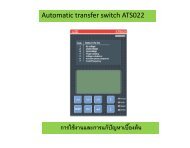
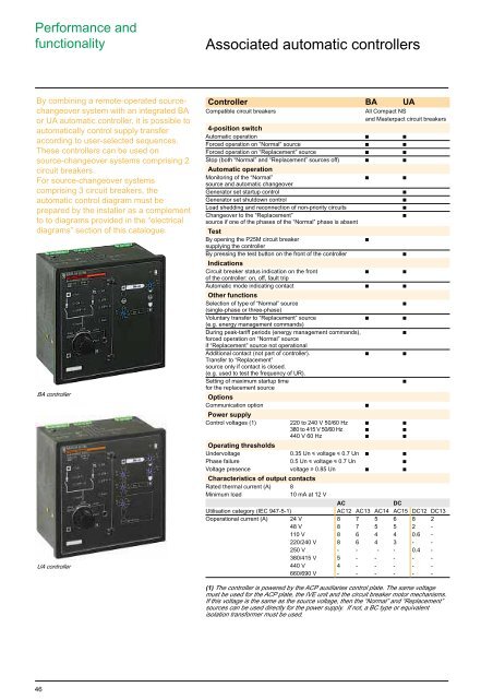
BA controller<br />
UA controller<br />
Controller BA UA<br />
Compatible <strong>circuit</strong> <strong>breakers</strong><br />
All Compact NS<br />
<strong>and</strong> Masterpact <strong>circuit</strong> <strong>breakers</strong><br />
4-position <strong>switch</strong><br />
Automatic operation c c<br />
Forced operation on “Normal” source c c<br />
Forced operation on “Replacement” source c c<br />
Stop (both “Normal” <strong>and</strong> “Replacement” sources off) c c<br />
Automatic operation<br />
Monitoring of the “Normal” c c<br />
source <strong>and</strong> automatic changeover<br />
Generator set startup control<br />
c<br />
Generator set shutdown control<br />
c<br />
Load shedding <strong>and</strong> reconnection of non-priority <strong>circuit</strong>s<br />
c<br />
Changeover to the “Replacement”<br />
c<br />
source if one of the phases of the “Normal” phase is absent<br />
Test<br />
By opening the P25M <strong>circuit</strong> breaker<br />
c<br />
supplying the controller<br />
By pressing the test button on the front of the controller<br />
c<br />
Indications<br />
Circuit breaker status indication on the front c c<br />
of the controller: on, off, fault trip<br />
Automatic mode indicating contact c c<br />
Other functions<br />
Selection of type of “Normal” source<br />
c<br />
(single-phase or three-phase)<br />
Voluntary transfer to “Replacement” source c c<br />
(e.g. energy management comm<strong>and</strong>s)<br />
During peak-tariff periods (energy management comm<strong>and</strong>s),<br />
c<br />
forced operation on “Normal” source<br />
if “Replacement” source not operational<br />
Additional contact (not part of controller). c c<br />
Transfer to “Replacement”<br />
source only if contact is closed.<br />
(e.g. used to test the frequency of UR).<br />
Setting of maximum startup time<br />
c<br />
for the replacement source<br />
Options<br />
Communication option<br />
c<br />
Power supply<br />
Control voltages (1) 220 to 240 V 50/60 Hz c c<br />
380 to 415 V 50/60 Hz c c<br />
440 V 60 Hz c c<br />
Operating thresholds<br />
Undervoltage 0.35 Un i voltage i 0.7 Un c c<br />
Phase failure 0.5 Un i voltage i 0.7 Un c<br />
Voltage presence voltage u 0.85 Un c c<br />
Characteristics of output contacts<br />
Rated thermal current (A) 8<br />
Minimum load<br />
10 mA at 12 V<br />
AC<br />
DC<br />
Utilisation category (IEC 947-5-1)<br />
AC12 AC13 AC14 AC15 DC12 DC13<br />
Ooperational current (A) 24 V 8 7 5 6 8 2<br />
48 V 8 7 5 5 2 -<br />
110 V 8 6 4 4 0.6 -<br />
220/240 V 8 6 4 3 - -<br />
250 V - - - - 0.4 -<br />
380/415 V 5 - - - - -<br />
440 V 4 - - - - -<br />
660/690 V - - - - - -<br />
(1) The controller is <strong>power</strong>ed by the ACP auxiliaries control plate. The same voltage<br />
must be used for the ACP plate, the IVE unit <strong>and</strong> the <strong>circuit</strong> breaker motor mechanisms.<br />
If this voltage is the same as the source voltage, then the “Normal” <strong>and</strong> “Replacement”<br />
sources can be used directly for the <strong>power</strong> supply. If not, a BC type or equivalent<br />
isolation transformer must be used.<br />
46