AIRS Level 1B Visible/Near-Infrared Channels ATBD - NASA's Earth ...
AIRS Level 1B Visible/Near-Infrared Channels ATBD - NASA's Earth ...
AIRS Level 1B Visible/Near-Infrared Channels ATBD - NASA's Earth ...

Create successful ePaper yourself
Turn your PDF publications into a flip-book with our unique Google optimized e-Paper software.
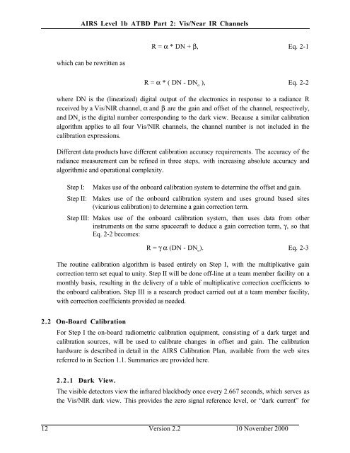
<strong>AIRS</strong> <strong>Level</strong> 1b <strong>ATBD</strong> Part 2: Vis/<strong>Near</strong> IR <strong>Channels</strong><br />
which can be rewritten as<br />
R = α * DN + β, Eq. 2-1<br />
R = α * ( DN - DN o<br />
), Eq. 2-2<br />
where DN is the (linearized) digital output of the electronics in response to a radiance R<br />
received by a Vis/NIR channel, α and β are the gain and offset of the channel, respectively,<br />
and DN o<br />
is the digital number corresponding to the dark view. Because a similar calibration<br />
algorithm applies to all four Vis/NIR channels, the channel number is not included in the<br />
calibration expressions.<br />
Different data products have different calibration accuracy requirements. The accuracy of the<br />
radiance measurement can be refined in three steps, with increasing absolute accuracy and<br />
algorithmic and operational complexity.<br />
Step I:<br />
Step II:<br />
Makes use of the onboard calibration system to determine the offset and gain.<br />
Makes use of the onboard calibration system and uses ground based sites<br />
(vicarious calibration) to determine a gain correction term.<br />
Step III: Makes use of the onboard calibration system, then uses data from other<br />
instruments on the same spacecraft to deduce a gain correction term, γ, so that<br />
Eq. 2-2 becomes:<br />
R = γ α (DN - DN o<br />
). Eq. 2-3<br />
The routine calibration algorithm is based entirely on Step I, with the multiplicative gain<br />
correction term set equal to unity. Step II will be done off-line at a team member facility on a<br />
monthly basis, resulting in the delivery of a table of multiplicative correction coefficients to<br />
the onboard calibration. Step III is a research product carried out at a team member facility,<br />
with correction coefficients provided as needed.<br />
2.2 On-Board Calibration<br />
For Step I the on-board radiometric calibration equipment, consisting of a dark target and<br />
calibration sources, will be used to calibrate changes in offset and gain. The calibration<br />
hardware is described in detail in the <strong>AIRS</strong> Calibration Plan, available from the web sites<br />
referred to in Section 1.1. Summaries are provided here.<br />
2.2.1 Dark View.<br />
The visible detectors view the infrared blackbody once every 2.667 seconds, which serves as<br />
the Vis/NIR dark view. This provides the zero signal reference level, or “dark current” for<br />
12 Version 2.2 10 November 2000