AIRS Level 1B Visible/Near-Infrared Channels ATBD - NASA's Earth ...
AIRS Level 1B Visible/Near-Infrared Channels ATBD - NASA's Earth ...
AIRS Level 1B Visible/Near-Infrared Channels ATBD - NASA's Earth ...

You also want an ePaper? Increase the reach of your titles
YUMPU automatically turns print PDFs into web optimized ePapers that Google loves.
<strong>AIRS</strong> <strong>Level</strong> 1b <strong>ATBD</strong> Part 2: Vis/<strong>Near</strong> IR <strong>Channels</strong><br />
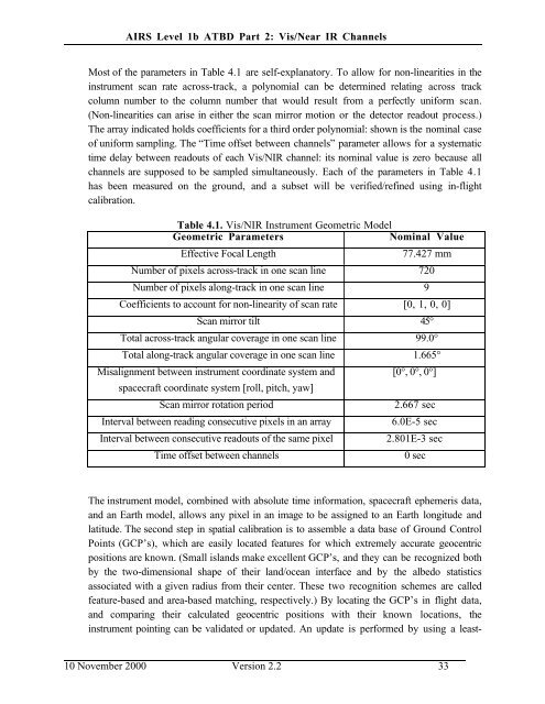
Most of the parameters in Table 4.1 are self-explanatory. To allow for non-linearities in the<br />
instrument scan rate across-track, a polynomial can be determined relating across track<br />
column number to the column number that would result from a perfectly uniform scan.<br />
(Non-linearities can arise in either the scan mirror motion or the detector readout process.)<br />
The array indicated holds coefficients for a third order polynomial: shown is the nominal case<br />
of uniform sampling. The “Time offset between channels” parameter allows for a systematic<br />
time delay between readouts of each Vis/NIR channel: its nominal value is zero because all<br />
channels are supposed to be sampled simultaneously. Each of the parameters in Table 4.1<br />
has been measured on the ground, and a subset will be verified/refined using in-flight<br />
calibration.<br />
Table 4.1. Vis/NIR Instrument Geometric Model<br />
Geometric Parameters<br />
Nominal Value<br />
Effective Focal Length<br />
77.427 mm<br />
Number of pixels across-track in one scan line 720<br />
Number of pixels along-track in one scan line 9<br />
Coefficients to account for non-linearity of scan rate [0, 1, 0, 0]<br />
Scan mirror tilt 45°<br />
Total across-track angular coverage in one scan line 99.0°<br />
Total along-track angular coverage in one scan line 1.665°<br />
Misalignment between instrument coordinate system and<br />
spacecraft coordinate system [roll, pitch, yaw]<br />
Scan mirror rotation period<br />
Interval between reading consecutive pixels in an array<br />
Interval between consecutive readouts of the same pixel<br />
Time offset between channels<br />
[0°, 0°, 0°]<br />
2.667 sec<br />
6.0E-5 sec<br />
2.801E-3 sec<br />
0 sec<br />
The instrument model, combined with absolute time information, spacecraft ephemeris data,<br />
and an <strong>Earth</strong> model, allows any pixel in an image to be assigned to an <strong>Earth</strong> longitude and<br />
latitude. The second step in spatial calibration is to assemble a data base of Ground Control<br />
Points (GCP’s), which are easily located features for which extremely accurate geocentric<br />
positions are known. (Small islands make excellent GCP’s, and they can be recognized both<br />
by the two-dimensional shape of their land/ocean interface and by the albedo statistics<br />
associated with a given radius from their center. These two recognition schemes are called<br />
feature-based and area-based matching, respectively.) By locating the GCP’s in flight data,<br />
and comparing their calculated geocentric positions with their known locations, the<br />
instrument pointing can be validated or updated. An update is performed by using a least-<br />
10 November 2000 Version 2.2 33