AIRS Level 1B Visible/Near-Infrared Channels ATBD - NASA's Earth ...
AIRS Level 1B Visible/Near-Infrared Channels ATBD - NASA's Earth ...
AIRS Level 1B Visible/Near-Infrared Channels ATBD - NASA's Earth ...

Create successful ePaper yourself
Turn your PDF publications into a flip-book with our unique Google optimized e-Paper software.
<strong>AIRS</strong> <strong>Level</strong> 1b <strong>ATBD</strong> Part 2: Vis/<strong>Near</strong> IR <strong>Channels</strong><br />
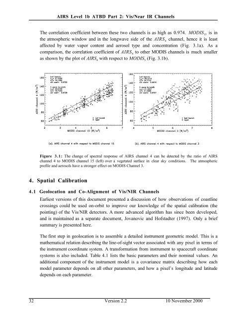
The correlation coefficient between these two channels is as high as 0.974. MODIS 15<br />
is in<br />
the atmospheric window and in the longwave side of the <strong>AIRS</strong> 4<br />
channel, hence it is least<br />
affected by water vapor content and aerosol type and concentration (Fig. 3.1a). As a<br />
comparison, the correlation coefficient of <strong>AIRS</strong> 4<br />
to other MODIS channels is much smaller<br />
as shown by the plot of <strong>AIRS</strong> 4<br />
with respect to MODIS 3<br />
(Fig. 3.1b).<br />
Figure 3.1: The change of spectral response of <strong>AIRS</strong> channel 4 can be detected by the ratio of <strong>AIRS</strong><br />
channel 4 to MODIS channel 15 (left) over a vegetated surface in clear sky conditions. The atmospheric<br />
profile and aerosols have a stronger effect on MODIS Channel 3.<br />
4. Spatial Calibration<br />
4.1 Geolocation and Co-Alignment of Vis/NIR <strong>Channels</strong><br />
Earliest versions of this document presented a discussion of how observations of coastline<br />
crossings could be used on-orbit to improve our knowledge of the spatial calibration (the<br />
pointing) of the Vis/NIR detectors. A more advanced algorithm has since been developed,<br />
and is maintained as a separate document, Jovanovic and Hofstadter (1997). Only a brief<br />
summary is presented here.<br />
The first step in geolocation is to assemble a detailed instrument geometric model. This is a<br />
mathematical relation describing the line-of-sight vector associated with any pixel in terms of<br />
the instrument coordinate system. A transformation from instrument to spacecraft coordinate<br />
systems is also included. Table 4.1 lists the basic parameters and their nominal values. An<br />
additional component of the instrument model is a covariance matrix describing how each<br />
model parameter depends on all other parameters, and how a pixel’s longitude and latitude<br />
depends on each parameter.<br />
32 Version 2.2 10 November 2000