AIRS Level 1B Visible/Near-Infrared Channels ATBD - NASA's Earth ...
AIRS Level 1B Visible/Near-Infrared Channels ATBD - NASA's Earth ...
AIRS Level 1B Visible/Near-Infrared Channels ATBD - NASA's Earth ...

Create successful ePaper yourself
Turn your PDF publications into a flip-book with our unique Google optimized e-Paper software.
<strong>AIRS</strong> <strong>Level</strong> 1b <strong>ATBD</strong> Part 2: Vis/<strong>Near</strong> IR <strong>Channels</strong><br />
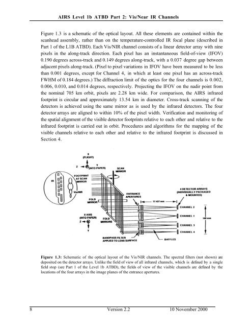
Figure 1.3 is a schematic of the optical layout. All these elements are contained within the<br />
scanhead assembly, rather than on the temperature-controlled IR focal plane (described in<br />
Part 1 of the L<strong>1B</strong> <strong>ATBD</strong>). Each Vis/NIR channel consists of a linear detector array with nine<br />
pixels in the along-track direction. Each pixel has an instantaneous field-of-view (IFOV)<br />
0.190 degrees across-track and 0.149 degrees along-track, with a 0.037 degree gap between<br />
adjacent pixels along-track. (Pixel to pixel variations in IFOV have been measured to be less<br />
than 0.001 degrees, except for Channel 4, in which at least one pixel has an across-track<br />
FWHM of 0.184 degrees.) The diffraction limit of the optics for the four channels is 0.002,<br />
0.006, 0.010, and 0.014 degrees, respectively. Projecting the IFOV on the nadir point from<br />
the nominal 705 km orbit, pixels are 2.28 km wide. For comparison, the <strong>AIRS</strong> infrared<br />
footprint is circular and approximately 13.54 km in diameter. Cross-track scanning of the<br />
detectors is achieved using the same mirror as is used by the infrared detectors. The four<br />
detector arrays are aligned to within 10% of the pixel width. Verification and monitoring of<br />
the spatial alignment of the visible detector footprints relative to each other and relative to the<br />
infrared footprint is carried out in orbit. Procedures and algorithms for the mapping of the<br />
visible channels relative to each other and relative to the infrared footprint is discussed in<br />
Section 4.<br />
Figure 1.3: Schematic of the optical layout of the Vis/NIR channels. The spectral filters (not shown) are<br />
deposited on the detector arrays. Unlike the field of view of all infrared channels, which is defined by a single<br />
field stop (see Part 1 of the <strong>Level</strong> 1b <strong>ATBD</strong>), the fields of view of the visible channels are defined by the<br />
locations of the four arrays in the image planes of the entrance apertures.<br />
8 Version 2.2 10 November 2000