
You also want an ePaper? Increase the reach of your titles
YUMPU automatically turns print PDFs into web optimized ePapers that Google loves.
Train Control Systems<br />
P.O. Box 341<br />
845 Blooming Glen Rd.<br />
Blooming Glen, PA 18911<br />
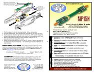
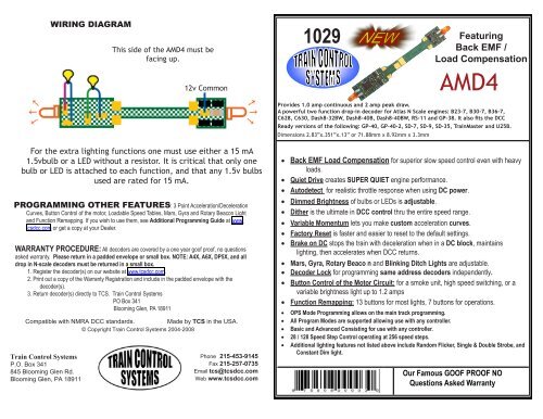
WIRING DIAGRAM<br />
This side of the AMD4 must be<br />
facing up.<br />
For the extra lighting functions one must use either a 15 mA<br />
1.5vbulb or a LED without a resistor. It is critical that only one<br />
bulb or LED is attached to each function, and that any 1.5v bulbs<br />
used are rated for 15 mA.<br />
PROGRAMMING OTHER FEATURES: 3 Point Acceleration/Deceleration<br />
Curves, Button Control of the motor, Loadable Speed Tables, Mars, Gyra and Rotary Beacon Light<br />
and Function Remapping. If you wish to use them, see Additional Programming Guide at www.<br />
tcsdcc.com or get a copy at your Dealer.<br />
WARRANTY PROCEDURE: All decoders are covered by a one year goof proof, no questions<br />
asked warranty. Please return in a padded envelope or small box. NOTE: A4X, A6X, DP5X, and all<br />
drop in N-scale decoders must be returned in a small box.<br />
1. Register the decoder(s) on our website at www.tcsdcc.com.<br />
2. Print out a copy of the Warranty Registration and include in the padded envelope with the<br />
decoder(s).<br />
3. Return decoder(s) directly to TCS. Train Control Systems<br />
PO Box 341<br />
Blooming Glen, PA 18911<br />
Compatible with NMRA <strong>DCC</strong> standards.<br />
Made by TCS in the USA.<br />
© Copyright Train Control Systems 2004-2008<br />
tm<br />
12v Common<br />
Phone 215-453-9145<br />
Fax 215-257-0735<br />
Email tcs@tcsdcc.com<br />
Web www.tcsdcc.com<br />
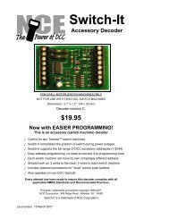
1029<br />
• Back EMF Load Compensation for superior slow speed control even with heavy<br />
loads.<br />
• Quiet Drive creates SUPER QUIET engine performance.<br />
• Autodetect for realistic throttle response when using DC power.<br />
• Dimmed Brightness of bulbs or LEDs is adjustable.<br />
• Dither is the ultimate in <strong>DCC</strong> control thru the entire speed range.<br />
Featuring<br />
Back EMF /<br />
Load Compensation<br />
Provides 1.0 amp continuous and 2 amp peak draw.<br />
A powerful two function drop-in decoder for Atlas N Scale engines: B23-7, B30-7, B36-7,<br />
C628, C630, Dash8-32BW, Dash8-40B, Dash8-40BW, RS-11 and GP-38. It also fits the <strong>DCC</strong><br />
Ready versions of the following: GP-40, GP-40-2, SD-7, SD-9, SD-35, TrainMaster and U25B.<br />
Dimensions 2.83”x.351”x.13” or 71.88mm x 8.92mm x 3.3mm<br />
AMD4<br />
• Variable Momentum lets you make custom acceleration curves.<br />
• Factory Reset is faster and easier to reset to the default settings.<br />
• Brake on DC stops the train with deceleration when in a DC block, maintains<br />
lighting, then accelerates when <strong>DCC</strong> returns.<br />
• Mars, Gyra, Rotary Beaco n and Blinking Ditch Lights are adjustable.<br />
• Decoder Lock for programming same address decoders independently.<br />
• Button Control of the Motor Circuit: for a smoke unit, high speed switching, or a<br />
variable brightness light up to 1.2 amps<br />
• Function Remapping: 13 buttons for most lights, 7 buttons for operations.<br />
• OPS Mode Programming allows on the main track programming.<br />
• All Program Modes are supported allowing use with any controller.<br />
• Basic and Advanced Consisting for use with any controller.<br />
• 28 / 128 Speed Step Control operating at 256 speed steps.<br />
• Additional lighting features not listed above include Random Flicker, Single & Double Strobe, and<br />
Constant Dim light.<br />
Our Famous GOOF PROOF NO<br />
Questions Asked Warranty
WORKSHEET INSTRUCTIONS<br />
• A blank outlined box is provided by each CV number. This is so you can preplan your<br />
decoder and have a record of your choices.<br />
• In many cases you are recording a single value such as an address, a rate, or a limit.<br />
• In some cases you are choosing more than one value such as actions, functions, or buttons.<br />
Each of these will have a value. Add the values of those you want active and enter that<br />
sum in the blank box.<br />
• The other box by the CV number is the factory set value. If it is shaded, it can be reset with<br />
Factory Reset.<br />
BASIC CONFIGURATION<br />
the values Circle by all of the changes you want to make.<br />
A 0 1 Reverse the direction the engine runs.<br />
1<br />
B 2 -2 Use 14 Speed Steps instead of 28/128.<br />
C 4 -4 Disable analog ( DC ) operation.<br />
D 0 16 Make the Loadable Speed Tables active.<br />
E 0 32 Make the decoder address 128 or higher.<br />
CV 29 6 Adjust the Default Value by the values you have circled.<br />
ADDRESSING<br />
2 Digit Address Use if the address is 127 or less.<br />
2 CV 1 3 Record your choice here.<br />
4 Digit Address Make sure Table 1 “E” = 32.<br />
3 Your command station will assign the values of CV 17 and CV18<br />
CV 17 0 Record your four digit address here<br />
CV 18 0<br />
For more <strong>information</strong> about CV 17 and 18 visit our web entry on this topic at:<br />
http://www.tcsdcc.com/faq/four_digit_addressing.htm<br />
Consist Address<br />
If this is greater than 0, the regular address is unalterable.<br />
4 Add 128 to reverse the loco when in consist. Some systems only!<br />
CV 19 0 Use a 2 digit address when in a consist ( Multiple units ).<br />
Decoder Lock Same address decoders need a different sub address in CV 16.<br />
To unlock a decoder, make CV 15 = 0 or CV 15 = CV 16.<br />
To lock a decoder, make<br />
5<br />
CV 15 not equal to CV 16. To lock all same address decoders, make CV 15 = 7.<br />
CV 15 0 All unlocked = 0 Decoder to unlock = 1 - 6 All locked = 7<br />
CV 16 1 Mobil = 1 Sound = 2 Light Only = 3 ___ = 4 ___ = 5 ___ = 6<br />
MOTOR CONTROL<br />
Speed Graph 1 volt = 18 0 produces straight line acceleration.<br />
6<br />
CV 2 0 Start Volts Set the voltage when the throttle is first applied.<br />
CV 6 0 Mid Volts Set the voltage when the throttle is at midpoint.<br />
CV 5 0 Top Volts Set the voltage when the throttle is at full speed.<br />
Momentum<br />
The effect of engines starting and stopping heavy loads.<br />
CV 3 1 Acceleration Larger values add time to each speed step.<br />
7<br />
CV 4 1 Deceleration Larger values add time to each speed step.<br />
CV 23 0 *Acceleration Adjustment when in Consist<br />
CV 24 0 *Deceleration Adjustment when in Consist<br />
*Values above 128 increase the adjustment * Values below 128 decrease the adjustment<br />
Dither<br />
If BEMF is turned off dither can provide an alternate form of speed control.<br />
10<br />
CV 56 3 Dither Frequency The highest frequency = 1.<br />
CV 57 10 Dither Voltage The lowest voltage = 1.<br />
NOTE: Both CV 56 and CV 57 must be greater than 0 for Dither to be active.<br />
Back EMF, Rule 17 Dimming Options and Opposite Dim Control<br />
If BEMF is enabled Dither is disabled. If BEMF is disabled Dither is automatically enabled based on the values<br />
of CV56 and CV57. To adjust dither set CV57 to a recommended value of 15, if there isn’t movement at 2%<br />
throttle setting, increase CV57 by 5 until you have movement of the flywheel. To fine tune the speed, change CV<br />
56 by 1 until it is running as desired.<br />
Even number OR 0= BEMF OFF Odd number = BEMF ON<br />
BEMF disabled =0 BEMF enabled = 1 BEMF button control= 3 Dims when stopped = 16<br />
To turn on BEMF and function button control of it, put 3 into CV 61 Opposite light is dimmed = 32<br />
13<br />
CV 61 1 BEMF and Dimming Control BEMF+Stopped + Opposite dim = 49<br />
CV 136 2 Function button control of BEMF Bits 0-7 designates buttons 5-12<br />
CV 64 15 Dimmed Brightness ( 2 – 6 for LEDs, 12 – 18 for Bulbs )<br />
CV 10 0 BEMF Cut Out<br />
For more <strong>information</strong> go to www.tcsdcc.com/BEMF.pdf<br />
LIGHTING CONTROL<br />
Light Function Wires<br />
Light Effect fwd rev both<br />
CV 49 0 White Wire<br />
Constant Bright Light 0 16 32<br />
11 CV 50 16 Yellow Wire<br />
Random Flicker (fire box) 1 17 33<br />
CV 51 32 Green Wire<br />
Mars Light 2 18 34<br />
CV 52 32 Purple Wire<br />
Flashing Light 3 19 35<br />
Place the value attained from the table by<br />
Single Pulse Strobe 4 20 36<br />
the function wire that will control it.<br />
Double Pulse Strobe 5 21 37<br />
* Auto-Mars: Automatically turns Mars<br />
Rotary Beacon 6 22 38<br />
light on when decelerating below 36%<br />
Gyra Light 7 23 39<br />
speed. This setting also turns the Mars<br />
Rule 17 (dimmable light) 8 24 40<br />
light on steady above 36% speed.<br />
Ditch Light ( Left or Right ) 10 26 42<br />
Ditch Light ( Other side ) 11 27 43<br />
Rule 17 must be enabled in table 11 to<br />
Constant Dim light ( 50% ) 12 28 44<br />
*Auto-Mars 13 29 45<br />
enable dimming options in table 13.<br />
Analog ( DC ) Power Control<br />
Turn off Black or Red wire powered functions.<br />
-<br />
17<br />
CV 13 255 Activate power to light functions on DC<br />
Brake on DC Activate by subtracting 4 from CV 29 in table 1.<br />
Consist Lighting Control<br />
18 CV 21 0 Extra Functions Green and Purple wire = 3<br />
CV 22 0 Headlight Functions White and Yellow Wire = 3<br />
Factory Reset<br />
Sets all CVs with a shaded value back to that value.<br />
20 CV 8 153 Enter 2 to perform a Factory Reset.