Switch-It C.pdf - DCC Concepts
Switch-It C.pdf - DCC Concepts
Switch-It C.pdf - DCC Concepts

Create successful ePaper yourself
Turn your PDF publications into a flip-book with our unique Google optimized e-Paper software.
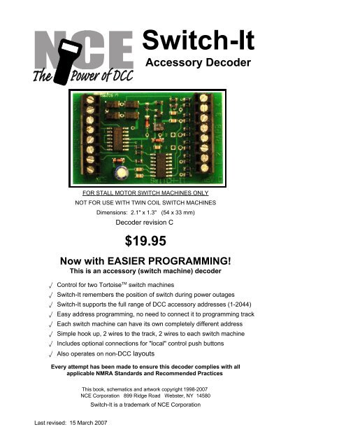
<strong>Switch</strong>-<strong>It</strong>Accessory DecoderFOR STALL MOTOR SWITCH MACHINES ONLYNOT FOR USE WITH TWIN COIL SWITCH MACHINESDimensions: 2.1" x 1.3" (54 x 33 mm)Decoder revision C$19.95Now with EASIER PROGRAMMING!This is an accessory (switch machine) decoder‚ Control for two Tortoise TM switch machines‚ <strong>Switch</strong>-<strong>It</strong> remembers the position of switch during power outages‚ <strong>Switch</strong>-<strong>It</strong> supports the full range of <strong>DCC</strong> accessory addresses (1-2044)‚ Easy address programming, no need to connect it to programming track‚ Each switch machine can have its own completely different address‚ Simple hook up, 2 wires to the track, 2 wires to each switch machine‚ Includes optional connections for "local" control push buttons‚ Also operates on non-<strong>DCC</strong> layoutsEvery attempt has been made to ensure this decoder complies with allapplicable NMRA Standards and Recommended PracticesThis book, schematics and artwork copyright 1998-2007NCE Corporation 899 Ridge Road Webster, NY 14580<strong>Switch</strong>-<strong>It</strong> is a trademark of NCE CorporationLast revised: 15 March 2007
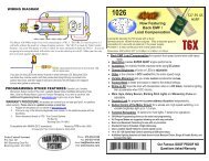
Installation Notes:This decoder is designed to control Tortoise, <strong>Switch</strong>Master or other low current "stallmotor" switch machines. The outputs are rated for 50mA maximum. Most Tortoisemachines draw 20 to 25mA with normal track voltage (about 13-15 volts). We usedouble sided foam tape to mount the <strong>Switch</strong>-<strong>It</strong> to the side of a Tortoise.Wiring:See the diagram below for wiring particulars. The only required wires are two wires tothe track and two wires to each machine. <strong>It</strong> is OK to use the <strong>Switch</strong>-<strong>It</strong> for control of onlyone machine.To TrackSWITCH-IT wiring diagramSWITCHMACHINE"A"TRK SWA SWBNCE SWITCH-IT1 2 3 4PBPAREV C4321SWITCHMACHINE"B"Tortoise MachinesIllustrated aboveOPTIONAL"Local" control push buttonscan be mounted on fascia,control or dispatcher panelsDo not connect decoder commonto the common of other <strong>Switch</strong>-<strong>It</strong>sOptional push buttons:Push buttons may be added for local control of the switches. Buttons 1 and 2 controlswitch "A" and buttons 3 and 4 control switch "B". Use momentary contact switchesfor local control. Do not use a toggle switch (unless it is momentary), its continuousconnection will prevent <strong>DCC</strong> control of the turnout. In the illustration above the pushbutton terminals filled in with black are "common" with each other. Buttons 1 and 2 areshown wired with a common wire to each push button as are buttons 3 and 4. <strong>It</strong> is OKto use only one common wire for all 4 push buttons. You can have multiple buttonswired in parallel for operation of the machine from more than one control panel. If the<strong>Switch</strong>-<strong>It</strong> is used on DC (12-16 volts DC) the buttons will still work.You can also program the <strong>Switch</strong>-<strong>It</strong> to “toggle” the outputs with each push of the localcontrol pushbuttons. Button 1 will control the SWA output and button 4 will control theSWB output. Buttons 2 and 3 will be ignored and are not needed.<strong>Switch</strong> machine mounting tip:On our Tortoise machines we use hot glue to mount the machine. The glue staysliquid just long enough after application to allow alignment of the machine. Wemanually center the arm of the machine then slide the machine around while the gluesets to align the points to the middle of their throw. The low temperature hot glue isweak enough to allow removal of the machine later on by prying with a putty knife.Use a throw wire that is about 6” (150mm) longer than the one provided with theTortoise to give you room to put glue on the machine after the wire is put through theroadbed.Last revised: 15 March 2007Page2
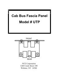
Programming informationThe <strong>Switch</strong>-<strong>It</strong> cannot be programmed on your programming track. <strong>It</strong> is alwaysprogrammed while connected to the mainline track. This decoder can be programmedby all systems that support accessory control using the procedure below.To program switch "A" to a new address using any <strong>DCC</strong> system:1) Connect wires from the track to the decoder TRK connections.2) Connect a short "jumper" wire from the PA terminal to common as shown below.3) Use your <strong>DCC</strong> system to throw the accessory (switch) number you want the<strong>Switch</strong>-<strong>It</strong> to use as its new address.To throw a switch using the NCE or MRC system:Press “SEL ACCY”Type in the accessory number followed by “ENTER”Push “1” to throw the switch.To throw a switch using a Digitrax system:Press “SWCH”Type in the accessory numberPush “OPTN” to throw the switch.To throw a switch using a Lenz system:Press “F”Press “5”Type in the accessory number followed by “ENTER”Push “+”4) Remove the jumper wire.Do not leave the jumper in place after programming or you won’t be able tocontrol the switch.To program switch "B" to a new address using any <strong>DCC</strong> system:1) Connect wires from the track to the decoder TRK connections.2) Connect a short "jumper" wire from the PB terminal to common as shown below.3) Use your <strong>DCC</strong> system to control the accessory (switch) number you wish thedecoder to use as its address for the SWB output. (see step 3 above)4) Remove the jumper wire.Do not leave the jumper in place after programming or you will not be able tocontrol the switch.TO TRACKTRK SWA SWBRST1 2 PA PB 3 4"Jumper" wireto program SWB"Jumper" wireto program SWANCE SWITCH-IT REV CInstall only ONE jumper at a time when programming accessory addressesLast revised: 15 March 2007Page3
Set pushbutton 1 to "toggle" the SWA output (disables pushbutton 2):NCE Power Pro TM or PowerCab TM users can use the PROG ACCESSORIESfeature of your system. Set CV548 = 1 (use the accessory address of SWA) toenable the ‘toggle’ option or set CV548 = 0 to disable it.If you have another brand of <strong>DCC</strong> system use the following procedure:1) Disconnect track power to the <strong>Switch</strong>-<strong>It</strong>.2) Connect PA to the right hand RST terminal indicated by the arrow in the abovefigure.3) Reconnect track power to the <strong>Switch</strong>-<strong>It</strong>4) Remove the PA to RST jumperSet pushbutton 4 to "toggle" the SWB output (disables pushbutton 3):NCE Power Pro TM or PowerCab TM users can use the PROG ACCESSORIESfeature of your system. Set CV549 = 1 (use the accessory address of SWB) toenable the ‘toggle’ option or set CV549 = 0 to disable it.If you have another brand of <strong>DCC</strong> system use the following procedure:1) Disconnect track power to the <strong>Switch</strong>-<strong>It</strong>.2) Connect PB to the right hand RST terminal indicated by the arrow in the abovefigure.3) Reconnect track power to the <strong>Switch</strong>-<strong>It</strong>4) Remove the PB to RST jumperTo set the <strong>Switch</strong>-<strong>It</strong> to "exercise" the switch points at each power up:NCE Power Pro TM or PowerCab TM users can use the PROG ACCESSORIESfeature of your system. Set CV547 = 1 (use the accessory address of SWA) toenable the ‘exercise’ option or set CV547 = 0 to disable it.If you have another brand of <strong>DCC</strong> system consult your manual for programming ofaccessories in Operations mode.Legacy OPS programming disable (CV554):There are two methods for programming accessory decoders “on the main” (OPSmode programming). Legacy mode, in use since 1995, is being phased out by theNMRA and replaced by the current, newer method. The <strong>Switch</strong>-<strong>It</strong> supports bothkinds of programming on the main.NCE Power Pro TM or PowerCab TM users can use the PROG ACCESSORIESfeature of your system. Disable Legacy mode by setting CV554 to a value of 1. Ifyou disable legacy mode and find you can no longer program the decoder with yoursystem, your system only supports legacy mode. You can re-enable Legacy modeby resetting the <strong>Switch</strong>-<strong>It</strong> back to factory defaults as described below.If you have another brand of <strong>DCC</strong> system consult your manual for programming ofaccessories in Operations mode.Pushbutton lockout (CV556):On some layouts it may be desirable to disable operation of the local controlpushbuttons. NCE Power Pro TM or PowerCab TM users can use the PROGACCESSORIES feature of your system.Set CV556 = 1 to disable the optional pushbutton inputs. CV556 = 0 enables thebuttons.You can disable or enable ALL decoders on the layout at the same time by usingthe accessory decoder broadcast address of 2044 when programming CV556.If you have another brand of <strong>DCC</strong> system consult your manual for programming ofaccessories in Operations mode.Last revised: 15 March 2007Page4
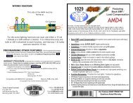
Factory reset:Momentarily connecting the two RST terminals will reset the decoder to the originalfactory settings as indicated below.Factory default values for decoderOutput SWA is factory programmed to accessory address 1 (decoder addr 1, output 1)Output SWB is factory programmed to accessory address 2 (decoder addr 1, output 2)CV547 is set to 0 (Power up exercising of switch machine disabled)CV548 is set to 0 (use pushbutton 1 to “toggle” output SWA, pushbutton 2 is disabled)CV549 is set to 0 (use pushbutton 4 to “toggle” output SWB, pushbutton 3 is disabled)CV554 is set to 0 (legacy accessory OPS programming enabled)CV556 is set to 0 (pushbutton lockout is disabled)Other technical stuff:vWe have successfully controlled two Tortoise switch machines with one decoderoutput when used in a crossover. We can't guarantee this will work in all cases.vThe outputs of the decoder are always on to prevent the switch machine from backingoff due to the springiness of the turnout throw mechanism.vIf CV547 is programmed to 1 (“exercise” enabled) the decoder will "back off" theswitch (usually about halfway) then return the switch to its remembered position atpower up. This is to make sure the points are fully thrown (solves sticky pointproblems).vSee the diagram below for turnout position indicator light wiring. LEDs are wired inseries with the switch machine to indicate which position the turnout is thrown. MostLEDs will handle up to 25mA, the switch motor acts as the current limiting device forthe LEDs. We use red and green LEDs but any color will do. The switch machine willrun a bit slower with LEDs installed due to about a 1.5 volt loss in the LED.TortoiseMachineShownLEDsREDTRK SWA SWBGREENLast revised: 15 March 2007Page5
TIP:If you use power routing turnouts such as Peco Electro-Frog, Shinohara or Waltherswe suggest wiring a #1156 automotive taillight bulb in series with the points of theturnout (see above). This will prevent short circuits from shutting down your powerbooster in the event you enter the turnout from the frog end without aligning the points.TortoiseMachineShown#1156BulbWarning: This product contains chemicals known to the State ofCalifornia to cause cancer, birth defects or other reproductive harm.WarrantyThis decoder is fully factory tested and warranted against manufacturing defects for aperiod of 1 year. As the circumstances under which this decoder is installed can not becontrolled, failure of the decoder due to installation problems can not be warranted. Thisincludes misuse, miswiring, operation under loads beyond the design range of thedecoder or short circuits in the locomotive manufacturer’s factory wiring. The warranty isvoided if the decoder is miswired, connected to more than 22 volts, or used with switchmotors drawing more than 40mA.If the decoder fails for non-warranted reasons NCE will replace the decoder, no questionsasked, for $10 US plus $2 shipping. For warranty or non-warranty replacement send thedecoder (an any payment, if required) to:NCE Warranty Center 899 Ridge Road Webster, New York 145800524011405240114The terms Silent Running, Power Pro, PowerCab , ProCab, <strong>Switch</strong>-<strong>It</strong>, Snap-<strong>It</strong>, the NCE logo with “Power of <strong>DCC</strong>” slogan aretrademarks of NCE Corporation. Digitrax is a trademark of Digitrax Inc. Tortoise is a trademark of Circuitron, Inc. MRC is atrademark of MRC Corporation. The distinctive shape of the ProCab when used with a thumbwheel speed control and LCDdisplay is a trademark of NCE Corporation.Last revised: 15 March 2007Page6