LH90 Manual version 3.6 - Lenz USA
LH90 Manual version 3.6 - Lenz USA
LH90 Manual version 3.6 - Lenz USA

You also want an ePaper? Increase the reach of your titles
YUMPU automatically turns print PDFs into web optimized ePapers that Google loves.
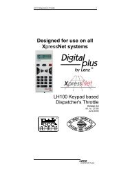
<strong>LH90</strong> Engineer’s Throttle V<strong>3.6</strong> 1Designed for use on allXpressNet systems<strong>LH90</strong> Engineer’s ThrottleVersion <strong>3.6</strong>art. no. 21090June 2008
<strong>LH90</strong> Engineers Throttle 3Welcome!Congratulations for purchasing the Digital plus by <strong>Lenz</strong> ® <strong>LH90</strong>throttle. We wish you much enjoyment with using this XpressNetbased throttle with your NMRA DCC model railroad controlsystem.The <strong>LH90</strong> hand held controller is a universal data input device inthe Digital plus by <strong>Lenz</strong> ® system. With it you can:- operate your locomotives- use smart-consisting to assemble, operate, and disassemble multiunitconsists.- throw turnouts, set signals or activate uncoupling tracks- program locomotive and accessory decoders as well as feedbackdevices- read out and set handheld configurationsThis operation manual is intended to make using the <strong>LH90</strong> easy for you.To get started, first read the section “First Steps". After you haveunderstood the basic locomotive control, you can familiarize yourself withthe full range of functions of this hand held controller step by step and putthem to use.If after reading this operating manual you have unanswered questions,please contact your dealer or <strong>Lenz</strong> directly. You can contact us in thefollowing ways:Postaladdress:Europe<strong>Lenz</strong> Elektronik GmbHHuettenbergstrasse 29D-35398 GiessenNorth America<strong>Lenz</strong> AgencyPO Box 143Chelmsford, MA 01824Phone ++49 (0) 6403 900 133 ++1 978 250 1494Fax ++49 (0) 6403 900 155 ++1 978 455 LENZEmail info@digital-plus.de support@lenz.comDo you have everything?You should have the <strong>LH90</strong>, Coil cord and DIN and <strong>Manual</strong>.If an item is missing, please contact your retailer or <strong>Lenz</strong> to havethe item replaced.
<strong>LH90</strong> Engineers Throttle 41 OverviewImportant advice, please read first!Your <strong>LH90</strong> hand held throttle is a component of yourDigital plus by <strong>Lenz</strong> ® system and was submitted to intensivetesting before delivery. <strong>Lenz</strong> Elektronik GmbH guarantees faultfreeoperation if the advice given below is followed:The <strong>LH90</strong> is authorized for operation only with a system that fullysupports XpressNet such as any Digital plus by <strong>Lenz</strong> ® system.Any use other than the one described in this operating manual isnot permitted and all guarantees become invalid if the <strong>LH90</strong> isused in an inappropriate way.The operation of <strong>LH90</strong> requires Digital plus system <strong>version</strong> 3 orgreater. The <strong>LH90</strong> cannot to be used with devices which use oldersoftware <strong>version</strong>s. Do not connect the <strong>LH90</strong> to any other device. Even if otherdevices use the same connectors, you must not operate the<strong>LH90</strong> with those devices. The fact that the connectors aresimilar does not automatically mean that you may use themfor operation, even if you are dealing with other modelrailroad control systems.Do not expose the <strong>LH90</strong> to moisture or direct sunlight.1.1 The range of functions of the <strong>LH90</strong>• With the <strong>LH90</strong> you may control up to 9999 digital locomotivesindependently. With address 0 you control a conventionallocomotive without a decoder with your system.• You can address up to 28 functions in your locomotivedecoders, if your command Station supports F0 and F1-28.You can on a locomotive per locomotive basis set F1-F28 tobe momentary or on/off.• Depending on the command station used (LZ100, LZV100,SET02, “compact”), you can control, assemble and deletemultiple units (consists).• You can set the running-notches (speed steps) mode for thelocomotive address currently displayed.• Locomotive features such as starting and braking delay canbe set through "programming on the main" (operations modeprogramming) or through "programming in service mode".4
<strong>LH90</strong> Engineers Throttle 5• The <strong>LH90</strong> can also switch turnouts. Depending on thecommand station used, you can switch up to 999 turnouts(and signals).1.2 What’s New in Version <strong>3.6</strong>?We have added several major improvements in Version <strong>3.6</strong>. TheseInclude Shortcut Menu Keys for the most important operations supportfor functions F1-F28, ability to set up momentary functions andimproving throttle handoff of operating locomotives.1.3 Notations and symbols:(P. 23) This shift indicates particular pages of the operatingmanual which contain further information on the subject underdiscussion. Texts marked with this symbol and a frame containinformation and advice of special importance.2 Your First <strong>LH90</strong> Session2.1 Connecting the <strong>LH90</strong> to your DCC SystemPlug one end of the coil cable with the phone connector into thesocket of the <strong>LH90</strong>. Pug the end of the cable with the 5 pin dinplug into your Digital plus by <strong>Lenz</strong> ® XpressNet.As is the case with all XpressNet devices, your <strong>LH90</strong> can bedisconnected and reconnected during operation. To make use ofthis feature of XpressNet, install several LA152 adapters or dinsockets around your layout. This keeps operators close to theaction.Connecting to a LZ100 or LZV100 command stationPlug the 5-pole DIN-plug- into the 5-pole DIN-socket at the rear of your LZ100/LZV100or- into a LA152 adapter (or Atlas Panel #322), or din socket on theback side of the Command Station, the LZ100/LZV100.Connecting to a "compact" or Atlas CommanderPlug the 5-pole DIN-plug into a LA152 adapter or din socket that isconnected to the "compact" or Atlas Commander.
<strong>LH90</strong> Engineers Throttle 6Setting the XpressNet addressFor fault-free exchange of information with the command station,each input device connected to the XpressNet must have its ownunique device address. It is necessary to ensure that allconnected devices have different addresses. Up to 31 devices canbe connected to the XpressNet, i.e. the addresses 1 to 31 can beused. From the factory each <strong>LH90</strong> throttle is set to the address 02.If you are already operating another XpressNet device with thisaddress, you will have to assign a different address to your <strong>LH90</strong>.You will find information on the setting of the XpressNet addressin section 13.1 (P. 35).2.2 Running trains the first timeWe assume in this example that you are operating a locomotivewith the address "3". On delivery you can access the addresses 1to 8 quickly and easily by pressing key "A" repeatedly.1. Connect your <strong>LH90</strong> to your Digital plus system (P. 5)2. Place the locomotive with address 3 on the track.3. Turn the rotary control-knob to the left-hand limit-stop.4. If the number 3 is not on the display, press the "A" key repeatedly untiladdress "3" is shown on the display.5. 5.1 If there are no flashing dots on the display, set the direction switch to up.(direction of locomotive is forward)5.2 If you see a flashing dot in the centre of the display "0003", the <strong>LH90</strong> isinstructing you which way the direction switch must be set to control thelocomotive. To control the locomotive, set the direction-switch as follows:Up, when the upper dot flashes.6. Turn the rotarycontrol-knob to theright. The locomotivespeeds up.Down, when the lower dot flashes.Turn the rotarycontrol-knob to theleft. The locomotiveslows down.Turn the knob as far to the left as possible: the locomotive stops.6
<strong>LH90</strong> Engineers Throttle 77.Flick the direction-switchdownwards through the centreposition. This will change thedirection of motion of thelocomotive from forwards tobackwards.If you flick the direction-switch to the centreposition while the locomotive is in operation,the locomotive will stop with the amount ofdelay in braking that is set in the locomotivedecoder. If you afterwards flick the switch in adifferent direction, the locomotive will speedup again, also with the amount of delay that isset in the decoder.8. In order to switch on the light function of the locomotive decoder, presskey "0 M ". Press the key once and you will turn the light on, press itagain and you will turn it off.3 The operational controls of the <strong>LH90</strong>In this section you will learn about:- the display information and how it is presented in theoperating manual- the functioning of the <strong>LH90</strong> rotary control-knob- the functioning of the direction switch- the functions of the <strong>LH90</strong> keys3.1 The LED displayThe <strong>LH90</strong> has a luminescent, 4-digit LED display. Each digit isable to display the numbers 0 to 9 as well as other specialsymbols.In normal operation the address of the locomotivewhich you are presently controlling is constantly shown.Dots below left, in the centre and below right are helpfulfor- adjusting the direction switch when you take overa different locomotive.- showing the functions which are on or offYou will find more detailed information on this below.In this operating manual the display is presented as follows:
<strong>LH90</strong> Engineers Throttle 93.5 Emergency Stop KeyIf you want to immediately stop operation press thekey.The voltage on the track will be switched off, and all locomotiveswill immediately stop. During an emergency stop, the LED of thepower station LZV flashes, and the <strong>LH90</strong> display flashes. Whenever “OFF” flashes in the display the system hasbeen shut off. To resume operation, press thekey again.You can customize the operation of the EmergencyStop key. See section 13 (P. 33)4 Operating LocomotivesIn this section you will learn about:- the <strong>LH90</strong>s stack- how you select a locomotive address that is in the stack- setting the direction switch and rotary control knob to matchthe locomotives speed and direction- how to acquire a locomotive that is being used by anotherhandheld- how to control the locomotives functions4.1 The <strong>LH90</strong>s stackThe <strong>LH90</strong> contains a stack of 8 current locomotive addresses thatthe <strong>LH90</strong> can quickly switch between. When you plug your <strong>LH90</strong>into your XpressNet, the displays shows the address of thelocomotive that is being controlled. To control a differentlocomotive you will have to select a different address. There aretwo ways of changing the address of the locomotive that the <strong>LH90</strong>will control.Either you scroll through the stack until the desired address isdisplayed or, if the address is not currently in the stack, enter anew address in the stack.4.1.1 Scrolling through the stackThe “stack” of addresses facilitates quick access to up to 8locomotive addresses. The stack size is adjustable from 2 to 8address slots using the SYS menu (see section 13). Each positionwithin of the stack can be assigned to any locomotive address
<strong>LH90</strong> Engineers Throttle 10between 0 and 9999. From the factory the stack size is set to 8and the loco addresses 1 to 8 are located in the stack. Changingthe address contained in a stock location is easy and is shown inthe Address Menu section (see section 6 P. 15). The stack sizecan be changed by changing a system setting. See section 13(P. 33). The locomotive addresses entered in the stack areremembered by the <strong>LH90</strong>, even if the <strong>LH90</strong> is switched off.When pressed, this key causes the <strong>LH90</strong> to display the next locomotiveaddress in the stack. Having reached the bottom of the list, the followingkey stroke will again display the locomotive address at the top of the list.This means that you are scrolling through the stack in a forwardsdirection.When you hold the "A" down, the current stack location is displayed.Press "Shift" and then "A" to switch to the previousaddress in the stack or scroll backwards through thestack. If the locomotive address is an MU address (see section7 for an explanation of MUs) then Shift “A” will scrollbetween different locomotives within the MU. If the display is blinking this means that another throttlecurrently has control of the locomotive. If you changethe speed or change a function you take control fromthe other throttle and his or her display will startblinking.4.2 Adjusting the rotary control-knob position tothe speed of the selected locomotiveIf the direction switch is in the forward or reverse position and youmove the knob, the locomotive will immediately change its speedto the new knob position. To prevent an immediate change inspeed, it is often better to adjust the position of the rotary controlknobin the manner described below before taking control of thelocomotive. This step is totally optional.After having selected the desired address, and before moving therotary know, the display will indicate in which direction you have tomove the rotary control-knob so that the speeds of the knob andlocomotive match.10
<strong>LH90</strong> Engineers Throttle 11If you wish to adjust the rotary control knob, but do not wish toaffect the speed of the locomotive move the direction switch to thecenter position. Once the direction switch is in the center positionyou can adjust the rotary control knob until the center led is litindicating that the speeds of the locomotive and knob are thesame. This optional step is only necessary if the position of theknob is different from the speed of the locomotive you wish tocontrol.After you are satisfied that the speeds are similar or match set thedirection switch to the desired position. Once the direction switchis set turning the knob will cause the speed of the locomotive tochange.4.3 Setting the Direction Switch for the correctdirection of travelBefore you can control the locomotive the direction switch mustmatch the direction of travel the locomtive was last run in. Onceyou have the address of the locomotive on the display and youhave optionally adjusted the position of the rotary control knob,you still need to set the direction switch to the correct position asindicated by the LED in the center of the display..Dot is not flashing:direction switch is in correct position. Takeover the locomotive by turning the rotarycontrol-knob.Dot is flashing:direction switch is in wrong position. Inorder to take a locomotive over, simplychange the position of the direction switch.
<strong>LH90</strong> Engineers Throttle 12 You will immediately take over control of the locomotiveaddress that is in the display by moving the rotarycontrol-knob once the direction switch is in the correctposition. You will know that this is the case when thedirection LED in the centre is not flashing.4.4 Quick function accessThe <strong>LH90</strong> can address up to 29functions of a locomotivedecoder. The status of thefunctions is displayed by dots onthe display. The status ofFunctions F0-F4 is normallydisplayed. After the shift key hasbeen pressed and released thestatus of F5-F8 are displayedinstead of F1-F4 until another keyis pressed. All Functions F1-28can be accessed via the FuncMenu (see section 9 P. 28)The functions 0 to 4 can be switched on and off by pressing thekey once.switches function 0 on or off(normally the direction-dependentfront lighting).switches function 2 on or off.switches function 1 on oroff.switches function 3 on oroff.12
<strong>LH90</strong> Engineers Throttle 134 8 switches function 4 on or off.For functions 5 to 8 you need 2 keystrokes.switches function 5on or off.switches function 6on or off.switches function 7on or off. 4 8 switches function 8on or off.Of course you can only use these functions if the decoder installedin the locomotive has corresponding function outputs and if theseare connected to specific functions within the locomotive (lighting,smoke generator, coupling, sound and so on).5 The menusThe <strong>LH90</strong> is a powerful handheld with a lot of unique features.These features are accessed by selecting a specific menu.Whether you can access all the menus listed, will depend on thecommand station (LZ100, LZV100, SET02, “compact”) to whichyou have connected your <strong>LH90</strong>. All the <strong>LH90</strong> menus are accessedin the same way:First press the "shift" key. On the display a dot will appear on the upperright hand side.You can now scroll through the menus using this key. Press the keybriefly to scroll “forwards“(sequence as shown below). Press and hold thekey a little bit longer before releasing to scroll “backwards“.Key Display DescriptionUsed to enter a new loco address into thestack. (see section 6 P.15)Used to add a locomotive to a multi-unit.(see section 7 P. 16)Used to remove a locomotive from a multiunit.(see section 7 P.19)Used to access the programming submenu when you want to read or setspecific values within a decoder. (seesection 8 P. 22 )Used to read or set specific system or<strong>LH90</strong> settings. (see section 13 P. 33 )
<strong>LH90</strong> Engineers Throttle 14Used to access functions groups 1,2,3 (orF1-28). (see section 9 P. 28 )Used to set momentary functions (latchingor non-latching). (see section 10 P. 30 )Used to switch turnouts and signals. (seesection 11 P. 30 )Used to display or set the current numberof speed steps being used by the <strong>LH90</strong> forthe locomotive address that was beingdisplayed before the menu was entered.(see section 12 P. 31 )The "A" key is always used to select the menu that is shown onthe display. After selecting with the “A” refer to the instructionsspecific to that menu. The <strong>LH90</strong> "remembers" the menu which was chosen last,even after the <strong>LH90</strong> has been switched off. Whenever youchange a menu, the menu last selected is displayed first. If you wish to leave the menu selection and return to the lastoperation, press the key Use the Shortcut Menu keys to quickly go to common menus(see section 5.2 below)5.1 Entering a number into the menuTo enter numbers (such as a locomotiveaddress) within a menu, always follow thesame procedure:Use key 1 to alter the first digit from the left;use key 2 to alter the second digit from the leftand so on. Use key 4 to alter the fourth digitfrom the left.See the illustration opposite for the allocationshown on the <strong>LH90</strong>. The lines show you whichkey controls which digit.Press the key briefly to increase the displayed value by 1. Pressthe key and keep it pressed: the value keeps increasingautomatically.14
<strong>LH90</strong> Engineers Throttle 155.2 Menu ShortcutsMenu Shortcuts quickly go to one of three commonly used menus.First press the "shift" key. On the display a dot will appear on the upperright hand side.Press this key to enter the menus. You can scroll through the menus asdescribed above or you can press a number key to immediately go toone of three menus.The “1” shortcut key allows you to go immediately to the Address Menu.From this menu you can select a different locomotive address (seesection 6)The “2” shortcut key allow you to go the immediately to the turnoutcontrol menu. From this menu you can control turnouts and or signals.(see section )4 8 The “4” shortcut key allow you to go the immediately to the FunctionGroup menu (see section )press the “A” select to confirm the menu selected6 Entering a new loco address into the stack -The ADR Menu (Menu Shortcut 1)From the factory addresses 1 to 8 are stored in the stack. Thefollowing procedure is used to enter a new address in place of oneaddress in one 8 stack positions. (remember this is NOTprogramming the decoder but is setting the address into the<strong>LH90</strong>’s “STACK”.)In the following example the address 1234 is entered in stacklocation 6.HoldReleaseGo to the stack location of the locomotiveaddress you wish to replace in the stack.In this example we will replace locomotiveaddress 6 in stack location 6 withlocomotive address 1234.When the “A” key is released thelocomotive address in that stack location isdisplayed. In this example it is locomotiveaddress 6.Go to the menu "Entering anew loco address into thestack".Confirm the menu ADR selection by pressing “A”
<strong>LH90</strong> Engineers Throttle 16The flashing dot indicates address entrymode. The address shown is the addressof the locomotive in the display before youentered the address selection menu.4 8 Alter the number in the right most digit bypressing the 4 key. Quick button pressesraise the digit, long button presses lowersthe digit. 2 long presses takes it down to4.reducing the digit.Alter the number in the tens digit bypressing key labeled “3Alter the number in the hundreds digit bypressing key 2 twice briefly. Doing so willalter the value to 2.Alter the number in the hundreds digit bypressing key 2 once briefly. Doing so willalter the value to 1.After pressing the “A” key, you can adjustthe position of the rotary control knob asdescribed above.Until you press the “A” the digits can be changed, Once the “A” isconfirmed, the addresses is now located in the stack. You do nothave to alter all 4 digits of the display. If certain digits already havethe correct value, you can leave them as they are and go to thenext digit. The new locomotive address will replace the old address inthe stack position as soon as you confirm it with the “A” key7 Multi-unit/consisting – The MU and MU- MenusIn this section you will learn:- what a multi-unit actually is- how to add a locomotive to a multi-unit and how to delete itafterwards- how you set the functions of the locomotive while it is in amulti-unitThe abbreviation "MU" stands for "Multi Unit" which describes acollection or a consist of locomotives, which are operated togetheras a single unit. The MU function requires the use of a LZ100, LZV100 or a“compact/commander” <strong>version</strong> 3.2 or greater.When using SET02, locomotives may only be added to or16
<strong>LH90</strong> Engineers Throttle 17deleted from a MU using the LH200 which functions as acommand station. All other functions for multi-units such asthe controlling and accessing of functions of locomotiveswithin a MU, are available from any connected <strong>LH90</strong>.7.1 What is a multi-unit/consist?A multi-unit is a group of locomotives that is controlled as a singleunit by using a common address, referred to as the multi-unit orconsist address. This multi-unit address always has two digits(1-99).During the assembly of the MU each locomotive forming part ofthe MU is assigned this multi-unit address, and this is saved bythe locomotive decoder in addition to its individual address. Oncegiven a MU address, locomotive decoders forming part of the MUno longer "listen" to their own unique addresses for speed anddirection commands. Instead these commands are sent to theirmulti-unit address. Never fear, the locomotive decoders do notforget their own unique addresses, these are saved and usedwhen the locomotive is removed from the MU.When you break up the MU, the multi-unit address in thelocomotive decoder is deleted and the locomotive again listens toits own address. All locomotives which you wish to add to or delete from a MUhave to be located on the track while you are in the “MU“menu! Special MU commands, are sent via the track, tolocomotives during this operation. This is especiallyimportant when removing a locomotive from a multi-unit: ifthe remove command does not reach the locomotivedecoder (due to a bad contact or because you have takenthe locomotive off the track), the MU address in the decoderwill not be deleted and the locomotive cannot be run at itsown address!7.2 Adding a locomotive to a multi-unit (MU)Move the locomotive that you want to add into the MU to the placeon your track system where you want to start controlling the MU.Make sure that the locomotives will operate in the same directionas the MU when you add them to the MU. If your MU is supposedto run to the right when you select the forward direction then eachlocomotive has to be set in this same direction when it is added tothe consist. This is done by using the direction switch. Whenconfirming the locomotive address being added to the consist, if
<strong>LH90</strong> Engineers Throttle 18the direction switch is up the locomotive will operate in the samedirection as the consist. If the direction switch is down thelocomotive will operate in the reverse direction when you operatethe consist in a forward direction.(possiblymore thanonce)Scroll through the stack untilthe first locomotive that youwant to tie into the MU isshown.Enter the menus by pressingthe shift key followed by the"0 M " key.Scroll through the menu until“MU” is shown in the displayand confirm the selection withthe “A” key.You are now asked to enter the desiredmulti-unit address. A multi-unit addressmust be between 1 and 99.4 8 Use the “4” key to alter the value of theones digit.Use the “3” key to alter the value of thetens digit.Up, the locomotive willmove in the samedirection as the consist.Down, the locomotiveoperates in a directionopposite to the consist.direction.Before confirming theselected multi-unit addressensure that the locomotivedirection is correct.Confirm the selected MU address bypressing the “A“ key. The locomotive withaddress 3 has now been added into themulti-unit with multi-unit address 55.Scroll further through the stack until you reach the next locomotivethat you want to tie into the MU or enter the loco address. Again,change the menu and repeat the steps that you have alreadyexecuted in order to tie the first locomotive into the MU. Proceeduntil you have tied all locomotives into the MU according to plan.Locomotives can be added or removed from a MU at any time. You must operate a locomotive before it can be entered intoa MU. If the locomotive has not been operated first you will18
<strong>LH90</strong> Engineers Throttle 19get an ER03 message and the operation will not beperformed. Once the locomotive is in a MU the center LED on thedisplay will light solid to indicate that the locomotive is in aconsist. If you want to operate the MU using the new MU address,you can either enter this new address into the stack (seesection 6 P.15 ) or press the Shift key followed by the A toscroll through the addresses in the consist. Pressing the key before you have entered the new MUaddress will exit the MU operation7.3 Removing a locomotive from a multi-unit(MU-)Scroll through the stack until the MU is displayed or enter theaddress of the MU in the stack. You can also begin this operationby selecting any locomotive that is within the MU.Use the shift "A" sequence toscroll through the addresseswithin the MU until the firstlocomotive that you want toremove from the MU isshown. (not the lit LED in thecenter of the display.)Enter the menu and scroll tothe display "MU-" (Removinga locomotive from a MU).The display flashes. Now youhave the possibility tointerrupt the removal process.Press "shift" if you wish tocancel the process.To remove the locomotivefrom the MU, press the “A”key a second time. (Note theMU LED is no longer lit.)At the completion of the operation, the multi-unit address isdisplayed again. When you have deleted the last loco addressfrom the MU, the next loco address in the stack will be displayed.7.4 Operating locomotives in a MUWith Set-01, Set90, Set100 and Set-02, you can control the speedand direction of the MU from the MU address of from any
<strong>LH90</strong> Engineers Throttle 20individual locomotive address that is within the MU. Locomotivefunctions can only be controlled at the specific locomotiveaddress.7.4.1 Displaying a multi-unit addressIf you use the <strong>LH90</strong> with a V3 or later LZ100or LZV100 commandstation, all multi-unit addresses are marked with the letter "M" andmembers of a multi-unit are marked with the center LED lit.A MU address is indicated by the letter“M” in the display.If the upper center LED is on in thedisplay, the locomotive addressdisplayed is part of an MU.20
<strong>LH90</strong> Engineers Throttle 21If you wish to view the locomotive addresses that are currentlywithin the MU, proceed as follows:Whenever you see the address of the MU or a member of aMU on the display, you can scroll through the locomotives inthe MU by pressing the shift key followed by pressing the“A” key.After the last address in the MU has been displayed, the multi-unit/multi unit address will be displayed when you press the shift “A”key sequence again.7.4.2 Controlling functions of a locomotive within a multiunitThe speed and direction of all the locomotives within a MU iscontrolled via the multi-unit address. If the system implements“Smart Consisting”. Speed and direction can also be controlledusing any locomotive within the multi-unit. Controlling locomotivefunctions for a locomotive within the multi-unit can only be donevia their respective locomotive address.If you have the MU address on the display you can scroll throughthe MU using the shift “A” sequence until the individual locomotiveaddress is on the display.. Now you can control the functions asdesired.7.5 Errors during MU operations:Multi-units can be used with any decoder that supports “advancedconsisting”. All locomotive decoders of the Digital plus systemwhich have NMRA C&I warrants support this feature.If displayed during adding a locomotive to a MU: You havenot operated this locomotive address. You must operate alocomotive before you can add it to an MU. To use MU operations, locomotive decoders have to be setto run with 28/128 speed steps (CV29 Bit 2 is set).
<strong>LH90</strong> Engineers Throttle 228 Programming specific decoder features- ThePRO MenuIn this section you will learn:- which programming methods can be used- how to proceed when programming The menu "Programming“ is only available when the <strong>LH90</strong> isoperated with a LZ100 or LZV100 command station. Pressing the key multiple times during programmingwill return the <strong>LH90</strong> to normal operation.There are five different methods for using the <strong>LH90</strong> forprogramming specific decoder features:Smart Addressing-One step process for programming thelocomotive address on the programming track, with anaddress of between 1 and 9999. The system will set all thenecessary CVs for you.Programming using “Direct Mode” on an isolatedprogramming track.Programming using "Register Mode" on an isolatedprogramming track.Programming using "Page Mode" on an isolatedprogramming track.Programming using “Operational Mode Programming”anywhere on the layout..The <strong>LH90</strong> "remembers“ the last programming method used andwill display this mode first during the next programming session.8.1 The difference between "Service Mode” and“Operations Mode” programming methodsDuring "Programming in operational mode" the locomotive withthe decoder can be situated anywhere on the layout. To addressthis locomotive precisely and to distinguish it from the others, it isnecessary to know the address of the locomotive. Duringprogramming in operational mode the locomotive receives anorder that can be described as follows:"Locomotive number 1234, enter value 15 in CV4!"Only the locomotive with address 1234 will execute this order.22
<strong>LH90</strong> Engineers Throttle 23During "Programming in Service Mode", a dedicated section oftrack is used for the programming function. It is not necessary toknow the address of the decoder. During this procedure thedecoder receives the order:"Enter value 15 in CV4!"Every decoder which receives this order will also execute it. Tomake sure that only the desired locomotive receives thecommand, it is necessary to use an isolated programming track. Ifyou wish to alter the address of a locomotive decoder then youmust use "Programming in Service Mode“. It should also be notedthat not all decoders have the “POM” feature.8.2 Reading and writing a locomotive addressusing “Service Mode”The <strong>LH90</strong> implements a one step programming mode for readingand writing a locomotive address. Using this mode all the relevantCVs are read or written in one user operation. Make sure that thelocomotive whose address you wish to program is located on anisolated programming track and that this programming track isconnected correctly to your command station.Enter the menus by pressingthe shift key followed by the"0 M " key and scroll throughthe menus using the "0 M " keyuntil the display reads "Pro".Confirm by pressing the "A"key and scroll, if necessary,using the "0 M " key until thedisplay reads "Adr"Confirm the selection bypressing the "A" key.At this point you must decide whether you wish to read out theaddress first or whether you wish to enter a new address directly.If you wish to read out the address, proceed with the next section.If you wish to program a new address directly, proceed to section8.2.2.
<strong>LH90</strong> Engineers Throttle 248.2.1 Reading out a locomotive addressConfirm again by pressing the"A" key. "READ" is shownduring the reading outprocess.The result of the readoperation is displayed. Theexample shows locomotiveaddress 1234 was read.If you wish to alter this address, proceed with section 8.2.2. If youwish to terminate the reading procedure, pressPress the "0 M " key. You have now returnedto the selection of the programming mode.Pres the "0 M " key a second time. Thelocomotive address that was last controlledlast again displayed.8.2.2 Setting a locomotive addressFirst press one of the keys "1" to "4" to begin selecting the newaddress to be written into the decoder.4 8 The display shows the result ifthe "4" key is pressed first....Now, alter the respective digits in the display with keys "1" to "4".Proceed as if you were entering a new locomotive address:4 8 Alter the value of the ones digit by pressingthe "4" key.Alter the value of the tens digit by pressingthe "3" key.Alter the value of the hundreds digit bypressing the "2" key.Alter the value of the thousands digit bypressing the "1" key.Pressing the "A" key starts theprogramming procedure. During theprogramming process, "Read" is displayedfirst, then "Send".24
<strong>LH90</strong> Engineers Throttle 25If the programming was successful, theaddress is displayed again.If an error occurred during the programming procedure, acorresponding message is displayed. See section 8.<strong>3.6</strong> (P 27).Delete the error message by pressing the "A" key.8.3 Reading and writing CVs or registers - stepby step.Reading and setting decoder features is always carried out asfollows:1. Select the programming mode (CV, register, page)2. Select the CVs or registers to be read out/programmed3. Read out the content of the CV/the register4. Set a value into the CV/the register.Make sure that the locomotive whose address you wish toprogram is located on the programming track and that thisprogramming track is connected correctly.8.3.1 Selecting the programming modeEnter the menus by pressingthe shift key followed by the"0 M " key and scroll throughthe menus using the "0 M " keyuntil the display reads "Pro".Confirm by pressing the "A"key. Press the "0 M " key toscroll through theprogramming menus until thedesired programming mode isdisplayed.Confirm your selection with the "A" key. In the example above, the"CV" mode was selected.8.3.2 Selecting the CV or the registerThe section shows the options in CV mode. This same display willalso be shown during the selection of “Page" mode. If the"Register" mode is shown, an "r" is displayed instead of the “c“.
<strong>LH90</strong> Engineers Throttle 26"c" flashes to indicate that you may enter thedesired CV. If you have chosen programmingin the "register" mode, an "r" will flash instead.4 8 Press the "4" key to alter the value of the onesdigit. Press the "3" and "2" keys to alter thenumber of tens or hundreds. For this exampleCV3 was chosen.Confirm your selection by pressing the “A”key.If you wish to read out the content of the CV/the register, proceedwith the next section. If you wish to enter a different value into theCV/the register immediately, proceed with section 8.3.4.8.3.3 Reading out the content of the CV or the register Carry out steps in sections 8.3.1 to 8.3.2 if you have not yetdone so.Start the reading out procedure with key"A".The read out value is displayed.If an error occurred during the programming procedure, acorresponding message is displayed. See section "Errormessages during service mode programming " starting onpage 27. Delete the error message with key "A".If you wish to do so, you may enter a different value into the CV byproceeding with the next section.8.3.4 Programming a value into the CV/ the register Carry out steps in sections 8.3.1 to 8.3.2 if you have not yetdone so.Press the "2", "3", or "4" key to get to the4 8 value enter display. You are now asked toenter the desired value. A "u" flashes onthe display. In the following example thevalue 10 is to be entered.Press the "2" to "4"keys to enter thedesired value.When you have the value you want toprogram press the "A" key to confirm."Send" is displayed during theprogramming procedure.26
<strong>LH90</strong> Engineers Throttle 27If the programming procedure wassuccessful, the entered value is displayed.You can alter the value again or return to the selection of adifferent CV with the "shift" key.8.3.5 Setting individual bitsSome CVs have specific feature which are set by altering specificbits within the CV. In this case, it is much easier to alter therequired setting by setting and deleting the respective bit, insteadof calculating the relevant decimal value and programming it intothe CV (which is of course also possible).To alter individual bits in a CV (or register), proceed as if you wereentering a value (sections 8.3.1 to 8.3.4) up to the point where youare able to enter a value for the CV. You will see the followingdisplays(during programming on the programmingtrack)or(during PoM)Press the "0" key to tell the <strong>LH90</strong> you wishto program individual bits.Use the "2" key to select the bit which youwish to set or delete.During "programming on the programming track“ you can read outthe selected bit by pressing key "A". This is not currently possibleto read using PoM. In the following sequence a “0“ is showninstead of the line in the single digit space.4 8 Use the "4" key to choose whether youwish to set (1), delete (0) or read out (-) thebit.Press the "A" key to program (set ordelete) or read out the bit.Press the "shift" key repeatedly to return to controlling locomotives(The <strong>LH90</strong> displays the locomotive address).8.<strong>3.6</strong> Error messages during service mode programmingIf an error occurs during the reading or writing procedure, you willreceive one of the following messages:
<strong>LH90</strong> Engineers Throttle 28A Short-circuit or overload was detected on theprogramming track. The locomotive or decoder is drawingpower when it is not supposed to do so.Check the wiring of the decoder, the decoder is defectiveor there are external loads that must be disconnectedNo decoder acknowledgement was received during theprogramming operation. Possible cause is a bad contactbetween the locomotive on the programming track, a faultyconnection or a decoder defect.When an error message is displayed, press the "A" key to returnto the selection of the programming mode.8.4 Programming in operational mode - PoMPoM (or Operations Mode Programming) allows you to set thevalue of any CV from 1 to 999 while the locomotive is anywhereon the layout. Please read the operational manuals of yourlocomotive’s decoder to verify whether the decoder is capable ofPoM. Locomotives which are not capable of PoM must beprogrammed on the programming track using service mode.The procedures for using PoM are identical with the programmingof a CV on the programming track. To enter PoM, select "PoM"during the selection of the programming method. Then1. select the CV which is to be programmed2. program a value into the CVDuring PoM, it is also possible to set or delete individual bits inCVs.The step-by-step procedure or setting the value of a CV isdescribed in section 8.3. If you are using a Gold decoder that implementsRailCom and you have an LRC120, then it is also possible to readout the value of a CV using PoM. The read occurs each time youpress the key after entering a CV number or value. Thevalue of the requested CV is shown on the LRC120’s display. It isnot possible to read out values in a CV using PoM for any decoderthat does not implement RailCom.9 Function operations- The FUnc Menu (MenuShortcut 4)Function1 1-4 can be controlled by pressing the number key,Functions 5-8 can be controlled by pressing the shift key followedby the number key. The FUnc menu allows control of Functions1-12. This is an alternative way to access functions. Enter the28
<strong>LH90</strong> Engineers Throttle 29FUnc menu and them press “A”. Functions 1-28 can be accessedthrough this method.Used to access functions groups 1,2,3F is flashing use the 4 key to scroll throughthe 7 function groups. Select the group bypressing “A”.4 8 Function group 1 switches functions 1, 2, 3and 44 8 Function group 2 switches functions 5, 6, 7and 84 8 Function group 3 switches functions 9, 10,11 and 124 8 Function group 4 switches functions 13,14, 15 and 164 8 Function group 5 switches functions 17,18, 19 and 204 8 Function group 5 switches functions 21,22, 23 and 244 8 Function group 5 switches functions 25,26, 27 and 28Confirm your selection with the 'A' key.After selecting Function Group, the F is solidly lit, and now theindication dots are at the bottom showing what functions is on oroff. turn off and on the functions by using the 1,2,3,4 keys.Example at left indicates function group 3 with 9, 10, 11,and 12 are “ON”. To turn “OFF” pressKey 1 controls F9, Key 2 controls F10, etc.If you are operating you can leave this screen displayed and continue to operatethe functions. Or a quick exit usingaddress.returns you to the currently operating With Set-01, Set90, and Set100 you can control the speedand direction of the MU from any individual locomotiveaddress that is within the MU. However, locomotivefunctions can only be controlled at the specific locomotiveaddress.
<strong>LH90</strong> Engineers Throttle 3010 Setting up momentary functions- The NoNMenuThis menu allows the functions 1-28 to become momentary ornon-latching for a particular locomotive. In other words thefunctions are active only while the key is pushed and turns offwhen released.Enter momentary functions (latchingor non-latching) menu and select bypressing “A”.F is flashing use the 4 key to accessGroup 1,2,3 Select the group bypressing “A”.By pressing 1,2,3,4 the functionsbecome momentary. This exampleshows in function group 1, F2, F3, F4have been set to momentaryNow press the “A” and Escape backto stack. Setting of momentrayfunction control for funciotn 2,3, 4 iscomplete. Each locomotive can have any combination of latching ornon latching functions Function status is stored in the Command Station (LZV100).Database. Once set this information is stored and is usableby any handheld capable of using momentary functions.11 Switching turnouts and signals- The Sch Menu(Menu Shortcut 2)You can switch up to 999 turnouts and/or signals with the <strong>LH90</strong>(depending on the command station used).Enter the menus by pressingthe shift key followed by the"0 M " key and scroll through themenus using the "0 M " key tothe turnout menu "Sch” whichis used to control turnouts.Confirm the selection by pressing the “A”key. The display flashes "h" to indicate thatyou may now enter the desired turnoutaddress.30
<strong>LH90</strong> Engineers Throttle 31Use keys "2", "3", and/or "4" to enter thedesired address of the turnout or signal.Confirm your selection by pressing the "A"key.4 8 Key "4" switches the turnout to straight"+". Key "1" switches the turnout todiverge "-".Press the "A" key again to select a differentturnout address.Use the "shift" key to return to the displayof the locomotive address. While you are in the "Switching" menu, you can use therotary control-knob to control the speed of the locomotivewhose address was shown on the display when theswitching menu was entered.While you are in the "Switching" menu you can press the "2” keyto increase the turnout number being controlled or press the "3”key to decrease the turnout number being controlled12 Matching Throttle-Notches to the Speed Steps-The SPE MenuThe range from a stop to the maximum speed of a locomotive isdivided into throttle-notches. In the prototype locomotive there isonly a need for a very limited number of throttle notches. For ourmodels we often want much smoother operation than offered inthe prototype. The <strong>LH90</strong> rotary control knob has internally 256different throttle positions to provide the maximum smoothness inoperation.DCC decoders support a variety of speed step modes. The mostcommon are 14, 28, and 128. Speed step modes reflect thenumber of throttle notches that the decoder will support. The <strong>LH90</strong>supports all three of these speed step modes. Since differentcommands are sent to the decoder in all three modes it isnecessary to match the number of <strong>LH90</strong> throttle notches to thedecoder's speed step mode. The <strong>LH90</strong> default is 28 throttlenotches which in combination with the smoothness of the <strong>LH90</strong>rotary control knob provides the smoothness that most modelersdesire.
<strong>LH90</strong> Engineers Throttle 32The "SPE" menu is used to set or display the current number ofthrottle-notches being used by the <strong>LH90</strong> for the specificlocomotive address that was displayed prior to entering the menu.Possible values are 14, 27, 28 or 128 throttle-notches. The modeswhich are available depend on the command station used. Todaymost decoders are delivered 28/128 speed step.However, you might have some older decoders that support only14 speed steps. If you desire to change the speed steps that thesystem uses for sending commands to the decoder, scroll throughthe stack until you reach the address whose throttle-notch youwant to display or alter. Turn the rotary control-knob as far to theleft as possible (throttle-notch 0).Press the “shift” key and the“0” key to enter menu mode.Press the “0” key to scroll tothe menu "Display/ Alterationof throttle-notch mode"Press the "A" key to select themenu. The current throttlenotchmode for the selectedlocomotive address isdisplayed.Press the “0” key to scrollthrough the available modesto change the setting.When the mode you desire isdisplayed, confirm your choiceby pressing the "A" key.Now the locomotive addresswhose throttle-notch you havealtered is displayed again. Speed Step setting or display is only possible with thelocomotive at a complete stop. The locomotive’s speed step setting is stored in thecommand station database and once set is available to allhandhelds.32
<strong>LH90</strong> Engineers Throttle 33 While in the "SPE" menu. if you only wish to display thecurrent throttle-notch mode for the selected locomotiveaddress and do not wish to make a change, press thekey to exit the menu. For locomotive addresses 100-9999, only the 28 and 128-throttle-notch modes are available for use. The locomotive decoder's speed step mode (set via CV29)must match the <strong>LH90</strong> throttle-notch mode. The default for allcurrent production decoders is 28 speed steps.13 <strong>LH90</strong> system settings- The SYS Menu<strong>LH90</strong> system settings are settings that affect the control of alllocomotives, rather than an individual locomotive. The function ofthe emergency stop key or the current software <strong>version</strong> areexamples of system settings you can display any or adjust.The reading or setting of all system features is performed in asimilar way:Enter the menus by pressingthe shift key followed by the"0 M " key.Confirm your selection with key A.Scroll through the menu, until"SYS" for System Settings isdisplayed."y" flashes to indicate that you may alterthe figure value.From here onwards the numerical values are altered in the sameway as for other menus. Now choose the desired system feature:
<strong>LH90</strong> Engineers Throttle 34YGenerates7 Pressing the emergency stop key causes the voltage onthe track is switched off.8 Pressing the emergency stop key causes only thelocomotive with the address shown on the display to bestopped.9 Pressing the emergency stop key causes all locomotives tobe stopped, but the voltage on the track remains on.10 Alteration of the XpressNet – address.11 <strong>LH90</strong> Software release is displayed.12 Version number of <strong>LH90</strong> is displayed.13 Version number of the command station is displayed.14 Stack size – The stack size can be set by entering a valueof between 2 and 8.99 The configuration of <strong>LH90</strong> is reset to factory default:1. Addresses 1 to 8 are entered in the stack.2. The XpressNet address is set to 2.3. The voltage will be switched off when the emergencystop key is pressed.4. The stack size is set to 8.34
<strong>LH90</strong> Engineers Throttle 3513.1 Altering the XpressNet address (Sys 10) When setting the XpressNet address, please bear in mindwhich device your <strong>LH90</strong> is connected to.The LZ100 and LZV100 command stations use XpressNetaddresses 1 to 31.SET02, uses XpressNet addresses 1, 2, 3, 29, and 31.The address selected must not be used by any otherXpressNet device connected to your layout!To set the XpressNet address, proceed as follows:Confirm your selection by pressing the "A" key.Enter the menus by pressingthe shift key followed by the"0 M " key.Scroll through the menu, until"SYS" for System Settings isdisplayed."Y 10", the setting of the XpressNetaddress, is shown first.Press "A" to display the current XpressNetaddress of the <strong>LH90</strong>.Alter the address by using the "3" and/or"4" keys to set the desired address.Confirm by pressing the "A" key. The menu"SYS" will be displayed again. Use the"shift" key to view the display of the lastlocomotive address.
<strong>LH90</strong> Engineers Throttle 3614 Technical appendix14.1 Error messages on the display<strong>LH90</strong> always shows a message if you have done something whichis not permissible at the time or if a certain function cannot beexecuted. To undo the relevant step, simply press.The following is a list of possible messages:During service mode programming an overload (short-circuit) wasdetected. Perhaps the decoder is not connected properly or it isdefective.During the programming or reading a decoder CV no decoderconfirmation was received. This can be caused by the decoder not beingproperly connected to the programming output, the decoder is defectiveor not installed correctly, or the programming track is not connectedproperly.1. If displayed immediately after you plug in your <strong>LH90</strong>: the commandstation uses a software <strong>version</strong> which is older than <strong>version</strong> 3.0.2. If displayed during adding a locomotive to a MU: You have notoperated this locomotive address. You must operate a locomotivebefore you can add it to an MU.The LZ100/LZV100 has encountered a data processing error. Allinformation on speed, direction and special functions of the locomotivesas well as on the status of turnouts and occupation detectors has beendeleted. If this error occurs repeatedly, it may be the result of the powersupply or it might be that the battery of the LZ100/LZV100 needsreplacing. This battery makes sure that data are kept when the commandstation is switched off. Please contact your dealer or contact <strong>Lenz</strong> forfurther instructions..The command sent from the handheld to the command station is notrecognized by the command station. Normally this happens if thesoftware <strong>version</strong> of the command station does not support this feature.Typical exampleYou are trying to use Service mode Programming, but you haveconnected your <strong>LH90</strong> to a Set-02.36
<strong>LH90</strong> Engineers Throttle 3714.2 GlossaryThe most important terms of the Digital plus by <strong>Lenz</strong> ® system:AddressAcceleration anddecelerationdelayConfigurationVariable (CV)DCCLocomotiveaddressLocomotive stackMulti-unit consistNMRANMRA DCCStandards andRPsPacket formatDecoder settingsThrottle positionsThrottle-notchesXpressNetXpressNetinput devicesThe number of a locomotive, comparable to a telephone number.Setting on a locomotive decoder. The acceleration delaydetermines how fast a locomotive reaches the speed belonging to ahigher speed step, the deceleration delay determines how fast alocomotive reaches the speed connected with a lower speed step.Address, starting voltage, acceleration rate and deceleration rateare examples of features which can be customized within thelocomotive decoder. You will find detailed information on thefeatures of Digital plus locomotive decoders in their respectivemanuals, available from your dealer from our WWW site(www.lenz.com) or direct from <strong>Lenz</strong> Elektronik GmbH ( send astamped addressed C5 envelope).Abbreviation for "Digital Command Control". This term has come torefer to the digital model railroad control system developed by <strong>Lenz</strong>and standardized by the NMRA.see address“Index card box” that allows quick selection of a locomotiveaddress.Controlling several locomotives at the same time with a commonaddressNational Model Railroad Association, North American modelrailroaders organizationA standard developed by the NMRA based on <strong>Lenz</strong> Digital plus,which determines the transfer of information to locomotive decodersand accessory decoders. These standards define the interchangeof decoders produced by different manufacturers.The manner and method by which the information is transmittedfrom the command station to the decoder.see CVsThe area on the handheld between the minimum and maximumspeed is divided into individual sections called throttle positions.Determines whether a locomotive is controlled with 14, 27, 28 or128 speed step mode.High speed data communication network for connecting DIGITALplus input devices togetherDevices that are used to control the model railroad. In the DIGITALplus system these are: hand held controllers, computer interface,etc.
<strong>LH90</strong> Engineers Throttle 3815 Help in trouble shootingProblem Possible cause SolutionControlling locomotives:Locomotive does not runLocomotive does not reactto the turning of the rotarycontrol-knob.Locomotive does not reactto the turning of the rotarycontrol-knob.Unable to change the speedstep modeLocomotive does not reactwhen speed step mode 128is selectedLocomotive does not runusing its basic address.Locomotive address on thedisplay flashes.Wrong locomotive addressin the displayThe system is set for 128speed step operation andthe decoder does notsupport this mode.Direction switch is incentre position.Direction switch is in wrongposition during the takeover of the locomotive.The speed of thelocomotive is not 0The locomotive decoderdoes not comprehend thismodeLocomotive is perhapsintegrated in a multiunit/consistSelected address isalready being used on adifferent manual control.Enter the correct locomotiveaddress.Change the system settingfor this decoder to 14, 27 or28 speed step operationdepending on the capabilitiesof the decoder.Place the direction switch inthe forwards or backwardsposition.Place the direction switch inthe position indicated by theflashing dot (P. 7)Set the speed to 0 beforesetting the speed step mode.Select the 14, 27 or 28 speedstep mode for the use of thisdecoder.Control the locomotive usingthe multi-unit/consistaddress.Select a different locomotiveor take over the locomotive:place the rotary control-knoband the direction switch in thecorrect position (see"Adapting the rotary controlknobposition") and move therotary control-knob briefly.38
<strong>LH90</strong> Engineers Throttle 39Locomotive lighting(F0) switches on and offwhen the rotary controlknobis turned.The locomotive lights (F0)do not respond when thekey is pressed.Emergency stop and off:The display shows aflashing “OFF”Locomotive decoder is setat running-notch mode 14.In the <strong>LH90</strong> the relevantaddress is allocated to therunning-notch mode 28.Locomotive decoder is setat running-notch mode 28.In the system the relevantaddress is allocated to therunning-notch mode 14.Locomotive decoder is setat running-notch mode 14.In the system the relevantaddress is allocated to therunning-notch mode 28.An emergency off wasinitiated by another handheld controllerA power station has shutdown because of a shortcircuit or overload.Alter the running-notch modein the <strong>LH90</strong> to 14 notchesor set the locomotive decoderto 28 running-notches (setCV29 Bit 2).Alter the running-notch modein the system to 28 notchesor set the locomotive decoderto 14 running-notches (deleteCV29 Bit 2).Alter the running-notch modein the system to 28 notches(set CV29 Bit 2).End the emergency off bypressing the key.Remove the cause of theshort circuit. If the cause isan overload, considerdividing the layout intoseveral power districts. Referto “Power supply for a largemodel train layout” in thesystem operation manual.
<strong>LH90</strong> Engineers Throttle 4016 North American Warranty<strong>Lenz</strong> GmbH does everything it can do to ensure that its products are free fromdefects and will operate for the life of your model railroad equipment. From time totime even the best engineered products fail either due to a faulty part or fromaccidental mistakes in installation. To protect your investment in Digital Plusproducts. <strong>Lenz</strong> GmbH offers a very aggressive 10 year Limited Warranty.This warranty is not valid if the user has altered, intentionally misused the DigitalPlus product, or removed the product's protection, for example the heat shrink fromdecoders and other devices. In this case a service charge will be applied for allrepairs or replacements. Should the user desire to alter a Digital Plus Product, theyshould contact <strong>Lenz</strong> GmbH for prior authorization.Year One: A full repair or replacement will be provided to the original purchaser forany item that that has failed due to manufacturer defects or failures caused byaccidental user installation problems. Should the item no longer be produced andthe item is not repairable, a similar item will be substituted at the manufacturer’sdiscretion. The user must pay for shipping to an authorized <strong>Lenz</strong> GmbH warrantycenter.Year 2 and 3: A full replacement for any item will be provided that has failed dueto manufacturer defects. If the failure was caused by accidental user installation oruse, a minimal service charge may be imposed. Should the item no longer beproduced and the item is not repairable, a similar item will be substituted at themanufacturer’s discretion. The user must pay shipping to and from the authorized<strong>Lenz</strong> GmbH warranty center during this portion of the warranty period.Year 4-10: A minimal service charge will be placed on each item that has faileddue to manufacturer defects and/or accidental user installation problems. Shouldthe item no longer be produced and the item is not repairable, a similar item will besubstituted at the manufacturer’s discretion. The user must pay shipping to andfrom the authorized <strong>Lenz</strong> GmbH warranty center during this portion of the warrantyperiod.Please contact your dealer or authorized <strong>Lenz</strong> GmbH warranty center forspecific instructions and current service charges prior to returning anyequipment for repair.Hüttenbergstrasse 2935398 GiessenGermanyHotline: 06403 900 133Fax: 06403 900 155info@digital-plus.dewww.lenz.com<strong>Lenz</strong> Agency of North AmericaPO Box 143Chelmsford, MA 01824 <strong>USA</strong>Phone: 978 250 1494Fax: 978 455 LENZsupport@lenz.comWarning: This product contains chemicals known to the State of California tocause cancer, birth defects or other reproductive harm.This equipment complies with Part 15 of FCC Rules. Operation issubject to the following two conditions: (1) this device may not causeharmful interference, and (2) this device must accept any interference received,including interference that may cause undesired operation.Please save this manual for future reference!© 2008 <strong>Lenz</strong> GmbH, All Rights Reserved40