Cab Bus Fascia Panel Model # UTP - NCE - DCC Concepts
Cab Bus Fascia Panel Model # UTP - NCE - DCC Concepts
Cab Bus Fascia Panel Model # UTP - NCE - DCC Concepts

Create successful ePaper yourself
Turn your PDF publications into a flip-book with our unique Google optimized e-Paper software.
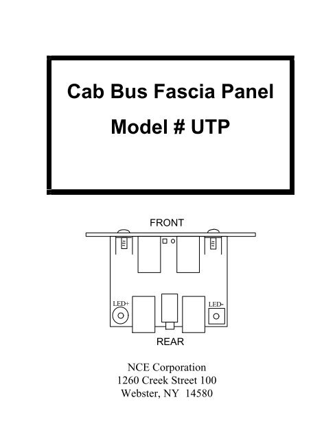
<strong>Cab</strong> <strong>Bus</strong> <strong>Fascia</strong> <strong>Panel</strong><br />
<strong>Model</strong> # <strong>UTP</strong><br />
FRONT<br />
LED+<br />
LED-<br />
REAR<br />
<strong>NCE</strong> Corporation<br />
1260 Creek Street 100<br />
Webster, NY 14580
The <strong>UTP</strong> cab bus panel provides a low cost means of adding walk<br />
around capability to your layout.<br />
The panel has 4 RJ-12 connectors wired in parallel, two on the<br />
front and two on the rear. Your cab bus can be “daisy chained”<br />
from one panel to the next using the rear connectors. One or two<br />
cabs can then be plugged in to the front connectors. Please note<br />
the “Command Station” side versus the “More <strong>UTP</strong> panels”<br />
side in Figure 1 when wiring your panels.<br />
From<br />
Command<br />
Station<br />
Figure 1 Connection of multiple <strong>UTP</strong>s<br />
To more<br />
<strong>UTP</strong><br />
<strong>Panel</strong>s<br />
PROPER CAB BUS CABLING<br />
The cables that connect the command station to the <strong>UTP</strong> and from<br />
<strong>UTP</strong> to <strong>UTP</strong> must be wired “straight through” meaning Pin 1 of<br />
one connector must be connected to Pin 1 of the other connector<br />
(see figure 2). Please note that this is not the normal telephone<br />
cable wiring.<br />
Proper orientation of the RJ-12 connectors on cab bus cables
Figure 2 Correct wiring of RJ-12 <strong>Cab</strong>le<br />
The normal wire gauge for RJ-12 cables is #28 or #26. This wire<br />
size is sufficient for cab bus lengths of up to about 30 or 40 feet<br />
(10-13 meters). If your layout requires a cab bus longer than this<br />
we suggest adding extra power to the bus at about 30 foot intervals.<br />
This is easily done by plugging a DC power supply in to the 1/8<br />
inch (3.5mm) plug on the back of the <strong>UTP</strong>. The tip of the plug is<br />
positive (+) and the sleeve is negative. We recommend a “wall<br />
wart” (the black box that hangs on your wall outlet) type supply in<br />
the range of 12 to 14 volts DC with a capability of ½ to 1 Amp.<br />
These supplies are easily found at Radio Shack .<br />
INSTALLING AN LED AS A TRACK STATUS LIGHT<br />
If you wish an LED can be installed between the two front RJ-12<br />
connectors on the panel to serve as a track status light. We<br />
recommend using a T1 sized (.100 inch diameter) bi-color LED.<br />
Solder the LED to the bottom of the PC board. Leave enough lead<br />
length to bend the LED over and fit it through the hole in the front<br />
panel. You will also need to solder a 1K ¼ watt resistor in the two<br />
holes marked “1K”. Connect the panel to the track using the two<br />
holes provided at the back of the PC board marked LED- and<br />
LED+. If you don’t want to solder wires to the panel the PC board
holes are sized to accept up to #4 screws. Ignore the polarity<br />
markings if using a bi-color LED.<br />
INSTALLING AN LED AS A PANEL LOCATOR LIGHT<br />
You may wish to install an LED on the <strong>UTP</strong> panel to help<br />
operators to find the panel darkened or dimly lit rooms.<br />
Conventional T1 sized red, green or yellow LED can be used.<br />
Solder the LED to the bottom of the PC board. Leave enough lead<br />
length to bend the LED over and insert it through the hole in the<br />
front panel. Be sure to solder the shorter lead (cathode) of the LED<br />
in to the square hole. You will also need to solder a 1K ¼ watt<br />
resistor in the two holes marked “1K”.<br />
Powering the panel locator LED from cab bus power<br />
If you wish to power the LED from the cab bus power, jumper a<br />
small wire from the hole marked “+” to the holes marked “LED+”.<br />
Similarly add a small jumper wire from the holes marked “LED-“<br />
to the hole next to the one marked “+”.<br />
Powering the panel locator LED from external power<br />
If you wish to power the LED from an external source connect the<br />
holes marked LED+ and LED- to the + and - terminals of a 5-15<br />
volt DC power supply.<br />
A front panel plate and two #6 screws for attaching it to the <strong>UTP</strong><br />
printed circuit board are supplied. Note that if you want the LED<br />
at the top of the panel you should install the <strong>UTP</strong> “upside down”.<br />
This will also keep dust from building on (and inside) the RJ-12<br />
connectors.