Quantum Revolution - DCC Concepts
Quantum Revolution - DCC Concepts
Quantum Revolution - DCC Concepts

You also want an ePaper? Increase the reach of your titles
YUMPU automatically turns print PDFs into web optimized ePapers that Google loves.
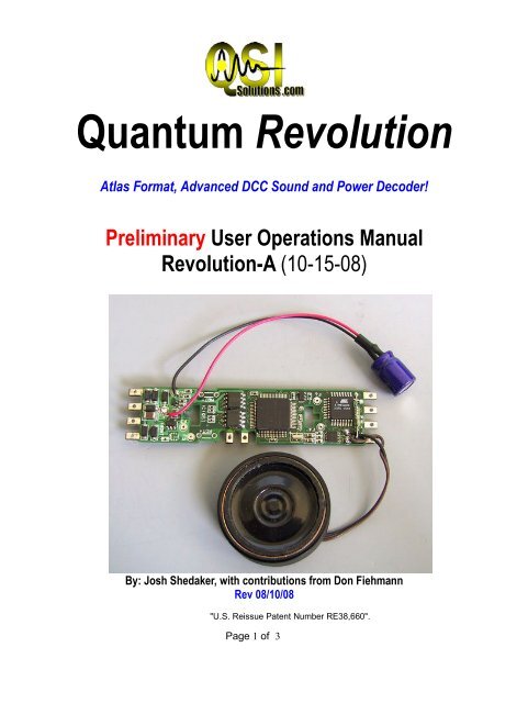
<strong>Quantum</strong> <strong>Revolution</strong><br />
Atlas Format, Advanced <strong>DCC</strong> Sound and Power Decoder!<br />
Preliminary User Operations Manual<br />
<strong>Revolution</strong>-A (10-15-08)<br />
By: Josh Shedaker, with contributions from Don Fiehmann<br />
Rev 08/10/08<br />
"U.S. Reissue Patent Number RE38,660".<br />
Page 1 of 3
<strong>Quantum</strong> <strong>Revolution</strong>-A User Operations Manual Table Of Contents<br />
1: Introduction; Viva La <strong>Revolution</strong>! PG: 3<br />
1A: <strong>Revolution</strong> features PG: 3<br />
1B: <strong>Revolution</strong> Specs. PG: 4<br />
2: Installation overview PG: 5<br />
2A: Preparing the locomotive PG: 5<br />
2B: Pre-Install Precautions (motor isolation, lighting resistors etc) PG: 6<br />
2C: Pre-Install Loco modifications (tender mods, weight removal etc) PG: 6<br />
2D: Installing and Wiring Your Decoder PG: 6<br />
3: Programming your new decoder PG: 9<br />
3A: Basic Operational CV's PG: 9<br />
3B: Analog Programming PG: 11<br />
3C: Individual volume Levels PG: 14<br />
4: <strong>Revolution</strong>ary Operations PG: 15<br />
4A: Functions and Features Explained PG: 15<br />
Sound of Power PG: 16<br />
Braking PG: 16<br />
Doppler Effect PG: 16<br />
Grade Crossing PG: 17<br />
Disconnect/Standby/Shutdown PG: 17<br />
5: Fine Tuning Your Performance PG: 18<br />
5A: BEMF Explained PG: 18<br />
5B: RTC Explained PG: 18<br />
5C: PID Explained PG: 18<br />
6: Customizing Sound Files Using the <strong>Quantum</strong> Programmer PG: 22<br />
6A Changing the software set PG: 22<br />
7: Special Operation and Troubleshooting PG: 22<br />
8: Using 1.5v, 15ma. Lamps and LEDS<br />
9: Configuring Light Ports on <strong>Quantum</strong> <strong>Revolution</strong>-A PG:29<br />
Page 2 of 3
1:Viva la <strong>Revolution</strong>!<br />
Congratulations; you are now the delighted owner of the <strong>Quantum</strong> <strong>Revolution</strong>, the most advanced sound<br />
decoder on this planet. With this decoder you will have access to 8-channel, high fidelity sound, as well<br />
as the most sophisticated motor drive and lighting effects ever combined into one unit. The addition of the<br />
<strong>Quantum</strong> Programmer (MSRP $99.95) makes the <strong>Revolution</strong> the most easily customized sound<br />
decoder available – period! Follow the procedures outlined in the following, and you'll soon discover that<br />
this decoder is simply, well… <strong>Revolution</strong>ary!<br />
For a long time, those of us in the model railroad “sound world” were stuck with whatever horn,<br />
whistle, air pump, chuff and bell the manufacturer decided was suitable. As a result, most of us at one<br />
time or another thought something like: "Well, I really like the exhaust sound, but man, that horn is<br />
terrible.” The QSI <strong>Revolution</strong> obsoletes ALL such limitations. Simply tell us what you want when you<br />
order your decoder, and we'll program it for you before we ship it! Further, with the <strong>Quantum</strong> Programmer,<br />
you can add or change whatever sounds (and more) you want, whenever you want. So read on – and join<br />
the <strong>Revolution</strong>!<br />
1a: <strong>Revolution</strong> Features and Specifications<br />
1: 8-Channel Sound – enabling multiple sounds to play at one time.<br />
2: 6 Lighting Outputs, with many programmable settings, including:<br />
Headlight/Tail Light<br />
Fire Box Flicker<br />
Front and Rear Mars Light<br />
Front and Rear Ditch Light<br />
Front and Rear Number Board Light<br />
Cab Light<br />
Exclusive: All lighting outputs support 256 intensity levels for “<strong>Revolution</strong>ary” brightness control!<br />
3: Motor Control RTC (Regulated Throttle Control/BEMF) – for supreme low - speed performance,<br />
smooth acceleration, braking, and incomparable power - sharing between locomotives in consists.<br />
(Have you ever dared to try and prototypically consist a helper at the rear of a train RTC makes it<br />
possible.)<br />
4: Load-responsive exhaust sounds.<br />
5: Verbal CV, speed and status reporting.<br />
6: Sound-of-Power (see section 4a for a full description of this feature) for even more control over<br />
exhaust sounds.<br />
7: Dual-mode operation – designed to run on DC or <strong>DCC</strong>.<br />
8: Advanced Analog: All sound features available in <strong>DCC</strong> are available in DC using<br />
the <strong>Quantum</strong> Engineer add-on controller (sold separately) to your DC power pack.<br />
9: All <strong>Quantum</strong> 2 products can be upgraded with new sounds and software from the QSI<br />
Solutions website using the <strong>Quantum</strong> Programmer (sold separately). This keeps your<br />
revolutionary sound system perpetually up-to-date with new features, improvements and sounds. You<br />
might say we’ve obsoleted obsolescence!<br />
10: Simple installation. Two distinct decoder formats means most locomotives will be easily<br />
adaptable to accept the following decoders:<br />
Page 3 of 3
<strong>Revolution</strong>-A: For all locomotives that have an Atlas or Kato style board, and<br />
<strong>Revolution</strong>-U: For standard wired-style decoders with an 8-pin NMRA plug and a 9-pin JST<br />
header.<br />
Automatic Features<br />
The following <strong>Quantum</strong> features are automatically controlled as a function of the directional state of the locomotive<br />
Feature Forward Neutral From Forward Reverse Neutral From Reverse<br />
Headlight Bright Dim Dim Dim<br />
Rear Tender Lt. Dim Dim Bright Dim<br />
Mars Light Strobing Steady On Steady On Steady On<br />
Ditch Lt. On Off Off Off<br />
Num. Board. Lt. On On On On<br />
Marker Lights On On On On<br />
Cab Lights Off After 10 On After 10 Secs. Off After 10 Secs On After 10 Secs.<br />
Secs.<br />
Steam Blower Off After 10 On After 10 Secs. Off After 10 secs. On After 10 Secs.<br />
Cylinder Cocks<br />
Vents & Cooling<br />
Fans<br />
Secs.<br />
If Armed, Plays<br />
16 times or<br />
until speeds<br />
greater than<br />
12 smph.<br />
Arms after 25 secs. If Armed, Plays 16<br />
times or until<br />
speeds greater<br />
than 12 smph.<br />
Arms after 25 Secs.<br />
Off On at random times Off On at random times<br />
1b: <strong>Quantum</strong> <strong>Revolution</strong> Specifications<br />
Dimensions: <strong>Revolution</strong>-A, 0.99” x 2.86”, <strong>Revolution</strong>-U, 2.13” x 0.69”<br />
Maximum Peak Voltage: 25v<br />
Steady State Current: 1.3 amp<br />
Stall Current (1 sec): 2+ Amps<br />
Speaker Load: 8/16 ohm or two, 8 ohm speakers in series (Not parallel)<br />
Caution: The speaker terminals are close together – use care to avoid a solder bridge between them when<br />
connecting the speaker wires!<br />
Audio Amplifier: Advanced D Style Format (2 watts)<br />
Light Outputs: 6 with 256 Intensity levels ea.<br />
Function Current: 100ma (A 220 Ohm on the circuit board resistor limits this current.)<br />
2: Installation Overview<br />
As model railroaders, we understand the need for instant gratification when we get a new locomotive or<br />
decoder. We ask you to defer this for a moment or two while we go over some installation specifics.<br />
These days, most manufacturers produce <strong>DCC</strong>-ready locomotives – meaning that <strong>DCC</strong> installation is<br />
oftentimes literally a snap (which is the case with the <strong>Revolution</strong> A)! However, before you highball on into<br />
your installation, there are a few things you should do beforehand that will make things a lot easier in the<br />
long run.<br />
Page 4 of 4
1: Read this ENTIRE manual! (We know – yuk!)<br />
2: Remember that decoders are static-sensitive devices. Always discharge any static electricity<br />
you may have built up by touching a grounded pipe or a piece of sheet metal before beginning<br />
your installation.<br />
.<br />
3: Make sure you have a clean, well lighted area consisting of a non-conductive surface on which<br />
to perform your installation.<br />
4: Never do installation work with power applied to the decoder. This can burn up the decoder. We<br />
all love engines that smoke – but this is the wrong way to get it!<br />
5: Never touch your speaker output leads together.<br />
6: Never touch your motor output leads together.<br />
7: Never exceed the designated output ratings specified in section 1B.<br />
8: Work carefully, take your time and have fun. (What may be frustrating tonight, probably won’t<br />
be tomorrow.)<br />
10Th: Read this ENTIRE manual! (Yuk, etc.)<br />
2a: Preparing your locomotive; pre-install precautions<br />
We've already covered a few of the things that you don't want to do when installing your decoder. Now<br />
let's look at some things you do want to do to get your locomotive ready to roll.<br />
1st: Isolate the motor. This is one of the most critical aspects of any <strong>DCC</strong> decoder installation,<br />
regardless of make or model. You MUST make sure your motor no longer receives ANY power directly<br />
from the track. In other words, if you can find pick-up wires going directly from one side of your<br />
wheels/trucks to the motor terminals, you'll want to disconnect them where they connect to the<br />
motor not from the trucks. Disconnecting them will keep the <strong>DCC</strong> from “backfeeding” into the<br />
decoder and burning it up (see Step 5 of Section 2 regarding “smoke”!).<br />
Note that on certain locomotives the motor draws power directly from 2 sides of a split frame, which the<br />
motor is enclosed inside. Isolating this type of motor can be more difficult, and can require insulation of<br />
the inner parts of the frame. If you have any doubt about the type of motor set-up you have, please<br />
contact QSI Solutions for clarification before proceeding with the installation.<br />
Most modern models already have the motor isolated. If the locomotive instructions say anything about it<br />
being “<strong>DCC</strong> Ready,” then your model already has the motor isolated.<br />
2nd: Trace your wires. By identifying which wire goes where, you'll make things a lot easier. We<br />
recommend you devise some method of marking the wires once you have them traced out. That way,<br />
when you want to reconnect that headlight, you won’t be left sitting there, looking at a bundle of wires,<br />
thinking uhhhhhhh.....<br />
Hint: On the <strong>Revolution</strong>-A, move ONE wire at a time from the circuit board to the new decoder.<br />
2b: Pre-Installation loco modifications<br />
Now that you've isolated your motor and traced your wires, it is time to figure out where to put that<br />
Page 5 of 5
speaker. In steam locomotives, this is often pretty easy since most tenders are reasonably open inside. In<br />
diesels, it tends to be a bit more difficult. We'll outline a couple ideas and let you decide.<br />
2c: Speaker Selection<br />
Since we've talked about where you're going to put the speaker, let's take a step back and talk about<br />
which speaker you're going to use. QSI offers a plethora of new speakers with varying frequency<br />
responses – which means you now have many options. We recommend you experiment, so that you can<br />
decide how much modification you’re willing to do to accommodate a particular speaker. Hint: Be sure to<br />
use some type of baffle (enclosure) with your speakers. You can either use one of the available speaker<br />
enclosures, or with appropriate “sealing,” the body shell itself. If you're unsure about what kind of speaker<br />
you're going to need, feel free to call QSI Solutions for recommendations.<br />
Next, make the final decision on where you'll put your speaker(s). Some locomotives have a cover on the<br />
fuel tank that, when removed, reveals a weight that can also be removed. This is actually one of the<br />
better configurations, because it accommodates the largest speaker. Other options include removing<br />
weight from the top of the frame and broadcasting the sound out, quite prototypically, through the exhaust<br />
fan grills. The last (and possibly most common) configuration is to remove any cab detailing and locate<br />
your speaker in the remaining open space.<br />
2d: Installing and Wiring Your Decoder<br />
If you've followed our instructions so far, you should already know what this section covers<br />
because you’ve already read the entire manual, right That being the case, you should also have<br />
accomplished the following:<br />
1: You've verified that your motor is isolated<br />
2: You've traced your wires so you know where they all go<br />
3: You've figured out a location for your speaker<br />
4: You've performed any modifications necessary to fit the selected speaker into said<br />
location<br />
Now, take a moment to study the diagram below, as it will be referred to often in the coming paragraphs.<br />
Okay, here comes the fun part. After grounding yourself (no more sleep-overs), orient your decoder so<br />
that it matches the diagram above in terms of direction. Next, locate the pick-up wires coming from the<br />
trucks (these may be the same wires that you disconnected from the motor tabs when you isolated the<br />
motor). These wires will be tied into the outer-most contacts on the ends of the decoder. The left rail pick-<br />
Page 6 of 6
up will be tied into the output marked TRK-L (you'll note there are two tabs marked TRK-L , either tab will<br />
work if you do not have individual rail pick-up on the front and rear trucks) the right rail pick-up will attach<br />
to TRK-R (again either/or will work if you don't have the provisions to do both).<br />
Next, locate the motor + and – tabs. Tie the lead from the + motor tab to the left (motor +) tab on the<br />
decoder, and the - motor tab to the right (motor -) tab.<br />
At this point the locomotive should run on address 3. You won’t have lights or sound yet, since we haven't<br />
hooked them up.<br />
Important! <strong>Quantum</strong> <strong>Revolution</strong> lighting wiring is unique – please read carefully!<br />
Now, let's get the lights working. …………..<br />
The <strong>Quantum</strong> <strong>Revolution</strong> has extremely flexible lighting outputs that support either 1.5 volt 15 ma<br />
incandescent lamps, or LEDs. This eliminates the need for larger incandescent lamps, which take<br />
more space and generate more heat, and are not currently supported by the <strong>Quantum</strong> <strong>Revolution</strong><br />
product. LEDs. (Note: the <strong>Revolution</strong> lighting outputs differ from those of most decoders. First, the “blue”<br />
wire provides +5 volts instead of rectified <strong>DCC</strong> voltage. Second, each lighting output has a 220 ohm<br />
resistor in series with the output transistor.) Look at the diagram above, and you'll notice circuit diagrams<br />
on the right and left-hand side of the page. Simply go from the FO-F (or, FO-R) to the tab immediately<br />
next to it (marked on the diagram as +5). This second tab serves as the common (same as the blue wire<br />
on most decoders). When using LEDs, be sure to wire the polarity correctly. Wire the anode of the LED to<br />
the +5, and the cathode to the light function output. No additional resistors are needed.<br />
Incandescent 1.5 volt lamps should be a low-current [15 ma] lamps. Okay, we're getting close to being<br />
done now. The last remaining step is to wire in the speaker. The square hole on the board (shown here<br />
as SP+) is the + terminal for the speaker, while the round hole (shown as SP -) is the – terminal. Connect<br />
these to the terminals on your speakers and install your speaker into the location you've prepared for it.<br />
(These outputs may be connected to either speaker terminal if they’re not marked.)<br />
Put the shell back on, and put your loco on the track. (If you have a program track, check to be sure there<br />
are no short circuits after the shell is installed.) The moment you issue any sort of command (be it<br />
applying DC track voltage or issuing a function command on your <strong>DCC</strong> system) you should hear your<br />
newly-equipped locomotive thunder to life. Congratulations! You've done it! That wasn't nearly as hard as<br />
you thought it was going to be was it<br />
Page 7 of 7
3: Programming Your New Decoder<br />
Now that you've got it installed, let's take a look at programming some of the CVs in your decoder.<br />
This section is primarily for <strong>DCC</strong> users – but you can also do it DC; it just requires some different steps. First we’ll<br />
cover <strong>DCC</strong> programming, then programming with a DC power pack.<br />
Factory reset. Activate Factory Default gives Voice Confirmation of RESET<br />
CV 49 = 128<br />
CV 50 = 255<br />
CV 56 = 113<br />
3a: Basic Operational CVs<br />
Programming of all CVs in this decoder is performed according to the instructions provided with your <strong>DCC</strong> system.<br />
It should be noted that due to the relatively high in-rush current required to run this decoder, most systems require<br />
it to be programmed on the main line (or in “Ops Mode”). If that’s a problem with your particular <strong>DCC</strong> system, you<br />
can purchase a program track booster called the PowerPax from Tony's Train Exchange that will remedy the<br />
problem.<br />
*NOTE: These CV's are grouped so that similar CV's are together<br />
CV# CV NAME DEFAULT RANGE<br />
1 Primary Address 3 1-127<br />
17 Extended Address Lower Byte 192 *<br />
18 Extended Address Upper Byte 0 *<br />
29 Configuration Data #1 6 0-55<br />
2 Vstart (start voltage) 8 0-255<br />
5 Vhigh (top speed) 1 0-255<br />
3 Acceleration Rate (momentum) 0 0-255<br />
4 Deceleration Rate (momentum) 0 0-255<br />
51 Master Volume 127 0-127<br />
52 Horn Volume 11 0-15<br />
*= Special Range; See Below<br />
Page 8 of 8
CVs Explained<br />
QSI CV#’s<br />
QSI uses several unique CV’s in their decoders. These have up to 3 parts.<br />
Example: CV 55.70.1<br />
1. 55 is the CV Number (think of this as a room in a house)<br />
2. 70 is the Primary Index (think of this as a closet in the room)<br />
3. 1 is the Secondary Index (think of this as a shelf in the closet)<br />
To set a QSI CV’s<br />
1. Set CV49 to the Primary index value<br />
2. Set CV50 to the Secondary Index value (If no Secondary Index is shown set CV 50 to<br />
0)<br />
3. Now set the CV# to whatever value gives you the feature desired.<br />
1 Primary Address: If you're going to use a short address (between 1 and 127) you can simply enter that<br />
address as the value of CV1<br />
17/18 Extended Address: CVs 17 and 18 are known as a “paired” CV, meaning that the two CVs<br />
together hold one piece of information. If your <strong>DCC</strong> system does not compute the values of CV17/18 for<br />
you, here is a way to compute the values, by using a different value in each CV to “build” the address you<br />
want. To determine the values that are placed into these CVs use the following equation.<br />
A. Start with the locomotive address and divide it by 256 Sample 4449 ÷ 256 =<br />
17.3789....<br />
B. Take the whole number (17) and add 192. Sample 17+192=209<br />
C. Program the value (209) in step B is into CV17.<br />
D. Multiply the whole number (17)from step A by 256. Sample 17 X 256 = 4352<br />
E. Subtract the locomotive address from the computed Sample 4449 4352= 97<br />
valueinstepD.<br />
F.Programthevalue(97)instepEisintoCV18.(Somesystemmayrequirea0tobeplaced<br />
in front of numbers less than 100. That would make the 97 a 097.)<br />
G. To activate 4 digit addressing a value of 32 (bit 5) needs to be added to CV-29.<br />
Wasn’t that fun Here’s a simpler way to determine these values.<br />
29 Configuration Data 1: CV29 controls 4 things at one time. First, it controls which speed table is accessible<br />
in the decoder (i.e., 14, or 28/128 speed steps). Second, it determines whether or not your locomotive will still<br />
run in analog mode (analog mode conv. ). Third, it tells the locomotive which direction is its “normal” travel<br />
direction. Lastly, it determines whether your loco will accept a 2 or 4 digit address. For the specific value to<br />
enter use the reference chart below.<br />
Page 9 of 9
3b: Analog Programming<br />
PART OF THE METHOD OF RESETING AND WORKING WITH THIS UNIT IS ANALOG MODE IS THROUGH A<br />
MAGNETIC REED SWITCH WHICH IS AN OPTIONAL PART. IF YOU FEEL YOU NEED THIS PART PLEASE<br />
NOTIFY YOUR DEALER.<br />
CV Value for CV29 Hex<br />
or Dec<br />
Speed Steps /<br />
Speed Table<br />
Analog Mode<br />
Conv<br />
Normal<br />
Direction of<br />
Trave l<br />
2or4<br />
Digit Addr<br />
x00 0 14 OFF Forward 2<br />
x01 1 14 OFF Reverse 2<br />
x02 2 28/128 OFF Forward 2<br />
x03 3 28/128 OFF Reverse 2<br />
x04 4 14 ON Forward 2<br />
x05 5 14 ON Reverse 2<br />
x06 6 28/128 ON Forward 2<br />
x07 7 28/128 ON Reverse 2<br />
x10 16 14 Speed Table OFF Forward 2<br />
x11 17 14 Speed Table OFF Reverse 2<br />
28/128 Speed<br />
x12 18 Table<br />
OFF Forward 2<br />
28/128 Speed<br />
x13 19 Table<br />
OFF Reverse 2<br />
x14 20 14 Speed Table ON Forward 2<br />
x15 21 14 Speed Table ON Reverse 2<br />
28/128 Speed<br />
x16 22 Table<br />
ON Forward 2<br />
28/128 Speed<br />
x17 23 Table<br />
ON Reverse 2<br />
x20 32 14 OFF Forward 4<br />
x21 33 14 OFF Reverse 4<br />
x22 34 28/128 OFF Forward 4<br />
x23 35 28/128 OFF Reverse 4<br />
x24 36 14 ON Forward 4<br />
x25 37 14 ON Reverse 4<br />
x26 38 28/128 ON Forward 4<br />
x27 39 28/128 ON Reverse 4<br />
x30 48 14 Speed Table OFF Forward 4<br />
x31 49 14 Speed Table OFF Reverse 4<br />
28/128 Speed<br />
x32 50 Table<br />
OFF Forward 4<br />
28/128 Speed<br />
x33 51 Table<br />
OFF Reverse 4<br />
x34 52 14 Speed Table ON Forward 4<br />
x35 53 14 Speed Table ON Reverse 4<br />
28/128 Speed<br />
x36 54 Table<br />
ON Forward 4<br />
28/128 Speed<br />
x37 55 Table<br />
ON Reverse 4<br />
Page 10 of 10
Your locomotive can be programmed using a standard power pack.<br />
All advanced operations are easily programmed using your standard HO power pack. After entering<br />
programming (described below), the various features are selected and operated by using the direction switch.<br />
Program<br />
Option<br />
#'s (POP's)<br />
Option Name<br />
(Default Value)<br />
Message When<br />
Entering Option<br />
Option Description<br />
1 System Volume<br />
(16, Max)<br />
2 Load<br />
(0, No Load)<br />
3 Helper<br />
(Normal)<br />
“Volume equals X”<br />
“Load equals X”<br />
“Helper Equals”<br />
“Normal”<br />
“Lead”<br />
“Mid”<br />
“End”<br />
“Pusher”<br />
4 Directional “Direction Equals<br />
(Normal)<br />
X”<br />
5-7 Reserved “Reserved”<br />
Sets System volume (17 level) where level 16 is<br />
max and level 0 is off.<br />
Selects the starting and stopping inertia for both Regulated<br />
Throttle Control (RTC) and<br />
Standard Throttle Control (STC). Level 0 (no load), Level 1-<br />
15, increasing Load with<br />
acceleration to full speed from 15 seconds to 210 seconds<br />
in RTC and from 3 seconds<br />
to 45 seconds in STC.<br />
Selects Normal, Lead, Mid, End, or Pusher Helper in<br />
consists.<br />
Normal Locomotive has all sounds and lights enabled.<br />
Lead locomotive has all sounds enabled and Reverse Light<br />
disabled.<br />
Mid Helper has Horn, Bell and all lights disabled11.<br />
End Helper has Horn, Bell and all lights disabled except<br />
Reverse Light.<br />
Pusher has Reverse Light on all the time as train warning<br />
light. Horn, Bell and all other<br />
lights are disabled.<br />
Selects if the features associated with the locomotive’s<br />
direction are “Normal” or“Reversed”.<br />
8 V-Start(8.5v) “V-Start Equals X” Sets track voltage at which locomotive will leave Neutral.<br />
(See Example below)<br />
9 V-Max (12v) “V-Max Equals X” Sets track voltage at which full track power is applied to motor.<br />
10 Throttle Mode<br />
(RTC)<br />
“Mode Equals X”<br />
Selects between Regulated Throttle Control (RTC)<br />
and Standard Throttle Control (STC)<br />
11 Programming<br />
Reset<br />
“Warning-about to<br />
reset”<br />
Selects between Regulated Throttle Control (RTC) and<br />
Standard Throttle Control (STC).<br />
12 About “Model Number” Each Quick or Slow Operation provides progressive<br />
information about <strong>Quantum</strong> Model Number, Software<br />
Version, and Software Release Date.<br />
Where “X” is the current value of the Program Option. Defaults are shown in parenthesis along with the option<br />
name; defaults for volume levels are listed on the Diesel Model Specification sheet included with your<br />
locomotive.<br />
Page 11 of 11
Entering Programming<br />
Use this simple sequence to enter Programming using the direction switch.<br />
1. Apply power and turn up the throttle to hear the sound system come on.<br />
2. Within five seconds of powering up, turn on the Bell with a Quick Flip-and-Back operation of the direction<br />
switch.<br />
3. Within three seconds of the Bell turning on, turn off the bell with a second Quick Flip-and Back operation.<br />
4. Within three seconds, turn the Bell back on again with a third Quick flip-and-back operation.<br />
NOTE: If you delay too long after power has been first applied, the opportunity to enter Programming<br />
will “time out,” and you will need to start again by shutting off, and reapplying track power.<br />
Once you perform the three bell operations after applying power, the bell will shut off automatically, you will<br />
hear “Enter Programming,” and the headlight and reverse light will flash alternately off and on.<br />
Scrolling through the Program Options<br />
After entering Programming, you will hear an announcement of the first Program Option, “Option 1 - System<br />
Volume”.<br />
To access other Program Options, simply flip the direction switch to the opposite position and leave it there.<br />
Listen as each option number is announced in order.<br />
When you hear the Option Number you want, flip the direction switch back and leave it there. After you stop at<br />
an option you will hear the option number and name announced. When you are scrolling through and stopping<br />
at Program Options, you are not making any changes. To make changes you must actually enter the<br />
Program Option.<br />
Note: If you accidentally go to a higher option number other than the one you wanted, simply turn the power<br />
off, re-enter Programming and start again.<br />
Once you reach the last Program Option, it the decoder will continue to announce the last option number.<br />
Entering a Program Option and Making Changes<br />
After the verbal announcement of a Program Option, you can enter that option by performing a Slow or Quick<br />
Flip-and-Back operation of the direction switch. Upon entering a Program Option, you will hear the present<br />
setting for that option. For unused Program Options, you will hear “Reserved”. For any volume option, you will<br />
hear “Volume equals X” (where “X” is its present volume setting). After a moment, you will hear the sound at its<br />
present volume<br />
.<br />
Note: It is easy to distinguish between doing a Quick and Slow operation. When you flip the direction switch<br />
to do a Slow operation, wait until you hear a low level “hiss” sound from the locomotive; then immediately flip<br />
the direction switch back. To do a Quick operation, make sure you flip the direction switch back before you<br />
hear the “hiss” sound.<br />
Note: Entering a Program Option does not change the settings for that option; it only provides information<br />
about its present value. After entering the Program Option, additional Slow or Quick flip-and-back operations<br />
will program new settings as described in the above table. For all level adjustments, a Quick operation will<br />
decrease one level, while a Slow operation will increase one level.<br />
Note: Since “System Volume” is the first Program Option, you can use Quick or Slow operations<br />
immediately after entering Programming to change the System Volume.<br />
Page 12 of 12
Moving on to Other Program Options or Exiting Programming<br />
Flip the direction switch at anytime to the opposite position, and leave it there. The <strong>Quantum</strong> System will first<br />
return to and announce the present Program Option, and then automatically advance on to higher options.Exit<br />
Programming anytime you want by turning the power off, and then back on again.<br />
Example 1: Setting Throttle Mode (Program Option # 10)<br />
Program Option #10 determines whether your locomotive uses Regulated Throttle Control (RTC) or Standard<br />
Throttle Control (STC).<br />
Enter Programming after powering up your locomotive by turning the Bell on, then off and then on as<br />
described above.<br />
After the “Enter Programming” and “Option One - System Volume” announcement of the first Program<br />
Option, flip the direction switch and leave it there. You will hear “Option 1, 2, 3 … etc.” Stop when you hear<br />
“one-zero” by moving the direction switch back. You will hear “Throttle Mode”.Use a Slow or Quick flip of the<br />
direction switch to enter this option. If the throttle mode is at its default value (RTC), you will hear “Mode<br />
equals Regulated;” otherwise, you will hear “Mode equals Standard.”Use a Slow or Quick flip of the direction<br />
switch to change the Throttle Mode. Repeated Slow or Quick operations will cause the throttle mode to<br />
alternate between its two possible values “Regulated” or “Standard”.<br />
Once you have selected the Throttle Mode you wish to use, turn the power off. When you power up again,<br />
your locomotive will be using the Throttle Mode that you have just selected.<br />
Example 2: Setting V-Start (Program Option # 8)<br />
This option determines the voltage (and throttle position) at which the locomotive will leave Neutral and begin<br />
moving.<br />
Enter Programming after powering up your locomotive by turning the Bell on, then off and then on - as<br />
described above.<br />
After the “Enter Programming” announcement followed by “Option One - System Volume” announcement for<br />
the first Program Option, flip the direction switch and leave it there. You will hear the announcement “Option 1,<br />
2, 3 … etc.”. Stop when you hear the number “8” by flipping the direction switch back. You will hear “V-Start”.<br />
Use a Slow or Quick flip of the direction switch to enter this option. You will hear “V-Start equals X” in<br />
which“X” is the track voltage value presently set for leaving Neutral.<br />
Use a Slow or Quick flip of the direction switch to activate this option. Hear the message “Set throttle to V-<br />
Start.” After three seconds, the voltage will be announced. If you move the throttle, the new track voltage value<br />
is announced a few seconds later. Once throttle is set, use a Slow or Quick flip of the direction switch to begin<br />
the V-Start voltage setting procedure. The locomotive will move at a slow speed and the bell will ring<br />
continuously for about 25 seconds, indicating the correct value is being calculated. If you chose a very low<br />
voltage setting, be patient. If the locomotive does not move during this procedure, return to the beginning of<br />
this option or start over and choose a slightly higher throttle setting. At the end of the process, the locomotive<br />
will stop moving and the Horn will blow, signifying the end of the operation, and you will hear the message “V-<br />
Start = X” where “X” is the new setting.<br />
To leave Programming, turn the throttle off, and then power up for normal locomotive operation. Or continue to<br />
the next option (V-Max) by moving the direction switch and waiting for the next Programming Option to be<br />
announced.<br />
Page 13 of 13
Example 3: Setting V-Max (Program Option # 9)<br />
V-Max is set in the same manner as V-Start except upon entering this Program Option, you will hear<br />
“Set throttle to V-Max” which is the throttle position at which you want full track voltage to be applied to the<br />
motor (usually about 80% of full throttle). Then do a Quick or Slow operation to start the V-Max setting<br />
procedure. Like V-Start, the bell will ring continuously until the voltage is set followed by a horn blast to<br />
indicate the procedure has been accomplished. Setting V-Max is much faster than V-Start!<br />
3C: Individual Sound Volume<br />
Thanks to it's 8 sound channels, the <strong>Quantum</strong> <strong>Revolution</strong><br />
allows for a great amount of user control over individual<br />
sound volume. The CVs to change these individual volumes<br />
are listed in the chart below:<br />
*= Turbine Models Only<br />
**= Non-Turbo Charged Models Only<br />
Changing Individual Sound Volumes (CV 52.X )<br />
CV Individual Sound Range<br />
52 Horn Volume 0-15<br />
52.8 Bell Volume 0-15<br />
52.1 Motor Volume 0-15<br />
52.13 Turbine Whoosh Vol.* 0-15<br />
52.14 Turbo Volume 0-15<br />
52.15 Turbine Whine Vol.* 0-15<br />
52.16 Air Pump Volume 0-15<br />
52.19 Cooling Fan Volume 0-15<br />
52.21 Long Air Let-Off Vol. 0-15<br />
52.22 Short Air Let-Off Vol. 0-15<br />
52.24 Brake Squeal Vol. 0-15<br />
52.26 Generator Volume** 0-15<br />
52.28 Dynamic Brake Vol. 0-15<br />
52.34 Coupler Volume 0-15<br />
52.37 Air Brakes Volume 0-15<br />
52.4 Alternate Horn Vol. 0-15<br />
X’ refers to the value in column 1 of the table, the Primary Index number that will be entered into CV 49.<br />
To change the volume of individual sounds listed in the table below do the following:<br />
Set CV 49 to the Primary Index for the individual sound from the table below.<br />
Enter Volume level in CV 52 as follows: “0” = No sound, “1 – 15” sets volume from the lowest level at “1” to<br />
the highest at “15”, with volume levels at 2db increments. Defaults are typically set to 11.<br />
Primary Index entered into CV 49<br />
Individual Sound<br />
0 Horn<br />
8 Bell<br />
10 Diesel Motor<br />
14 Turbo<br />
16 Air Pump<br />
19 Vents and Cooling Fans<br />
21 Long Air Let-off<br />
22 Short Air Let-off<br />
24 Squealing Brakes/Flanges<br />
28 Dynamic Brakes<br />
34 Coupler Sounds<br />
37 Air Brake Sounds<br />
Page 14 of 14
4: <strong>Revolution</strong>ary Operations<br />
We've covered all the particulars, now lets have some fun. Again, since this decoder is full featured in both DC<br />
and <strong>DCC</strong> we'll split this into two sections again. First the <strong>DCC</strong>:<br />
With your locomotive on the track, call up the address on your <strong>DCC</strong> hand-held (which will be address 3 if you<br />
haven't already changed it). Upon entering the address you should hear the locomotive hiss briefly followed by<br />
the sound of the prime mover starting up. Depending on your system , you may need to issue a function<br />
command to start it up. From here when you toggle function 0 (or push the headlight button) the lights will<br />
come on.<br />
Now, give the horn a toot and roll your throttle up. The loco will begin to accelerate according to any<br />
momentum programming you did earlier. As the locomotive accelerates listen to the notching, notice that just<br />
previous to the notch up you can hear the motor quiet down a bit before it ramps up through the notch. This<br />
will continue until you reach either top speed or (where applicable) the transition (essentially shifting gears)<br />
where you will hear another couple notches.<br />
Now let's slow down and pull into the station or freight yard. As you slow you'll hear the brakes engage and<br />
start squealing, when you reach stop you'll hear the cylinders bleed off the last bit of pressure with a quick<br />
hiss.<br />
With DC the process is essentially the same except in order to play the horn and the bell you'll need to throw<br />
the direction switch back and forth, not quite as much control but the fun is still there and more so than ever<br />
before).<br />
There is another DC sound control option we haven't discussed yet. Broadway Limited makes a product called<br />
the <strong>Quantum</strong> Engineer which is a sound control device connects directly to the two track output wires. It<br />
provides a 28 button interface with individual controls for all the sounds within the decoder, as well as buttons<br />
to apply and release the brakes. (If using the <strong>Quantum</strong> Engineer you should consult the manual for proper<br />
operation procedures). Like we said: the most advanced sound control on the planet!<br />
4a: Functions and Features Explained<br />
First we'll go through function by function and discuss the uses of each of the basic functions. Please keep in<br />
mind that the following applies exclusively to <strong>DCC</strong> users.<br />
F1: Toggles Bell On or Off<br />
F2: Toggles Horn On or Off (also toggles alternate horn after triggered using F11)<br />
F3: Plays Coupler sounds. The first time you push the button the couplers will clank as they join<br />
together. The Second time you push the button you'll hear the pressure release and the pins bang<br />
apart.<br />
F4: Toggles Cooling Fans On or Off<br />
F5: Toggles Dynamic Brakes On or Off<br />
F6: When in neutral plays start-up sounds. When moving in forward or reverse arms Doppler effects so<br />
that the next time the horn is blown it automatically Dopplers down.<br />
F7: In neutral plays long air let off. When in forward Or reverse plays the flange/brake squeal sound.<br />
F8: Mute.<br />
F9: In neutral puts loco in standby/disconnect mode. When moving activates the Sound Of Power<br />
Page 15 of 15
function, when sound of power is activated you'll hear the horn hoot once. As you throttle up the loco<br />
will sound as though it's under a very heavy load. Concisely, if you throttle down you'll hear the motor<br />
ramp down like it's coasting. Neither of these functions will effect speed until F9 is pressed again when<br />
you will hear a double whistle hoot or horn blast indicating that Sound Of Power has been turned off.<br />
F10: Status Report. In neutral the loco will read back the address and any mode that it may be in<br />
(e.g., standby/disconnect). When moving, F10 acts as a speedometer giving a verbal read back of the<br />
scale miles per hour.<br />
F11: Toggles between the primary and secondary horn. After pressing F11 once F2 will control the<br />
secondary horn normally.<br />
F12: Toggles extra light function on or off.<br />
The <strong>Quantum</strong> <strong>Revolution</strong> also allows for changes in the “mapping” of these functions. Mapping is the ability to<br />
change which button on your handheld controls what function.<br />
Sound of Power<br />
When a diesel locomotive starts to pull a heavy load, the engineer opens the throttle causing the engine to rev<br />
up before the train even starts moving. In steam engines the chuff gets louder as the engineer opens the<br />
throttle. As a train reaches its set speed, the sound level drops. When the throttle is cut back, the sound level<br />
cuts back. A diesel engine should drop to an idle. These are all possible with the Sound of Power feature.<br />
Sound of Power works by comparing the speed set by the <strong>DCC</strong> command to the speed of the locomotive. The<br />
greater the difference between the two, the higher the volume. Keeping that in mind, it should be noted that<br />
putting a value in the momentum CVs (CVs 3 and 4) will make the effect more pronounced.<br />
Checking out the Sound of Power<br />
First increase the throttle on your <strong>DCC</strong> system. When the desired speed is reached push F9 you will hear the<br />
horn blast once and the volume increase. As you adjust the throttle you'll notice the sound of the locomotive<br />
change dependent on the direction of throttle change. I.E. If you increase the throttle you'll hear the sound get<br />
louder like the locomotive is under a load, if you decrease the throttle you'll hear the locomotive quiet down<br />
and go to idle as if it's going down a hill and no longer struggling. When finished using this feature simply<br />
press F9 again and you'll hear a double horn blast and the locomotive will go to whatever speed step the<br />
throttle is set to when Sound Of Power was disengaged.<br />
Braking<br />
You can get even more control over speed by braking with F7. As the engine is coasting, with speed set to<br />
zero, F7 will act as a brake with the added sound of the brake squeal. When you press F7 you will also hear<br />
an air release. The longer you press, the faster the braking. This feature requires values to be set in CV3 and<br />
CV4. If you don't have momentum in the locomotive when you drop the throttle to 0 and your loco will stop<br />
immediately negating the usefulness of the brake. Set CV3 and CV4 to some value. We like CV4 set to half of<br />
CV3’s value. So for starters, try about 50 in CV3 and 25 in CV4. You can program this on the main or “Ops<br />
mode”. This adds to the fun of switching. Be sure and try the braking feature you’ll enjoy the challenge of<br />
running an engine more like the prototype.<br />
Page 16 of 16
The Doppler Effect<br />
Sound waves move at the speed of sound. As a train approaches its speed vs the speed of its sound causes<br />
its sound wave to compress, which in turn, causes the pitch of its sound to seemingly increase. When the<br />
engine passes by, the opposite happens and its sound waves are stretched and the pitch of its sound drops.<br />
The greater the speed, the greater the shift in sound frequencies as the engine passes by.<br />
Checking out the Doppler Feature<br />
Model locomotives do not move fast enough to create such a shift in sound frequency. To achieve this the<br />
Doppler feature needs to be triggered as the locomotive passes. There are two ways to trigger the Doppler<br />
feature. First, with the whistle blowing for longer than a second, quickly release the whistle/horn key and then<br />
reapply. This quick drop out of the whistle signal will trigger a drop in the sound frequency, simulating the<br />
Doppler effect.<br />
The second way is to use F6 key. F6 is used for startup when the engine is stopped, when the locomotive is<br />
moving F6 is used to trigger the Doppler effect. The change in sound is impressive as the engine passes -<br />
sounds like the real thing! The faster the speed, the more pronounced is the effect.<br />
Grade Crossing<br />
Engineers use specific signals on the horn/whistle to communicate various actions (forward, reverse all stop<br />
etc.) one of the universally recognized signals is the grade crossing, used whenever a train is approaching an<br />
active roadway. Several other decoder manufacturers have included this signal in the past. But all were fairly<br />
limited in realism because they lacked a method for changes in signal timing. QSI has remedied this by<br />
including a provision in the <strong>Quantum</strong> Upgrade software that provides very fine control of the timing. (If you do<br />
not own a <strong>Quantum</strong> Programmer see your local dealer.)<br />
Checking out the Grade Crossing<br />
Unlike other functions the grade crossing does not come set to a default function key. You'll have to change a<br />
couple CVs to use this fun effect. We recommend that you assign this to F6 because the doppler effect can be<br />
triggered using just the horn button. In order to assign the grade crossing to F6 set CV49 to a value of 8 and<br />
then change CV53 to 154. Now, while moving, you should be able to simply press F6 and hear the classic<br />
long, long, short, long. Horn/whistle signal.<br />
Now, go to your programmer and “fine tune” this fine tune!<br />
Disconnect/Standby/Shutdown<br />
Locomotive Shut Down has three distinct user-controllable stages. Each stage is entered by doublepressingtheF9key.<br />
Stage One: Disconnect<br />
To enter “Disconnect,” double-press the F9 key in Neutral (neutral=speed step 0). You will hear a long air<br />
Page 17 of 17
elease. The motor drive will be disabled. The <strong>DCC</strong> throttle can be opened or closed without the locomotive<br />
moving As the throttle is opened or closed, you will hear the motor rev up and down in response to the throttle.<br />
Note that all Function Keys are active in Disconnect.<br />
To exit Disconnect, either double-press the F6 Start Up key as described in the Start Up section, or doublepress<br />
the F9 key again to reach Standby, which is the second stage of the Shut Down mode.<br />
Note: In Disconnect, you can also turn the Dynamic Brakes on (see Dynamic Brakes below) to<br />
create Sound–of-Power as the throttle is opened and closed. Prototype engineers use dynamic brakes<br />
to load and test the motor generator’s output efficiency while the locomotive remains stationary,.<br />
Stage Two: Standby<br />
To enter “Standby,” double-press the F9 key while in Disconnect, and you will hear a long air release, followed<br />
by a distinctive “low idle” sound. The directional lighting and optional ditch lights or mars light will also shut<br />
down.<br />
Note: In Standby, the motor will remain disconnected, while the air pumps, automatic cooling fans, number<br />
board lights and cab lights will continue to operate. Also in Standby, the locomotive will not<br />
respond to throttle or function keys with the following exceptions: The F6 Start Up Key, the F8 Mute Key<br />
(described below) and the F10 Status Key (also described below).<br />
To exit Standby, either double-press the F6 Start Up Key (as described in the Start Up section), or doublepress<br />
the F9 key again to access Total Shut Down, the final stage of Shut Down.<br />
Note: Standby is ideal for leaving your locomotive running on a siding. In addition to hearing the sound of the<br />
diesel at low idle, the locomotive will not respond to accidental changes in throttle settings or function keys.<br />
Stage Three: Total Shut Down<br />
Total Shut Down allows you to take the locomotive “off line” (turn off sounds and<br />
lights, ignore throttle settings and function commands) independent of the operating session. Note that the<br />
locomotive will still be “off-line” when power is next reapplied, regardless of whether the next session is<br />
analog (conventional DC), or <strong>DCC</strong>.<br />
Double press the F9 in Standby to enter Total Shut Down. You will hear a Long Air Let-off. The Air Pumps will<br />
turn off, followed by the Number Boards (if so equipped) and the sounds of the Cooling Fans shutting off, the<br />
louvers closing, the Diesel Motor shutting down and finally, the Cab Lights (if so equipped) turning off. A few<br />
seconds later you will hear the engineer’s door open and then shut.<br />
Note: In Total Shut Down, the locomotive will not respond to the throttle – nor will it respond to function keys<br />
except for the F6 Start Up Key (described below) and the F10 Status Key (also described below).<br />
To exit Total Shut Down, double-press the F6 key.<br />
Note: If power is turned off at any stage of Shut Down (Disconnect, Standby or Total Shut Down) or during a<br />
Shut Down procedure, the locomotive will remember the last Shut Down stage it was at during power down,<br />
and the locomotive will power up in the same stage.<br />
However, if Start Up is initiated during any of the above Shut Down procedures, the Shut Down is aborted,<br />
and the locomotive will return to normal operation.<br />
Start Up<br />
You can return your <strong>Quantum</strong> <strong>Revolution</strong>-equipped diesel locomotive to normal operation during any<br />
stage of Shut Down by double-pressing the F6 key. Start Up will be different for each stage of Shut<br />
Page 18 of 18
Down, but enter normal each will start up with a long air release, and will operation.<br />
Start Up from Disconnect: Double-press the F6 key in Disconnect, and the diesel locomotive will<br />
produce a long air release, the dynamic brakes will shut off and the locomotive will enter<br />
normal operation.<br />
Start Up from Standby: Double-press the F6 key in Standby, and your diesel will produce a long air<br />
release, directional lighting will turn on, the diesel motor sound will change from special low Idle to<br />
regular Idle, and the locomotive will enter normal operation.<br />
Start Up from Total Shut Down:<br />
Double-press the F6 key in Total Shut Down, and the locomotive will produce a long air release, you will hear<br />
the cab door opening and closing, and if so equipped, you’ll see the cab lights and number boards come on<br />
and the directional lighting turn on (if it was on previously). These actions are followed by the sounds of vents<br />
opening, the diesel motor starting up, the air pumps starting up and the locomotive’s entering normal<br />
operation.<br />
Note: During the Start Up procedure, no <strong>DCC</strong> function keys are active. However, in the event if the<br />
throttle is advanced beyond zero during any of the above Start Up procedures, the Start Up procedure will<br />
abort and the locomotive will enter normal operation.<br />
5: Fine Tuning Your Performance<br />
The <strong>Revolution</strong> offers many ways to fine-tune your locomotive for truly revolutionary motor response. This is<br />
accomplished through Regulated Throttle Control, Back EMF and what are referred to in the <strong>DCC</strong> industry as<br />
PIDs. The next section explains what each of these do, and how to use them to really tune your locomotive for<br />
prototypical operation.<br />
5a: Back EMF (Back Electro-Motive Force) Explained<br />
One of the better ways to explain BEMF is to compare it to the way an electric motor functions. For example, if<br />
you apply power to a motor, the shaft turns. Conversely, if you turn the motor shaft, the motor will generate<br />
power, or in our case, produce a voltage. Similarly, when a decoder applies power to a motor, it begins to<br />
rotate. However, the decoder applies power in pulses. As a result, there is a time between pulses when no<br />
voltage is applied to the motor. During this time the decoder can “read” the voltage produced by the motor. If<br />
the motor slows, the BEMF voltage drops, if speed increases, the voltage also increases. This is how a BEMF<br />
decoder can determine the speed of the motor, sense any change in motor speed, and respond accordingly to<br />
provide realistic load-related variations in speed as trains ascend and descend grades, for example.<br />
5b: Regulated Throttle Control (RTC) Explained<br />
Regulated Throttle Control (RTC) adds realistic momentum to your train operations. Although it has been<br />
available in analog from QSI, it has not been available in <strong>DCC</strong> until now. RTC uses Back EMF to simulate the<br />
massive inertial characteristics of prototype operations. An RTC-controlled locomotive will move through such<br />
“obstacles” as tight turnouts, raised track joints, etc., with little change in speed – and will easily maintain<br />
speeds of less than 1 scale mile per hour! However, if the locomotive encounters a long uphill grade, it will<br />
slowly reduce speed just as does the prototype. Similarly, when a downhill grade is encountered, it will slowly<br />
increase in speed like the prototype.<br />
Unlike Speed Control, which is a feature used by many older decoders. RTC is a true, comprehensive throttle<br />
control system, and is controlled by the same CV's that control speed curves, including (CV2, CV3, CV4, CV5,<br />
CV23 and CV24, and all CVs related to the speed curve.<br />
Page 19 of 19
The best news: since RTC-controlled locos slowly adjust their speed based on load, locomotives in consists<br />
tend to share power equally. This makes advanced (and truly prototypical) consisting extremely easy since the<br />
locomotives can actually “talk” to each other. Put that helper in the middle of the train, or that pusher at the end<br />
– where they belong!<br />
5c: PID (Proportional Integral Derivative) Control Explained<br />
The PID control process is a little like a three ring circus. Each of its three components play a part in the control<br />
process. To oversimplify, think of PID as a black box with the output as the power to the motor and the input as the<br />
BACK-EMF from the motor.<br />
We “tune” for smoothest operation by changing the CV values associated with PID parameters. But first, a little more<br />
tech-talk:<br />
The PID control processTo get a picture of how the PID process works, first consider that speed needs to be<br />
controlled. To do this, we send a speed-setting command to the decoder. This speed-setting command initiates the PID<br />
process and is called the “set point.” In response, our decoder sends power to the motor, which starts to turn. At the<br />
same time, the decoder reads the Back-EMF signal to determine how fast the motor is turning. Once the motor nears<br />
the speed of the set point, the PID process begins to function. The manner in which the individual PID components<br />
Page 20 of 20
interact is briefly described below. The Proportional component: The “P” part of the process stands for “Proportional,”<br />
which in essence, establishes a “speed band” parameter around our set point. This “proportional band”<br />
tolerates some speeds above and below the speed entered as the set point. It is somewhat akin to the way a<br />
thermostat controls furnace temperature in a house. The furnace continues to produce heat until its “set point”<br />
(thermostat setting) is reached. After this, some heat production (called overshoot) continues even after the<br />
thermostat turns the furnace off. Most thermostats then wait until the temperature drops about 2 degrees<br />
below the set point (called undershoot) before the furnace is again turned on. Its “proportional band” is<br />
between the two levels. The proportional component in PID works in a similar manner. The Integral<br />
component: The “I” part of the process stands for “Integral” action, which controls the difference between the<br />
set point and the center of the proportional band. This may not be the same due to system imbalance. The<br />
Integral action senses and tries to correct the difference between the set point and the decoder’s “center<br />
point.” The Derivative component: The “D” part of the process is “Derivative” action, which looks for any<br />
change in motor speed. When it senses a change, this function tries to correct it. Such a change could be<br />
triggered by a locomotive starting up a grade with a string of cars whose increased load has caused the motor<br />
to slow. The derivative component “sees” this change and applies a correction. Such a slow-down could also<br />
be caused by a bind in the mechanism or a tight spot in the track. Note that some decoders use only the P and<br />
I (PI) functions and not the D. The <strong>Revolution</strong>, on the other hand, is weighted toward utilization of the P and D<br />
components. Most of the decoders that use PID utilize a single set of values for the functions that are used<br />
over the total speed range. The <strong>Revolution</strong>, on the other hand, has four sets of PID values, between which it<br />
alternates depending on speed-step settings.<br />
PID and locomotive control (QUANTUM PROGRAMMER REQUIRED)<br />
Note that the only way we have of checking the effects of any PID modifications – for which the <strong>Quantum</strong><br />
Programmer is required – is by observing the reaction of the locomotive following each adjustment. There is<br />
no “standard” for the values used in these CVs, nor is there a standard way to set the CVs. For the most part,<br />
determining their optimum values is a matter of trial and error. Fortunately, the <strong>Revolution</strong> comes with a fairly<br />
universal PID structure.<br />
Setting CV Values (<strong>Quantum</strong> Programmer required)<br />
For best results, use “service mode” within the CV Manager software to change these CVs. Doing so makes it<br />
much easier to immediately see your results. Note that if the value in any of the (motor control) CVs is set<br />
too low, the locomotive will be “under-corrected.” If set too high (over-corrected), your prime-mover may react<br />
jerkily to speed changes. To tune a CV, keep increasing its value until the locomotive’s reaction becomes<br />
unstable or jerky. Then change the CV setting back to the value that was stable. A procedure like this is used<br />
to set the CVs used for motor control and only motor control.<br />
NOTE: We do not list the CV's required to change these parameters because they are absolutely locomotivespecific.<br />
If you are interested in changing these parameters you should purchase a <strong>Quantum</strong> Programmer and<br />
consult the included CV Manager software manual for more specific information.<br />
Page 21 of 21
6: Customizing Sounds Using The <strong>Quantum</strong> Programmer<br />
One of the primary advantages of the <strong>Quantum</strong> <strong>Revolution</strong> is its ease of customization. Using the <strong>Quantum</strong><br />
Programmer (sold separately) you can change the individual volumes and characteristics of all sounds with<br />
ease. We’ll cover the two most important parts of it here.<br />
6a: Changing The Software Set<br />
Using the Q2 Upgrade software, you can make any locomotive sound like any other locomotive. In fact you<br />
can easily put a RS-2 sound into a 4-8-4 Steam Locomotive! While ridiculous, this shows how flexible your<br />
new decoder is! This is also a big part of what makes this decoder truly revolutionary. Since you can infinitely<br />
upgrade the software, if down the road we come up with a new sound that you can't live without, all you need<br />
do is download it from the internet, and program it into your locomotive with the <strong>Quantum</strong> Programmer.Your<br />
locomotives need never again be out of date. As we said, we’ve tried to make obsolescence obsolete!<br />
7: Special Operation and Troubleshooting<br />
For most complete information, see the “Troubleshooting” sections (listings) in the <strong>Quantum</strong> <strong>DCC</strong> Reference<br />
Manual (Ver. 4) and <strong>Quantum</strong> Analog Reference Manual (Ver. 4) at http://www.qsisolutions.com.<br />
PART OF THE METHOD OF RESETING AND WORKING WITH THIS UNIT IN ANALOG MODE IS THROUGH A<br />
MAGNETIC REED SWITCH WHICH IS AN OPTIONAL PART. IF YOU FEEL YOU NEED THIS PART PLEASE<br />
NOTIFY YOUR DEALER.<br />
<strong>DCC</strong> Program Track Operation<br />
Your locomotive conforms to NMRA standards for program track operation. However, the <strong>Quantum</strong> System<br />
requires more current to operate than standard <strong>DCC</strong> decoders and may not respond to the limited program<br />
track power from some <strong>DCC</strong> command stations. If you are unable to program in Service Mode on your<br />
program track, all CV’s in your <strong>Revolution</strong>-equipped locomotive can be programmed in Ops Mode. Note also<br />
that Tony’s Train Exchange® offers a simple, inexpensive power booster (PowerPax by <strong>DCC</strong> Specialties)<br />
that will once again enable you to program on the program track with any <strong>DCC</strong> command station.<br />
Manual Controls<br />
There is an optional reed switch which is used to control sound volume or reset the locomotive to factory<br />
default values. If you desire this part please contact your dealer.<br />
To adjust the volume by hand: (Analog and <strong>DCC</strong>)<br />
Note: Volume can also be adjusted digitally using the programming methods described in the programming<br />
sections of this manual. However, if you turn the volume down using the Manual Volume Control, you will not<br />
be able to increase the volume using programming above the level set by the reed switch.<br />
Using Magnetic Reed Switches: TheReedSwitchisnotinstalledonthe<strong>Revolution</strong>-A<br />
Locate the reed switch on the decoder.<br />
Power up the locomotive and leave in Neutral.<br />
Page 22 of 22
Place the enclosed Magnetic Wand over the reed switch on the decoder and wait as you hear the volume<br />
increase or decrease in incremental amounts as the Horn hoots about every second. Move the wand away<br />
and again place it over the reed switch to change the direction (louder or softer) of the volume. Remove the<br />
wand when you reach<br />
the desired volume level<br />
Note: System Volume can also be adjusted digitally using the programming methods described in the Analog<br />
and <strong>DCC</strong> programming sections of this manual.<br />
To Reset Your Locomotive to Factory Default Values (Analog and <strong>DCC</strong>)<br />
In the event your locomotive’s sound and control system misbehaves – and turning the power off and back on<br />
does not return it to normal operation – you can reset your locomotive to original factory values.<br />
Locomotives with Magnetic Reed Switches<br />
Locate the reed switch on the decoder.<br />
Turn off the power.<br />
Place the Magnetic Wand over the reed switch area, apply power and leave the wand in place there until you<br />
hear the word “Reset”. Your locomotive is now reset to original factory defaults including all <strong>DCC</strong> and Analog<br />
values<br />
.<br />
High Voltage Circuit Breaker (Analog and <strong>DCC</strong>)<br />
Your <strong>Revolution</strong> equipped locomotive is designed to operate on the normal HO track voltage supplied by most<br />
HO power packs. If track voltage gets too high, the motor drive circuit will automatically shut down and the<br />
locomotive will coast to a stop. The <strong>Quantum</strong> System will alert you to the problem through a continuous series<br />
of Horn blasts. This built-in safety feature protects <strong>Quantum</strong> <strong>Revolution</strong> electronics and the electric motor from<br />
excessive voltage.<br />
To restart your locomotive, reduce the track voltage until the horn blasts stop and the motor re-engages.<br />
Note: Later <strong>Quantum</strong>-equipped locomotives use a different motor control design, which will operate at higher<br />
voltage.<br />
Reasons why your locomotive is silent or will not start (Analog and <strong>DCC</strong>)<br />
In the event your locomotive remains silent after power up, and turning the power off and back on does not<br />
return it to normal operation, try the following suggestions to bring your locomotive back to normal sound<br />
operation.<br />
1. Make sure the locomotive has not been Muted with the <strong>DCC</strong> F8 key or <strong>Quantum</strong> Engineer Mute Key.<br />
2. Check to see if your Manual Volume Control or Programmed Digital Volume has been turned all the way<br />
down.<br />
3. You may have shut down your locomotive in <strong>DCC</strong> using the F9 key, or in Analog using the <strong>Quantum</strong><br />
Engineer Shut Down key. Use the F6 key in <strong>DCC</strong>, or the <strong>Quantum</strong> Engineer Start Up key or Magnetic Wand in<br />
Analog, which both selects and starts the locomotive.<br />
Important: The Magnetic Wand will not start your locomotive in <strong>DCC</strong> if it is in a “Shut Down” state (mode). To<br />
start in <strong>DCC</strong>, you must first select the locomotive with its ID number and then use (double-press) the F6 key.<br />
Note also that it will take a couple of seconds after you double press the F6 key before you will hear the pump<br />
sounds start.<br />
Note: It makes no difference whether you start your locomotive in <strong>DCC</strong> or DC. Once started, you can return to<br />
either DC or <strong>DCC</strong> operation.<br />
Page 23 of 23
If the above methods do not start your locomotive, use the magnetic wand to reset your locomotive to factory<br />
default values as described above.<br />
Using 1.5v, 15ma. Lamps and LEDS for the <strong>Quantum</strong> <strong>Revolution</strong>-A<br />
Options<br />
The <strong>Quantum</strong> <strong>Revolution</strong>-A has 6 lighting outputs that can directly operate 1.5v,<br />
15ma bulbs and LEDS without the need for external dropping resistors.<br />
There are 6, 200 ohm chip resistors (221) on the bd that control the outputs. See<br />
Photos Below<br />
Since there is considerable difference in the performance between the various<br />
manufactures bulbs, the 1.5v bulbs may not provide the proper intensity for all<br />
applications.<br />
If your 1.5v bulbs are appearing DIM then you can change the chip resistors on the<br />
bd from 200 ohms to 180 ohms.<br />
We have these in stock if you need them, just call and we will send at no charge.<br />
Also, if you need to have two 1.5v, 15 ma bulbs illuminated from a single output like<br />
for loco’s that have 2 lamp headlights, you would have to change the resistors to<br />
130 ohms and wire the bulbs in series.<br />
We have these in stock if you need them, just call and we will send at no charge.<br />
Tools and Procedures<br />
Your normal soldering tools can be used to remove and install the chip resistors.<br />
1) Flux the chip resistor you are going to remove.<br />
2) Apply the tip of your soldering iron directly to the chip to heat up.<br />
3) The solder will start to re-flow and you can remove the chip with a forceps.<br />
4) Reflux the chip pads and the chip and add a little solder to the chip pads.<br />
5) Then place the chip on the pads and add heat to re-flow the solder.<br />
Since these are chip resistors polarity in not an issue.<br />
Page 24 of 24
Page 25 of 25
Page 26 of 26
Configuring Light Ports on <strong>Quantum</strong> <strong>Revolution</strong>-A<br />
The <strong>Quantum</strong> <strong>Revolution</strong>-A sound decoder has 6 Light ports or outputs. These are<br />
numbered 1-6 and must be configured for the following features using Q2Upgrade<br />
and then downloading the configured firmware to the locomotive using the <strong>Quantum</strong><br />
Programmer. Default Diesel settings (after 7-28-08) are shone below.<br />
Ports 1 and 2 are reserved for the Front and Rear Headlights. Ports 3 – 6canbe<br />
configured for any other feature. Note that each port can only have one feature<br />
assigned to it and can only be changed using Q2Upgrade and then downloading the<br />
configured firmware to the locomotive using the <strong>Quantum</strong> Programmer. (Sold<br />
Separately).<br />
Light Output Settings CV’s<br />
(consult the user’s manual for your <strong>DCC</strong> system on Programming CV’s)<br />
QSI CV#’s<br />
QSI uses several unique CV’s in their decoders. These have up to 3 parts.<br />
Example: CV 55.70.1<br />
55 is the CV Number (think of this as a room in a house)<br />
.70 is the Primary Index (think of this as a closet in the room)<br />
.1 is the Secondary Index (think of this as a shelf in the closet)<br />
Page 27 of 27
To set a QSI CV’s<br />
1. Set CV49 to the Primary index value<br />
2. Set CV50 to the Secondary Index value (If no Secondary Index is shown set<br />
CV 50 to 0)<br />
3. Now set the CV# to whatever value gives you the feature desired.<br />
Common CV’s to modify Light Outputs on QSI <strong>Revolution</strong>-A<br />
(Cheat Sheet)<br />
Front Headlight (Port 1)<br />
CV 55.70.0 Initial State<br />
1 = Automatic Control<br />
2=ON<br />
3=Dim<br />
CV 55.70.1 Automatic Configuration<br />
86 = Bright in FWD, Dim in NFF, DIM in REV, Dim in NFR<br />
2=Bright in FWD, OFF in NFF, OFF in REV, OFF in NFR<br />
Rear Headlight (Port 2)<br />
CV 55.73.0 Initial State<br />
1 = Automatic Control<br />
2=ON<br />
3=Dim<br />
Example: CV 55.70.1<br />
1) Set CV 49 to<br />
70<br />
2) Set CV 50 to 1<br />
3) Set CV 55 to 6<br />
This will make the Front<br />
Headlight Bright when<br />
the loco is moving<br />
Forward, Dim when it is<br />
moving Forward and<br />
stops, Off in Reverse,<br />
and OFF when it is<br />
going in reverse and<br />
comes to a stop.<br />
CV 55.73.1 Automatic Configuration<br />
101 = Bright in REV, Dim in NFR, Dim, FWD, Dim in NFF<br />
32 = Bright in REV, OFF in NFR, OFF in FWD, OFF in NFF<br />
Front Ditch Lights (Port 3 – Left, Port 4 – Right) Both work together.<br />
CV 55.84.0 Initial State<br />
1 = Automatic Control<br />
2=ON<br />
3=Dim<br />
Page 28 of 28
CV 55.84.1 Automatic FWD<br />
0=OFF<br />
1=Dim<br />
2 = Bright<br />
3 = Strobe<br />
4 = OFF (Strobe with horn)<br />
5 = Dim (Strobe with horn)<br />
6 = Bright (Strobe with horn)<br />
CV 55.84.2 Neutral From FWD<br />
0=OFF<br />
1=Dim<br />
2 = Bright<br />
3 = Strobe<br />
4 = OFF (Strobe with horn)<br />
5 = Dim (Strobe with horn)<br />
6 = Bright (Strobe with horn)<br />
CV 55.84.3 Automatic REV<br />
0=OFF<br />
1=Dim<br />
2=Bright<br />
3 = Strobe<br />
4 = OFF (Strobe with horn)<br />
5 = Dim (Strobe with horn)<br />
6 = Bright (Strobe with horn)<br />
CV 55.84.4 Neutral From REV<br />
0=OFF<br />
1=Dim<br />
2 = Bright<br />
3 = Strobe<br />
4 = OFF (Strobe with horn)<br />
5 = Dim (Strobe with horn)<br />
6 = Bright (Strobe with horn)<br />
Mars Light (Port 5)<br />
CV 55.76.0 Initial State<br />
1 = Automatic Control<br />
2=ON<br />
3=Dim<br />
Page 29 of 29
CV 55.76.1 Automatic FWD<br />
0=OFF<br />
1=Dim<br />
2 = Bright<br />
3 = Strobe<br />
CV 55.76.2 Automatic Neutral From FWD<br />
0=OFF<br />
1=Dim<br />
2 = Bright<br />
3 = Strobe<br />
CV 55.76.3 Automatic REV<br />
0=OFF<br />
1=Dim<br />
2 = Bright<br />
3 = Strobe<br />
CV 55.76.4 Automatic Neutral From REV<br />
0=OFF<br />
1=Dim<br />
2 = Bright<br />
3 = Strobe<br />
CV 55.92.0 Initial State<br />
0=OFF<br />
2 = Blinking Light<br />
18 = Rotating Beacon<br />
34 = Strobe Light<br />
Overhead Beacon (Port 6) Works with F12 button<br />
For More Options see NMRA reference Manual for QSI Quatum Q1a and Q2<br />
Equipped Locomotives.<br />
http://qsisolutions.com/pdf/quantumdccrefmanual_4_3_0.pdf<br />
Page 30 of 30
Most importantly, thank you for choosing the <strong>Quantum</strong> <strong>Revolution</strong>. To realize its full potential, we<br />
strongly recommend you purchase the <strong>Quantum</strong> Programmer, and gain access to the everexpanding<br />
sound and control possibilities the <strong>Revolution</strong> offers. And of course, for additional<br />
information and technical support, please feel free to contact us at any time.<br />
Good railroading!<br />
Josh Shedaker<br />
Special thanks to Don Fiehmann, QSI and Budd Shedaker for their contributions and editting.<br />
<strong>Quantum</strong> <strong>Revolution</strong> complete <strong>DCC</strong> Reference Manual:<br />
http://qsisolutions.com/pdf/quantumdccrefmanual_4_3_0.pdf<br />
Notes:<br />
(10-15-08)<br />
The Katos require the new revision of download files from QSI with the revise PID parameters,<br />
1050-0v7-25-3 that supports the new PID and allows changing the PID. Otherwise, they have midspeed<br />
surging.<br />
Page 31 of 31
Software ID<br />
Diesel Steam Other<br />
<strong>Quantum</strong> <strong>Revolution</strong>-A<br />
Advanced <strong>DCC</strong> Sound and Power Decoder, Atlas Format<br />
Advanced, Co-Processor Technology, 32 Bits, 8 Channels.<br />
Low Power design that allows mounting almost anywhere.<br />
<br />
<br />
Higher Audio output for Software crisp, clear, ID high fidelity sounds.<br />
Additional memory providesDiesel for more Steam sounds andOther<br />
control<br />
Better Motor Performance under marginal power.<br />
Super, Smooth low/mid speed performance under RTC.<br />
Steam versions of the board also support a chuff CAM.<br />
Lighting: 6 light outputs, all with 256 intensity levels<br />
User<br />
<strong>Quantum</strong><br />
Calibration of BEMF<br />
<strong>Revolution</strong>-A<br />
vs. Scale MPH for Scale MPH<br />
Advanced readouts. <strong>DCC</strong> Sound and Power Decoder, Atlas Format<br />
User Calibration of Chuff rate for low range speeds.<br />
User Configurable Brakes and Grade Crossing sounds.<br />
Magnetic Wand for volume control/reset or by programming.<br />
Doppler Effect by key control of horn/whistle function.<br />
Programmable Grade Crossing Effect!<br />
Sound of Power by Throttle Control and loading effects.<br />
Complete Sound file downloading Supports Cut & Paste or<br />
editing of sound records: Horn/Whistle, Alternate Horn/Whistle,<br />
Bell, Diesel Motor, Chuff, Dynamic Brakes, Fans, Steam<br />
Generator, Pump, Cooling Fan/Vents.<br />
Compatible with all <strong>DCC</strong> Systems.<br />
The Magnetic Reed Switch is not installed on this unit.<br />
Caution: The speaker terminals are close together.<br />
Please use care to avoid a solder bridge between them when soldering!<br />
Maximum Peak Voltage: 25v<br />
Steady State Current: 1.3 Amp<br />
Stall Current: (1 sec): 2+ Amps<br />
Speaker Load: 8/16 ohm or 2, 8 ohm in Parallel<br />
Audio Amplifier: Advanced D Style Format 2 Watts<br />
Guaranty: This Decoder is Unconditionally Guaranteed for 2 yrs.<br />
QSI Solutions c/o American Hobby Distributors, 57 River<br />
Road, Suite 1023, Essex Junction, VT 05452, Toll-free<br />
(800) 671-0641 Fax 802-878-5550, e-mail<br />
info@qsisolutions.com<br />
Page 32 of 32