BIO, BIOA, ZIO - Combustion 911
BIO, BIOA, ZIO - Combustion 911
BIO, BIOA, ZIO - Combustion 911

Create successful ePaper yourself
Turn your PDF publications into a flip-book with our unique Google optimized e-Paper software.
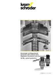
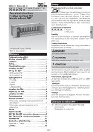
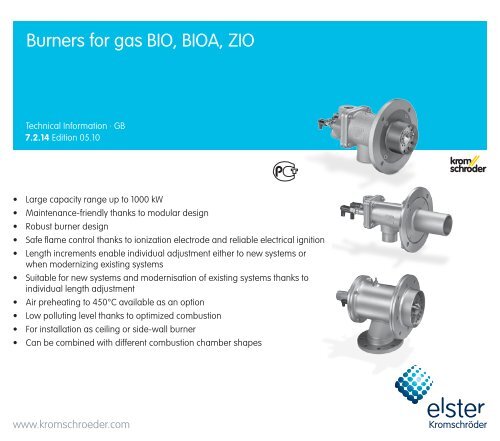
Burners for gas <strong>BIO</strong>, <strong>BIO</strong>A, <strong>ZIO</strong><br />
Technical Information · GB<br />
7.2.14 Edition 05.10<br />
• Large capacity range up to 1000 kW<br />
• Maintenance-friendly thanks to modular design<br />
• Robust burner design<br />
• Safe flame control thanks to ionization electrode and reliable electrical ignition<br />
• Length increments enable individual adjustment either to new systems or<br />
when modernizing existing systems<br />
• Suitable for new systems and modernisation of existing systems thanks to<br />
individual length adjustment<br />
• Air preheating to 450°C available as an option<br />
• Low polluting level thanks to optimized combustion<br />
• For installation as ceiling or side-wall burner<br />
• Can be combined with different combustion chamber shapes<br />
www.kromschroeder.com
2<br />
Table of contents<br />
Burners for gas <strong>BIO</strong>, <strong>BIO</strong>A, <strong>ZIO</strong> . . . . . . . . . . . . . . . . . . . . . . 1<br />
Table of contents . . . . . . . . . . . . . . . . . . . . . . . . . . . . . . . . . 2<br />
1 Application. . . . . . . . . . . . . . . . . . . . . . . . . . . . . . . . . . . . 3<br />
1.1 Examples of application. . . . . . . . . . . . . . . . . . . . . . . . . . 5<br />
1.1.1 Continuous control with pneumatic ratio control system . . .5<br />
1.1.2 Continuous control with pneumatic ratio control system<br />
and lance. . . . . . . . . . . . . . . . . . . . . . . . . . . . . . . . . . . . . . . . . . . . .5<br />
1.1.3 Cascade control for extended control range . . . . . . . . . . . .6<br />
1.1.4 Staged control with pneumatic ratio control system . . . . . .6<br />
2 Certification . . . . . . . . . . . . . . . . . . . . . . . . . . . . . . . . . . . . 7<br />
2.1 Approval for Russia . . . . . . . . . . . . . . . . . . . . . . . . . . . . . 7<br />
3 Mechanical construction. . . . . . . . . . . . . . . . . . . . . . . . . 8<br />
3.1 Burner housing (furnace flange) . . . . . . . . . . . . . . . . . . . 8<br />
3.2 Burner insert . . . . . . . . . . . . . . . . . . . . . . . . . . . . . . . . . . 8<br />
3.3 Burner tube . . . . . . . . . . . . . . . . . . . . . . . . . . . . . . . . . . . 9<br />
3.3.1 Burner tube in burner quarl. . . . . . . . . . . . . . . . . . . . . . . . . .9<br />
3.3.2 Burner tube with attachment tube . . . . . . . . . . . . . . . . . . . .9<br />
4 Function. . . . . . . . . . . . . . . . . . . . . . . . . . . . . . . . . . . . . . 10<br />
5 Selection . . . . . . . . . . . . . . . . . . . . . . . . . . . . . . . . . . . . . 11<br />
5.1 Burner type. . . . . . . . . . . . . . . . . . . . . . . . . . . . . . . . . . . .11<br />
5.2 Burner size. . . . . . . . . . . . . . . . . . . . . . . . . . . . . . . . . . . .11<br />
5.3 Burner head . . . . . . . . . . . . . . . . . . . . . . . . . . . . . . . . . 12<br />
5.4 Field of application . . . . . . . . . . . . . . . . . . . . . . . . . . . . 13<br />
5.5 Calculating the burner length . . . . . . . . . . . . . . . . . . . 14<br />
5.5.1 Burners in burner quarls . . . . . . . . . . . . . . . . . . . . . . . . . . . 14<br />
5.5.2 Burners with burner attachment tube . . . . . . . . . . . . . . . . 17<br />
5.6 Selection table . . . . . . . . . . . . . . . . . . . . . . . . . . . . . . . . 19<br />
5.6.1 Type code . . . . . . . . . . . . . . . . . . . . . . . . . . . . . . . . . . . . . . 20<br />
6 Project planning information . . . . . . . . . . . . . . . . . . . . . 21<br />
6.1 Installation . . . . . . . . . . . . . . . . . . . . . . . . . . . . . . . . . . . 21<br />
6.2 Recommended ignition transformer . . . . . . . . . . . . . . 21<br />
6.3 Non-return gas valve . . . . . . . . . . . . . . . . . . . . . . . . . . 21<br />
6.4 Flame control. . . . . . . . . . . . . . . . . . . . . . . . . . . . . . . . . 21<br />
<strong>BIO</strong>, <strong>BIO</strong>A, <strong>ZIO</strong> · Edition 05.10<br />
6.5 Hot air compensation . . . . . . . . . . . . . . . . . . . . . . . . . . 21<br />
6.6 Purging air/cooling air . . . . . . . . . . . . . . . . . . . . . . . . . 22<br />
6.7 Emissions . . . . . . . . . . . . . . . . . . . . . . . . . . . . . . . . . . . . 22<br />
6.8 Gas line connection . . . . . . . . . . . . . . . . . . . . . . . . . . . 23<br />
6.9 Air line connection . . . . . . . . . . . . . . . . . . . . . . . . . . . . 23<br />
6.10 Condition on delivery. . . . . . . . . . . . . . . . . . . . . . . . . . 23<br />
7 Technical data . . . . . . . . . . . . . . . . . . . . . . . . . . . . . . . . 24<br />
7.1 Dimensions. . . . . . . . . . . . . . . . . . . . . . . . . . . . . . . . . . . 27<br />
7.2 Ignition lance . . . . . . . . . . . . . . . . . . . . . . . . . . . . . . . . . 29<br />
8 Maintenance cycles . . . . . . . . . . . . . . . . . . . . . . . . . . . 30<br />
Feedback . . . . . . . . . . . . . . . . . . . . . . . . . . . . . . . . . . . . . . 31<br />
Contact. . . . . . . . . . . . . . . . . . . . . . . . . . . . . . . . . . . . . . . . 31<br />
t = To be continued
3<br />
<strong>BIO</strong><br />
1 Application<br />
For industrial furnaces and firing systems in the iron and steel<br />
industries in the precious, non-ferrous and light metal sector,<br />
as well as in the plastics, fibre and paper industries. Other<br />
fields of application are thermal incineration installations, as<br />
well as driers and hot-air generators.<br />
For low temperature applications (e.g. for crucible heating,<br />
radiant tube heating or hot-air generation), the burners are<br />
equipped with a heat-resistant steel attachment tube.<br />
For high temperature applications (e.g. forging furnace), the<br />
burners are used in combination with a burner quarl made<br />
from refractory concrete. Different flame shapes can be<br />
achieved by using burner quarls with a different geometry.<br />
The burner may be adapted to the system requirements using<br />
different burner lengths.<br />
<strong>BIO</strong>A<br />
<strong>ZIO</strong><br />
<strong>BIO</strong>, <strong>BIO</strong>A, <strong>ZIO</strong> · Edition 05.10
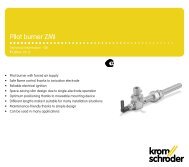
Application<br />
4<br />
Shaft melting and holding furnace Bogie hearth forging furnace Incineration installation for thermal regenerative<br />
flue air purification<br />
Strip galvanising plant Rotary table furnace Aluminium tank furnace<br />
<strong>BIO</strong>, <strong>BIO</strong>A, <strong>ZIO</strong> · Edition 05.10
Application<br />
5<br />
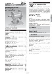
1.1 Examples of application<br />
Threepoint<br />
step<br />
AKT<br />
VAS<br />
M<br />
VAG<br />
GEH<br />
EKO<br />
EKO<br />
<strong>ZIO</strong>, <strong>BIO</strong>, <strong>BIO</strong>A<br />
1.1.1 Continuous control with pneumatic ratio control system<br />
The burner output is controlled in modulating mode by adjusting<br />
the butterfly valve BVA. The air/gas ratio control VAG<br />
ensures a constant gas/air flow ratio via the impulse line. This<br />
type of control is used in melting furnaces in the aluminium<br />
industry or in regenerative incineration installations in the<br />
environment industry, for example.<br />
IC 20 + BVA<br />
BVA<br />
AKT<br />
VAG<br />
GEH<br />
EKO<br />
<strong>BIO</strong>..L, <strong>ZIO</strong>..L<br />
1.1.2 Continuous control with pneumatic ratio control<br />
system and lance<br />
The burner’s flexibility is increased thanks to an ignition lance.<br />
This type of control is used in heat treatment furnaces in the<br />
iron and non-ferrous metal industries and in heating furnaces<br />
in the steel industry, for example.<br />
60DJZ VG 8<br />
GEH<br />
60DJLZ<br />
M<br />
GEH<br />
EKO<br />
IC 20..E + BVA<br />
BVA<br />
<strong>BIO</strong>, <strong>BIO</strong>A, <strong>ZIO</strong> · Edition 05.10
Application > Examples of application<br />
6<br />
VAS<br />
M<br />
IC 20<br />
+ LFC<br />
1.1.3 Cascade control for extended control range<br />
The burner is adjusted near-stoichiometrically to a low-fire<br />
rate of 10% using a pneumatic ratio control system. Smaller<br />
capacities can be adjusted with the IC 20 at a constant lowfire<br />
air flow rate by throttling down the gas flow. With cascade<br />
control, control ranges of 1:45 can be achieved with excess air.<br />
AKT<br />
VAS<br />
VAG<br />
GEH<br />
EKO<br />
<strong>ZIO</strong>, <strong>BIO</strong>, <strong>BIO</strong>A<br />
M<br />
IC 20 + BVA<br />
LEH<br />
EKO<br />
VAG+VBY<br />
1.1.4 Staged control with pneumatic ratio control system<br />
The burner capacity is switched cyclically between high fire<br />
and low fire by opening and closing the solenoid-operated<br />
butterfly valve for air.<br />
AKT<br />
MB 7 + BVHM<br />
GEH<br />
EKO<br />
LEH<br />
EKO<br />
<strong>BIO</strong>, <strong>BIO</strong>A, <strong>ZIO</strong><br />
The pneumatic air/gas ratio control system offers maximum<br />
safety by an air deficiency cut-out, with a constant lambda<br />
value being maintained while the air pressure varies. The<br />
low-fire rate is guaranteed by the bypass valve VBY. The high<br />
output impulse at the burner produces a uniform temperature<br />
distribution and good circulation of the furnace or kiln<br />
atmosphere, e.g. in heat treatment furnaces in the iron and<br />
non-ferrous metal industries or kilns for heavy clay and fine<br />
ceramics.<br />
<strong>BIO</strong>, <strong>BIO</strong>A, <strong>ZIO</strong> · Edition 05.10
7<br />
2 Certification<br />
2.1 Approval for Russia<br />
Certified by Gosstandart pursuant to GOST-R.<br />
Approved by Rostekhnadzor (RTN).<br />
<strong>BIO</strong>, <strong>BIO</strong>A, <strong>ZIO</strong> · Edition 05.10
8<br />
3 Mechanical construction<br />
The burners are composed of three modules: burner housing,<br />
burner insert and burner tube. This structure allows the<br />
burners to be easily adapted to the respective process or to<br />
be integrated into existing systems. Maintenance and repair<br />
times are reduced, and existing furnace installations can<br />
easily be converted.<br />
3.1 Burner housing (furnace flange)<br />
<strong>BIO</strong> <strong>BIO</strong>A <strong>ZIO</strong><br />
The burner is secured to the furnace by the burner housing.<br />
The burner housing accommodates the burner insert and the<br />
burner tube, and routes the combustion air. The combustion air<br />
pressure can be measured using an air pressure test nipple.<br />
3.2 Burner insert<br />
<strong>BIO</strong> <strong>BIO</strong>A <strong>ZIO</strong><br />
The combustion gas is supplied to the burner head via the<br />
gas connection and the gas pipe. The gas connection flange<br />
comprises of the gauge glass, ground screw and electrode<br />
plugs with plug caps.<br />
As of construction stage E, a measuring orifice and flow adjustment<br />
are integrated in the connection flange to easily measure<br />
and adjust the gas flow rate.<br />
The ignition and ionization electrodes are screwed into the<br />
connection flange and can be replaced without removing the<br />
burner insert as of burner size 65.<br />
Burners <strong>BIO</strong>, <strong>BIO</strong>A and <strong>ZIO</strong> are nozzle-mixing burners. Gas<br />
and air are mixed only once they are in the burner head. This<br />
prevents explosive gases from being generated in the pipeline.<br />
There are various burner head versions for different flame<br />
shapes and gas types.<br />
<strong>BIO</strong>, <strong>BIO</strong>A, <strong>ZIO</strong> · Edition 05.10
Mechanical construction<br />
9<br />
3.3 Burner tube<br />
Different overall lengths enable adjustment to the furnace wall<br />
thickness of the system.<br />
3.3.1 Burner tube in burner quarl<br />
The burner head is positioned inside the burner tube. The<br />
burner quarl accommodates the burner tube and simultaneously<br />
acts as the combustion chamber for the complete<br />
combustion of the flame. The burner quarls are components<br />
of the refractory lining of the furnace and are usually supplied<br />
by the furnace manufacturer.<br />
3.3.2 Burner tube with attachment tube<br />
The burner head is positioned inside the burner tube. An attachment<br />
tube made of heat-resistant steel acts as the combustion<br />
chamber for the complete combustion of the flame<br />
for low- and medium-temperature applications.<br />
<strong>BIO</strong>, <strong>BIO</strong>A, <strong>ZIO</strong> · Edition 05.10
10<br />
4 Function<br />
The burner control unit opens the gas and air control valves.<br />
Gas flows through the gas connection flange and air flows<br />
through the burner housing as far as the nozzle-mixing burner<br />
head.<br />
The combustible gas/air mixture is produced downstream of<br />
the burner head. Slots and holes in the air disc vary the degree<br />
and manner of twisting of the combustion air and determine<br />
the flame geometry. Depending on the gas type, the geometry<br />
of the gas nozzle varies.<br />
The gas/air mixture is electrically ignited directly by an ignition<br />
electrode or an ignition lance. A flame forms which is<br />
monitored using an ionization electrode or optionally using<br />
the UV sensor.<br />
The choice of the respective combustion chamber material<br />
and geometry is primarily determined by the process.<br />
Using burner quarls, almost any flame shape and outlet velocity<br />
can be achieved.<br />
For low-temperature applications, a combustion chamber<br />
made of heat-resistant steel can be used. The flame burns<br />
inside the metal burner attachment tube.<br />
<strong>BIO</strong>, <strong>BIO</strong>A<br />
<strong>ZIO</strong><br />
Burner insert<br />
Gas<br />
Burner housing<br />
Burner insert<br />
Gas<br />
Air<br />
Burner housing<br />
Air<br />
Burner head<br />
Burner tube<br />
Burner head<br />
Burner tube<br />
Burner head<br />
Ignition electrode<br />
Ionization electrode<br />
Gas nozzle<br />
<strong>BIO</strong>, <strong>BIO</strong>A, <strong>ZIO</strong> · Edition 05.10
11<br />
5 Selection<br />
5.1 Burner type<br />
Type<br />
Housing<br />
Air temperature Furnace temperature<br />
°C °C<br />
<strong>BIO</strong> GG 20 to 450 50 to 1600<br />
<strong>BIO</strong>A AlSi 20 to 200 50 to 1400<br />
<strong>ZIO</strong> ST 20 to 450 50 to 1600<br />
* For furnace temperatures of > 1450°C, special burner versions are available on request.<br />
5.2 Burner size<br />
Burner size<br />
Burner capacity<br />
[kW]<br />
<strong>BIO</strong> 50 40<br />
<strong>BIO</strong>, <strong>BIO</strong>A 65 90<br />
<strong>BIO</strong> 80 150<br />
<strong>BIO</strong> 100 230<br />
<strong>BIO</strong> 125 320<br />
<strong>BIO</strong> 140 450<br />
<strong>ZIO</strong> 165 630<br />
<strong>ZIO</strong> 200 1000<br />
<strong>BIO</strong>, <strong>BIO</strong>A, <strong>ZIO</strong> · Edition 05.10
Selection<br />
12<br />
5.3 Burner head<br />
The choice of burner head depends on the flame shape, gas type and variant.<br />
Burner head<br />
code letter<br />
Furnace temperature<br />
[°C]<br />
Air temperature2)<br />
[°C]<br />
Flame shape<br />
Control range Low fi re l λ1)<br />
Continuous Staged<br />
Normal R 1:10 1:10 > 1.05 0.8 to 1.3 50 to 350 20 to 150 4)<br />
Long H 1:10 1:10 > 1.3 0.8 to 1.5 500 to 1600 5) 20 to 450<br />
Flat K 3) – 1:10 > 1.05 0.9 to 1.2 50 to 100 4) 20 to 50 4)<br />
1) Indicates the rough range for the max. connection rating. For precise values for the individual versions, see burner diagrams.<br />
The ranges were determined for an ionization current of ≥ 5 µA. Extension of the working range using a UV sensor.<br />
2) The gas fl ow rate should be reduced in accordance with the enthalpy gain of the preheated combustion air.<br />
3) In conjunction with a burner quarl, for use as a radiant burner.<br />
4) Higher temperatures available on request.<br />
5) From a furnace temperature of > 1450°C, the control range is limited.<br />
Gas type<br />
Code letter<br />
Calorifi c value range<br />
[kWh/m 3 (n)]<br />
Density ρ<br />
[kg/m 3 ]<br />
Natural gas L and H quality B 8 to 12 0.7 to 0.9<br />
Propane, propane/butane, butane M 25 to 35 2.0 to 2.7<br />
Propane, propane/butane, butane G 1) 25 to 35 2.0 to 2.7<br />
Coke oven gas, town gas D 4 to 5 0.4 to 0.6<br />
Low calorifi c value gas L 2) 1.7 3 to 3 0.9 to 1.15<br />
1) For λ < 0.9 or when using the <strong>BIO</strong> 50.<br />
2) Not for all burner sizes. Burner capacity is limited to 50 % of the rated capacity.<br />
3) Calorifi c value range < 1.7 on request.<br />
Variant Code letter Output<br />
[kW]<br />
Ignition lance L approx. 1.5<br />
Reduced max. connection rating R –<br />
<strong>BIO</strong>, <strong>BIO</strong>A, <strong>ZIO</strong> · Edition 05.10
Selection<br />
13<br />
5.4 Field of application<br />
For optimal operation, the combustion chamber and flame shapes are combined according to the field of application.<br />
Field of application<br />
Illustration<br />
<strong>Combustion</strong><br />
chamber<br />
Control<br />
Flame<br />
shape<br />
Max.<br />
capacity<br />
Remarks<br />
Industrial furnaces, open<br />
combustion chambers<br />
A<br />
Open cone<br />
High/Low<br />
Continuous<br />
R 100 %<br />
Recommended for cold-air operating<br />
mode only, otherwise the nitric oxide values<br />
are too high<br />
Industrial furnaces, open<br />
combustion chambers<br />
B<br />
Cylindrical<br />
High/Low<br />
High/Low/Off<br />
Continuous<br />
R, H 100 % Normal to medium fl ow velocity<br />
Industrial furnaces, open<br />
combustion chambers<br />
C<br />
Tapered<br />
High/Low<br />
High/Low/Off<br />
Continuous<br />
R, H<br />
approx.<br />
80%<br />
Medium to high velocity, capacity depending<br />
on the diameter<br />
Industrial furnaces, open<br />
combustion chambers<br />
D<br />
Flat fl ame<br />
quarl<br />
High/Low<br />
High/Low/Off<br />
(Continuous)<br />
K 100 %<br />
With continuous control, limited control<br />
range (≥ 40%)<br />
Radiant tube heating<br />
E<br />
Burner with<br />
attachment<br />
tube and<br />
purging air<br />
bore holes<br />
On/Off H 100 %<br />
For cold-air only. Note the capacity of the<br />
radiant tube in accordance with the manufacturer’s<br />
specifi cations.<br />
A draught blocker must be fi tted on the<br />
fl ue gas side.<br />
Hot-air generation<br />
F<br />
Burner attachment<br />
tube<br />
with purging<br />
air bore holes,<br />
protective<br />
fl ame tube<br />
FPT<br />
High/Low<br />
High/Low/Off<br />
continuous<br />
R 100 %<br />
Protection of the fl ame from cooling is ensured<br />
by using a protective fl ame tube<br />
FPT at fl ow velocities of > 15 m/s).<br />
Only where the furnace temperature is<br />
< 600°C.<br />
<strong>BIO</strong>, <strong>BIO</strong>A, <strong>ZIO</strong> · Edition 05.10
Selection<br />
14<br />
5.5 Calculating the burner length<br />
L1<br />
L2<br />
L O<br />
BKL<br />
Legend<br />
L1 = Burner tube length<br />
L2 = Position of burner head<br />
L O = Furnace wall thickness<br />
BKL = Burner chamber length (L 10 )<br />
5.5.1 Burners in burner quarls<br />
The position of the burner head (L2) should be appropriately selected, so that the<br />
burner head extends into the burner quarl.<br />
The position of the burner head is available in the following lengths:<br />
35, 135, 235, 335 mm, etc.<br />
The burner chamber length BKL for ensuring optimum flame formation and stable<br />
burner operation can be found in the [Data table – p. 15].<br />
Determine the position of the burner head: L2 = L O - BKL<br />
The burner tube length (L1) is predefined, depending on the flame shape R, K or<br />
H: R, K burner head:<br />
L1 = L2 + 15 mm, H burner head: L1 = L2 + 65 mm<br />
Example<br />
Desired burner quarl type = B, desired flame shape = R (normal).<br />
Selected burner with 90 kW capacity = <strong>BIO</strong> 65,<br />
suitable for burner chamber length (BKL) = 115 – 265 mm.<br />
Furnace wall thickness L O = 340 mm.<br />
Calculate shortest length L2:<br />
Select maximum burner chamber length: BKL = 265 mm.<br />
L2 = LO - BKL = 340 mm - 265 mm = 75 mm.<br />
Compare L2 (here 75 mm) with standard lengths (35, 135, 235, 335 mm, etc.).<br />
Select next longest standard length L2: L2 = 135 mm.<br />
Test whether the burner chamber length BKL fits:<br />
L O - L2 = BKL ➔ 340 mm - 135 mm = 205 mm.<br />
205 mm falls into the burner chamber length range for burners <strong>BIO</strong> 65:<br />
115 – 265 mm – see [Data table – p. 15].<br />
<strong>BIO</strong>, <strong>BIO</strong>A, <strong>ZIO</strong> · Edition 05.10
Selection > Calculating the burner length > Burners in burner quarls<br />
15<br />
Data table<br />
<strong>BIO</strong>, <strong>BIO</strong>A, <strong>ZIO</strong><br />
Burner quarl type<br />
Flame shape<br />
Burner head*<br />
Burner chamber length<br />
BKL (L 10 )<br />
[mm]<br />
50 A R 215 to 265<br />
50 B, C R 115 to 265<br />
50 B, C H 115 to 265<br />
50 D KB, KG 130 to 135<br />
65 A R 215 to 265<br />
65 B, C R 115 to 265<br />
65 B, C H 115 to 265<br />
65 D KB, KM, KD 155 to 175<br />
80 A R 215 to 265<br />
80 B, C R 165 to 265<br />
80 B, C H 165 to 265<br />
80 D KB, KM 205 to 225<br />
100 A R 215 to 315<br />
100 B, C R 165 to 265<br />
100 B, C H 165 to 315<br />
100 D KB, KM 230 to 250<br />
100 D KD 170 to 190<br />
125 A R 265 to 365<br />
125 B, C R 215 to 315<br />
125 B, C H 215 to 365<br />
125 D KB 190 to 210<br />
* Flame shape: R = normal, H = long, K = fl at.<br />
Gas type: B = natural gas, M, G = propane, butane/propane, butane, D = coke oven gas,<br />
town gas.<br />
Burner quarl type<br />
BKL<br />
BKL<br />
BKL<br />
BKL<br />
∅<br />
6°<br />
A<br />
B<br />
C<br />
D<br />
<strong>BIO</strong>, <strong>BIO</strong>A, <strong>ZIO</strong> · Edition 05.10
Selection > Calculating the burner length > Burners in burner quarls<br />
16<br />
<strong>BIO</strong>, <strong>BIO</strong>A, <strong>ZIO</strong><br />
Burner quarl type<br />
Flame shape<br />
Burner head*<br />
Burner chamber length<br />
BKL (L 10 )<br />
[mm]<br />
140 A R 315 to 415<br />
140 B, C R 265 to 365<br />
140 B, C H 265 to 415<br />
140 D KB, KM 215 to 235<br />
165 A R 315 to 465<br />
165 B R 265 to 415<br />
165 B, C H 265 to 465<br />
165 D KB, KM 240 to 260<br />
200 A R 415 to 565<br />
200 B R 315 to 465<br />
200 B, C H 315 to 565<br />
200 D KB 255 to 275<br />
* Flame shape: R = normal, H = long, K = fl at.<br />
Gas type: B = natural gas, M, G = propane, butane/propane, butane, D = coke oven gas,<br />
town gas.<br />
BKL<br />
BKL<br />
∅<br />
6°<br />
A<br />
B<br />
C<br />
For further information on burner quarls – see www.docuthek.com<br />
BKL<br />
D<br />
BKL<br />
<strong>BIO</strong>, <strong>BIO</strong>A, <strong>ZIO</strong> · Edition 05.10
Selection > Calculating the burner length<br />
5.5.2 Burners with burner attachment tube<br />
Examples for fields of application<br />
E<br />
Radiant tube heating<br />
When using the burner in radiant tubes or protective flame<br />
tubes, the extended burner tube (attachment tube) acts as the<br />
combustion chamber. Burners for this field of application are<br />
supplied with purging air bore holes for optimal flame stability.<br />
The outlet diameter of the radiant tube must be reduced to<br />
the point where a pressure loss of approx. 10 mbar occurs at<br />
the burner’s rated capacity.<br />
17<br />
F<br />
Hot-air generation<br />
To generate hot air at a furnace temperature of < 600°C, burners<br />
with an attachment tube and purging air bore holes are<br />
used.<br />
At flow velocities of > 15 m/s, the protective flame tube FPT is<br />
used to protect the flame from being cooled. At flow velocities<br />
of < 15 m/s, the protective flame tube FPT is not needed.<br />
<strong>BIO</strong>, <strong>BIO</strong>A, <strong>ZIO</strong> · Edition 05.10
Selection > Calculating the burner length > Burners with burner attachment tube<br />
18<br />
L1<br />
L O<br />
L2 L 1-2<br />
Legend<br />
L1 = Burner tube length<br />
L2 = Position of burner head<br />
LO = Furnace wall thickness<br />
L 1-2 = Attachment tube length (distance<br />
from burner head to burner tube<br />
end)<br />
Calculation example<br />
Attachment tube lengths (L 1-2 ):<br />
<strong>BIO</strong>, <strong>BIO</strong>A, <strong>ZIO</strong><br />
H burner head<br />
R burner head<br />
[mm]<br />
[mm]<br />
50 115 115<br />
65 115 115<br />
80 165 165<br />
100 165 165<br />
125 215 215<br />
140 265 265<br />
165 265 165<br />
200 315 215<br />
Position of the burner head (near the interior furnace wall):<br />
L2 = L O ± 50 mm<br />
The burner tube length (L1) is calculated by adding the position of the burner<br />
head (L2) to the attachment tube length (L 1-2 ):<br />
L1 = L2 + L 1-2<br />
Example<br />
Desired flame shape = H (long) – see [Field of application – p. 13].<br />
Selected burner with 90 kW capacity = <strong>BIO</strong> 65.<br />
Attachment tube length (L 1-2 ) = 115 mm.<br />
Furnace wall thickness L O = 300 mm.<br />
Calculate shortest length L2:<br />
L2 = L O - 50 mm = 300 - 50 mm = 250 mm.<br />
Compare L2 (here 250 mm) with standard lengths (35, 135, 235, 335 mm, etc.).<br />
Select next longest standard length L2: L2 = 335 mm.<br />
Calculate the related burner tube length (L1):<br />
L1 = L2 + L1-2 = 335 mm + 115 mm = 450 mm.<br />
<strong>BIO</strong>, <strong>BIO</strong>A, <strong>ZIO</strong> · Edition 05.10
Selection<br />
19<br />
5.6 Selection table<br />
50 65 80 100 125 140 165 200 H R K B G M L D L R - 50 –… /35 – … -(1) – -(99) A – Z B<br />
<strong>BIO</strong> <br />
<strong>BIO</strong>A <br />
<strong>ZIO</strong> <br />
= standard, = available<br />
Order example<br />
<strong>ZIO</strong> 165RB-50/35-(17)D<br />
<strong>BIO</strong>, <strong>BIO</strong>A, <strong>ZIO</strong> · Edition 05.10
Selection > Selection table<br />
20<br />
5.6.1 Type code<br />
Code<br />
Description<br />
<strong>BIO</strong><br />
Burner for gas<br />
<strong>BIO</strong>A<br />
Burner for gas with aluminium housing<br />
<strong>ZIO</strong><br />
Burner for gas<br />
50 to 200 Burner size<br />
Flame shape:<br />
H<br />
long<br />
R<br />
normal<br />
K<br />
fl at<br />
B<br />
G, M<br />
L<br />
D<br />
Gas type:<br />
natural gas<br />
propane, propane/butane, butane<br />
low calorifi c value gas<br />
coke oven gas, town gas<br />
Variant:<br />
with ignition lance<br />
with reduced max. connection rating<br />
L<br />
R<br />
–50*<br />
–100**<br />
–150*<br />
–200**<br />
Burner tube length (L1) [mm]<br />
–250*<br />
–300**<br />
…<br />
/35–<br />
/135–<br />
Position of burner head (L2)<br />
/235–<br />
…<br />
-(1) to -(99) Burner head identifi er<br />
D to F<br />
Construction stage<br />
B<br />
With purging air bore holes<br />
* R, K burner head<br />
** H burner head<br />
<strong>BIO</strong>, <strong>BIO</strong>A, <strong>ZIO</strong> · Edition 05.10
21<br />
6 Project planning information<br />
6.1 Installation<br />
Installation position: any.<br />
Gas and air connection: can be rotated in 90° steps.<br />
Install and insulate the burner in order to avoid any overheating<br />
of the components during operation. Where applicable,<br />
purging air must be used to prevent ingress of aggressive<br />
gases and thermal overload of components.<br />
6.2 Recommended ignition transformer<br />
6.4 Flame control<br />
Flame control is performed using an ionization electrode or<br />
optionally using a UV sensor.<br />
6.5 Hot air compensation<br />
In order to maintain the λ constant in hot-air operating mode,<br />
the combustion air pressure is increased. The gas pressure<br />
increases in hot-air operating mode (450°C) by approx. 5 mbar<br />
for <strong>BIO</strong>..K and by approx. 10 mbar for <strong>BIO</strong>..H. The total capacity<br />
(gas capacity + hot air capacity) must not exceed the maximum<br />
possible burner capacity (see also burner operating characteristic<br />
diagrams at www.docuthek.com):<br />
Hot air capacity [%]<br />
20<br />
10<br />
≥ 7.5 kV, ≥ 12 mA, e.g. TZI 7,5-12/100 or TGI 7,5-12/100.<br />
6.3 Non-return gas valve<br />
Non-return gas valves are not required, since the burners are<br />
of the nozzle-mixing type.<br />
0<br />
0 50 100 150 200 250 300 350 400 450<br />
Hot air [°C]<br />
The air pressure is increased for a constant l.<br />
Air pressure [%]<br />
250<br />
200<br />
150<br />
100<br />
50<br />
0<br />
0 50 100 150 200 250 300 350 400 450<br />
Hot air [°C]<br />
<strong>BIO</strong>, <strong>BIO</strong>A, <strong>ZIO</strong> · Edition 05.10
Project planning information<br />
22<br />
6.6 Purging air/cooling air<br />
Cooling air at 20°C<br />
Air volume at rated capacity [%]<br />
Purging/cooling air volume for burners<br />
6<br />
5<br />
4<br />
3<br />
2<br />
1<br />
<strong>BIO</strong>/<strong>ZIO</strong>..K<br />
<strong>BIO</strong>, <strong>ZIO</strong><br />
<strong>BIO</strong>/<strong>ZIO</strong>..KB..E<br />
0<br />
0<br />
700 800 900 1000 1100 1200 1300 1400<br />
Kiln temperature °C<br />
While the burner is switched off and depending on the furnace<br />
temperature, there must be a certain air flow in order to ensure<br />
safe ignition and monitoring of the burners, and for cooling<br />
the burner components.<br />
The relative air volume in percentage values, based on the<br />
air volume for the rated capacity of the relevant size, is given<br />
in the Purging/cooling air volume for burners diagram. For<br />
hot air, the values on the right-hand axis are based on the<br />
standard air volume for the relevant rated capacity.<br />
The air fan must remain switched on until the furnace has<br />
cooled down completely.<br />
12<br />
10<br />
8<br />
6<br />
4<br />
2<br />
Cooling air at 450°C<br />
Air volume* at rated capacity [%]<br />
* The cooling air volumes measured in standard<br />
cubic metres are converted into percentage values.<br />
6.7 Emissions<br />
NOX<br />
[mg/m3]<br />
5% O2<br />
600<br />
500<br />
400<br />
300<br />
200<br />
100<br />
70<br />
50<br />
H (450 °C)<br />
R, K (20 °C)<br />
H (20 °C)<br />
K (450 °C)<br />
10 50 100<br />
Capacity [%]<br />
Flame shape:<br />
R = Normal<br />
H = Long<br />
K = Flat<br />
T Furnace<br />
= 1000°C<br />
Emissions for cold-air operating mode do not exceed the limits<br />
stipulated by the German Clean Air Directive.<br />
NO X values depend on the temperature, burner head, combustion<br />
chamber, furnace chamber, λ value and output (NO X<br />
values on request).<br />
If operated with LPG, NO X values are approx. 25% higher.<br />
<strong>BIO</strong>, <strong>BIO</strong>A, <strong>ZIO</strong> · Edition 05.10
Project planning information<br />
23<br />
6.8 Gas line connection<br />
To ensure accurate measurements of the pressure differential<br />
on the integrated gas measuring orifice, the following applies<br />
for the design of the gas connection:<br />
– Ensure undisturbed flow to the gas connection on the burner<br />
for a distance of ≥ 5 DN.<br />
– Use a bellows unit with the same nominal dimensions as<br />
the gas connection on the burner.<br />
– Use a pipe bend up to an angle of 90° with the same nominal<br />
dimensions as the gas connection on the burner.<br />
– Only use reducing nipples with an external thread at both<br />
ends in order to reduce the nominal diameter on the burner<br />
(e.g. from 1” to ¾”).<br />
To ensure optimum flow, to avoid incorrect measurements and<br />
to enable burner operation with excess gas, we recommend<br />
the following:<br />
– Do not screw the manual valve directly into the burner.<br />
6.9 Air line connection<br />
Ensure there is a bellows unit and an air adjusting cock upstream<br />
of the burner. It is recommended to install a measuring<br />
orifice FLS to determine the air flow rate.<br />
6.10 Condition on delivery<br />
Gas and air connections are fitted opposite one another at<br />
the factory.<br />
<strong>BIO</strong>, <strong>BIO</strong>A, <strong>ZIO</strong> · Edition 05.10
24<br />
7 Technical data<br />
Gas supply pressure: approx. 20 to 50 mbar,<br />
Air supply pressure: approx. 25 to 40 mbar,<br />
each depending on flame shape and gas type (gas and air<br />
pressures – see burner diagrams at www.docuthek.com).<br />
Burner length increments: 100 mm.<br />
Gas types: natural gas, LPG (gaseous) and coke oven gas;<br />
other gases on request.<br />
Heating: direct using a burner quarl or an attachment tube,<br />
indirect using a burner attachment tube inside the radiant<br />
tube.<br />
Control type:<br />
staged: On/Off, High/Low/Off,<br />
continuous: constant λ value.<br />
Most of the burner components are made of corrosion-resistant<br />
stainless steel.<br />
Housing:<br />
<strong>BIO</strong>: cast steel,<br />
<strong>BIO</strong>A: AlSi,<br />
<strong>ZIO</strong>: ST.<br />
Flame control: with ionization electrode (UV sensor as an<br />
option).<br />
Ignition: direct, electrical, lance as an option.<br />
Maximum furnace temperature:<br />
<strong>BIO</strong>/<strong>ZIO</strong> in burner quarl: up to 1600°C,<br />
with K burner head: up to 1100°C (higher temperatures on<br />
request),<br />
<strong>BIO</strong>/<strong>ZIO</strong> with burner attachment tube: up to 600°C (higher<br />
temperatures on request).<br />
Maximum air temperature:<br />
<strong>BIO</strong>, <strong>ZIO</strong>: 450°C,<br />
<strong>BIO</strong>A: 200°C.<br />
<strong>BIO</strong>, <strong>BIO</strong>A, <strong>ZIO</strong> · Edition 05.10
Technical data<br />
25<br />
Burners Rated capacity 1) Burner quarl type Flame shape code letter Flame length 2) Flame outlet velocity 3)<br />
kW cm m/s<br />
<strong>BIO</strong> 50 40 A R 25 15<br />
<strong>BIO</strong> 50 40 B R 30 55<br />
<strong>BIO</strong> 50 40 B H 35 50<br />
<strong>BIO</strong> 50 40 D K – –<br />
<strong>BIO</strong>(A) 65 90 A R 40 20<br />
<strong>BIO</strong>(A) 65 90 B R 50 70<br />
<strong>BIO</strong>(A) 65 90 B H 60 65<br />
<strong>BIO</strong>(A) 65 90 D K – –<br />
<strong>BIO</strong> 80 150 A R 45 20<br />
<strong>BIO</strong> 80 150 B R 60 75<br />
<strong>BIO</strong> 80 150 B H 70 70<br />
<strong>BIO</strong> 80 150 D K – –<br />
<strong>BIO</strong> 100 230 A R 55 20<br />
<strong>BIO</strong> 100 230 B R 70 75<br />
<strong>BIO</strong> 100 230 B H 80 70<br />
<strong>BIO</strong> 100 230 D K –<br />
<strong>BIO</strong> 125 320 A R 60 20<br />
<strong>BIO</strong> 125 320 B R 100 65<br />
<strong>BIO</strong> 125 320 B H 115 60<br />
<strong>BIO</strong> 125 320 D K – –<br />
<strong>BIO</strong> 140 450 A R 80 20<br />
<strong>BIO</strong> 140 450 B R 120 75<br />
<strong>BIO</strong> 140 450 B H 140 70<br />
<strong>BIO</strong> 140 450 D K – –<br />
<strong>ZIO</strong> 165 630 A R 90 20<br />
<strong>ZIO</strong> 165 630 B R 110 75<br />
<strong>ZIO</strong> 165 630 B H 160 70<br />
<strong>ZIO</strong> 165 630 D K – –<br />
1) Higher capacities are possible – either on request or see burner diagrams at www.docuthek.com.<br />
2) Measured in the burner quarl from the front edge of the burner quarl. The fl ame diameter is approx. one to two times that of the burner tube or burner<br />
quarl outlet.<br />
3) Refers to rated capacity, with a fl ame temperature of 1600°C for R burner head and 1500°C for H burner head. The fl ow velocity is increased when the<br />
outlet diameter of the burner quarl is reduced. The rated capacity must then be adjusted to the outlet diameter.<br />
<strong>BIO</strong>, <strong>BIO</strong>A, <strong>ZIO</strong> · Edition 05.10
Technical data<br />
26<br />
Burners Rated capacity 1) Burner quarl type Flame shape code letter Flame length 2) Flame outlet velocity 3)<br />
kW cm m/s<br />
<strong>ZIO</strong> 200 1000 A R 100 25<br />
<strong>ZIO</strong> 200 1000 B R 130 85<br />
<strong>ZIO</strong> 200 1000 B H 200 80<br />
<strong>ZIO</strong> 200 1000 D K – –<br />
1) Higher capacities are possible – either on request or see burner diagrams at www.docuthek.com.<br />
2) Measured in the burner quarl from the front edge of the burner quarl. The fl ame diameter is approx. one to two times that of the burner tube or burner<br />
quarl outlet.<br />
3) Refers to rated capacity, with a fl ame temperature of 1600°C for R burner head and 1500°C for H burner head. The fl ow velocity is increased when the<br />
outlet diameter of the burner quarl is reduced. The rated capacity must then be adjusted to the outlet diameter.<br />
<strong>BIO</strong>, <strong>BIO</strong>A, <strong>ZIO</strong> · Edition 05.10
Technical data<br />
27<br />
7.1 Dimensions<br />
d3<br />
n3<br />
h H<br />
LA<br />
L5<br />
k3<br />
D3<br />
L3<br />
S<br />
D<br />
d2<br />
F<br />
n2<br />
h H 30<br />
GA<br />
LA<br />
L5<br />
L3<br />
S<br />
D<br />
d2<br />
F<br />
n2<br />
GA<br />
L4<br />
L6<br />
L2<br />
L1<br />
k2<br />
D2<br />
L6<br />
L4<br />
L2<br />
L1<br />
k2<br />
D2<br />
L1 (burner tube length) and L2 (position of burner head) are variable (see Calculating the burner tube length)<br />
<strong>BIO</strong><br />
<strong>BIO</strong>A<br />
Burner<br />
Max.<br />
Dimensions [mm]<br />
capacity*<br />
Gas connection<br />
Air connection<br />
Weight<br />
[kW] D** GA LA H h S L3 L4 L5 L6 D2 k2 d2 n2 F D3 k3 d3 n3 [kg]<br />
<strong>BIO</strong> 50 40 50 Rp 1 / 2 Rp 1 1 / 2 50 38 12 73 149 240 127 181 151 12 4 75 – – – – 5.4<br />
<strong>BIO</strong> 65 90 65 Rp 3 / 4 Rp 1 1 / 2 62 48 12 73 156 246 127 195 165 12 4 95 – – – – 7.2<br />
<strong>BIO</strong>A 65 90 65 Rp 1 / 2 ∅ 48 80 44 16 95 170 261 149 195 165 13 4 88 – – – – 3.6<br />
<strong>BIO</strong> 80 150 82 Rp 3 / 4 Rp 2 112 55 14 90 172 272 140 240 210 14 4 110 – – – – 11.2<br />
<strong>BIO</strong> 100 230 100 Rp 1 Rp 2 100 60 16 103 185 285 153 240 200 14 4 120 – – – – 12.6<br />
<strong>BIO</strong> 125 320 127 Rp 1 1 / 2 DN 65 135 73 16 120 254 350 212 270 240 14 4 145 185 145 18 4 21.7<br />
<strong>BIO</strong> 140 450 140 Rp 1 1 / 2 DN 80 150 80 18 130 271 381 232 300 265 14 4 160 200 160 18 8 29<br />
* Cold-air connection, open fl ame, λ = 1,1<br />
** Approx. 10 cm larger in the case of a deviation from the standard length, as a weld seam is applied.<br />
<strong>BIO</strong>, <strong>BIO</strong>A, <strong>ZIO</strong> · Edition 05.10
Technical data > Dimensions<br />
28<br />
L6<br />
S<br />
d2<br />
F<br />
n2<br />
D<br />
Z<br />
I<br />
d3<br />
H<br />
GA<br />
L4<br />
LA<br />
D3<br />
k3<br />
L3<br />
L2<br />
L1<br />
k2<br />
D2<br />
<strong>ZIO</strong><br />
Burner<br />
Max.<br />
Dimensions [mm]<br />
capacity*<br />
Gas connection<br />
Air connection<br />
Weight<br />
[kW] D** GA LA H h S L3 L4 L5 L6 D2 k2 d2 n2 F D3 k3 d3 n3 [kg]<br />
<strong>ZIO</strong> 165 630 165 R 1 1 / 2 DN 100 213 – 20 150 359 – 230 285 240 14 4 ∅ 220 220 180 18 8 26<br />
<strong>ZIO</strong> 200 1000 194 R 2 DN 150 220 – 20 220 469 – 340 330 295 22 8 ∅ 255 285 240 22 8 37<br />
* Cold-air connection, open fl ame, λ = 1,1<br />
** Approx. 10 cm larger in the case of a deviation from the standard length, as a weld seam is applied.<br />
<strong>BIO</strong>, <strong>BIO</strong>A, <strong>ZIO</strong> · Edition 05.10
Technical data<br />
29<br />
7.2 Ignition lance<br />
<strong>BIO</strong><br />
Gas connection: Rp ¼.<br />
Air connection: Rp 3/8.<br />
Gas pressure: 30 to 50 mbar.<br />
Air pressure: 30 to 50 mbar.<br />
L7<br />
<strong>ZIO</strong><br />
Gas connection: Rp ¼.<br />
Air connection: Rp ½.<br />
Gas pressure: 30 to 50 mbar.<br />
Air pressure: 30 to 50 mbar.<br />
L7<br />
B<br />
E2<br />
B<br />
gas<br />
E1<br />
Air<br />
W1<br />
I<br />
Z<br />
I<br />
Z<br />
C<br />
E1<br />
air<br />
C<br />
W2<br />
E2<br />
Gas<br />
I<br />
Burner<br />
Gas Air<br />
connection connection<br />
Dimensions<br />
B C E1 E2 L7 W1 W2<br />
mm mm mm mm mm ∠ ° ∠ °<br />
<strong>BIO</strong> 80..L 57 54 7 10 177 36 45<br />
<strong>BIO</strong> 100..L 57 54 7 10 190 36 45<br />
<strong>BIO</strong> 125..L 69 65 8 8 261 30 30<br />
<strong>BIO</strong> 140..L 63 62 16 18 276 42 45<br />
Burner<br />
Gas Air<br />
connection connection<br />
Dimensions<br />
B C E1 E2 L7<br />
mm mm mm mm mm<br />
<strong>ZIO</strong> 165..L 118 77 27 71 382<br />
<strong>ZIO</strong> 200..L 137 77 27 89 482<br />
<strong>BIO</strong>, <strong>BIO</strong>A, <strong>ZIO</strong> · Edition 05.10
30<br />
8 Maintenance cycles<br />
Twice per year, but if the media are highly contaminated, this<br />
interval should be reduced.<br />
<strong>BIO</strong>, <strong>BIO</strong>A, <strong>ZIO</strong> · Edition 05.10
Feedback<br />
Finally, we are offering you the opportunity to assess this “Technical Information (TI)” and to give us your opinion, so that we<br />
can improve our documents further and suit them to your needs.<br />
Clarity<br />
Found information quickly<br />
Searched for a long time<br />
Didn’t find information<br />
What is missing?<br />
No answer<br />
Comprehension<br />
Coherent<br />
Too complicated<br />
No answer<br />
Scope<br />
Too little<br />
Sufficient<br />
Too wide<br />
No answer<br />
31<br />
Use<br />
To get to know the product<br />
To choose a product<br />
Planning<br />
To look for information<br />
Navigation<br />
I can find my way around<br />
I got “lost”<br />
No answer<br />
My scope of functions<br />
Technical department<br />
Sales<br />
No answer<br />
Remarks<br />
(Adobe Reader 7 or higher required)<br />
1 Contact<br />
Elster GmbH<br />
Postfach 2809 · 49018 Osnabrück<br />
Strotheweg 1 · 49504 Lotte (Büren)<br />
Germany<br />
T +49 541 1214-0<br />
F +49 541 1214-370<br />
info@kromschroeder.com<br />
www.kromschroeder.com<br />
www.elster.com<br />
The current addresses of our international<br />
agents are available on the Internet:<br />
www.kromschroeder.com Sales<br />
Kromschröder, a product<br />
brand of the Elster Group<br />
We reserve the right to make technical<br />
modifications in the interests of progress.<br />
Copyright © 2007 Elster Group<br />
All rights reserved.<br />
03250786<br />
<strong>BIO</strong>, <strong>BIO</strong>A, <strong>ZIO</strong> · Edition 05.10