Military Embedded Systems Summer 2006
Military Embedded Systems Summer 2006
Military Embedded Systems Summer 2006

You also want an ePaper? Increase the reach of your titles
YUMPU automatically turns print PDFs into web optimized ePapers that Google loves.
Open<strong>Systems</strong> Publishing<br />
BONUS SHOW DISTRIBUTION: GSPx, MILCOM, SDR FORUM<br />
<strong>Military</strong><br />
The COTS Technology Authority<br />
EMBEDDED SYSTEMS<br />
VOLUME 2 NUMBER 2<br />
SUMMER <strong>2006</strong><br />
I N T H I S I S S U E :<br />
Mil Tech Trends<br />
Multi-domain<br />
modeling<br />
Product Guide<br />
Multicore<br />
processor<br />
boards<br />
pg 42<br />
pg 34<br />
EXCLUSIVE INTERVIEW<br />
Former JTRS JPO Prog. Exec. Dir.
Keep your SPARC<br />
supply lines open.<br />
USP IIe VMEbus Computer<br />
650-MHz UltraSPARC ® IIi+ CPUs<br />
4GB SDRAM<br />
Optional TGA3D+ and TGA-100 graphics support<br />
Gigabit Ethernet<br />
PCI expansion to four slots<br />
Four serial ports<br />
VME Interface – VME64X via Tundra Universe II<br />
PS/2 or USB keyboard/mouse<br />
Solaris 8/9/10 Support<br />
USP IIIi VMEbus<br />
Computer<br />
Two UltraSPARC IIIi<br />
1.2 GHz CPUs<br />
4GB 266DDR SDRAM<br />
per CPU, 8GB total<br />
Optional TGA3D+<br />
and TGA-100 graphics<br />
Gigabit Ethernet port<br />
One 64-bit/66-MHz PMC slot<br />
Up to four PMC expansion slots<br />
Dual FC-AL/SCSI ports<br />
Additional VME-backplane access<br />
Up to 30G shock<br />
Solaris OS Support<br />
Stock up on<br />
Themis SPARC SBCs<br />
while supplies last.<br />
Do your mission critical applications depend on SPARC/<br />
Solaris solutions? Many suppliers are ending their support<br />
for SPARC-based single board computers. Not Themis.<br />
Themis is committed to providing its customers and<br />
industry with high performance UltraSPARC VMEbus<br />
single board computers.<br />
Themis has solutions. We are committed to providing<br />
you with the industry's widest breadth of high<br />
performance UltraSPARC-based VME single board<br />
computers. To support thousands of Solaris platform<br />
solutions for the most demanding mission critical<br />
applications.<br />
Don’t be forced into changing your computing platform<br />
today. Extend the life of your system and gain control<br />
over your program lifecycle and budget with Themis<br />
SPARC solutions.<br />
Themis is keeping the SPARC supply lines open<br />
so call Themis today.<br />
www.themis.com (510) 252-0870<br />
RSC# @www.mil-embedded.com/rsc<br />
Transformational.<br />
© <strong>2006</strong>. Themis Computer, Themis, Themis logo, TGA3D+, TGA-100, USPIIe-USB and USPIIIi are trademarks or registered trademarks of Themis Computer.<br />
All other trademarks are property of their respective owners.
Discover Condor’s Avionics<br />
<strong>Embedded</strong> Solutions<br />
1553 429 AFDX MMSI<br />
- Rugged and reliable<br />
- High performance<br />
- Advanced FPGA technology<br />
- VxWorks, Integrity, LynxOS<br />
& other RTOS supported<br />
- Test and integration tools<br />
- Intellectual property cores<br />
- ISO 9001:2000 certified<br />
- Outstanding technical support<br />
Go with the leader.<br />
It’s easy to see why<br />
we’re the leader.<br />
805.965.8000 • www.condoreng.com<br />
RSC# @www.mil-embedded.com/rsc
<strong>Military</strong><br />
V O L U M E 2<br />
N U M B E R 2<br />
S U M M E R 2 0 0 6<br />
EMBEDDED SYSTEMS<br />
w w w . m i l - e m b e d d e d . c o m<br />
DEPARTMENTS<br />
Industry Analysis<br />
8 Has crummy old technology survived?<br />
By Don Dingee<br />
Departments<br />
10 Editor’s Choice Products<br />
51 New Products<br />
By Sharon Schnakenburg<br />
Crosshairs Editorial<br />
54 What’s up with Intel and AMD?<br />
By Chris A. Ciufo<br />
6 Advertiser Index<br />
EVENTS<br />
MILCOM <strong>2006</strong><br />
Oct. 23-25, <strong>2006</strong> • Washington, DC<br />
www.milcom.org<br />
GSPx<br />
Oct. 30-Nov. 2, <strong>2006</strong> • Santa Clara, CA<br />
www.gspx.com<br />
SDR Forum<br />
<strong>2006</strong> Software-Defined Radio Technical Conference<br />
and Product Exposition<br />
Nov. 13-17, <strong>2006</strong> • Orlando, FL<br />
www.sdrforum.org<br />
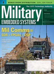
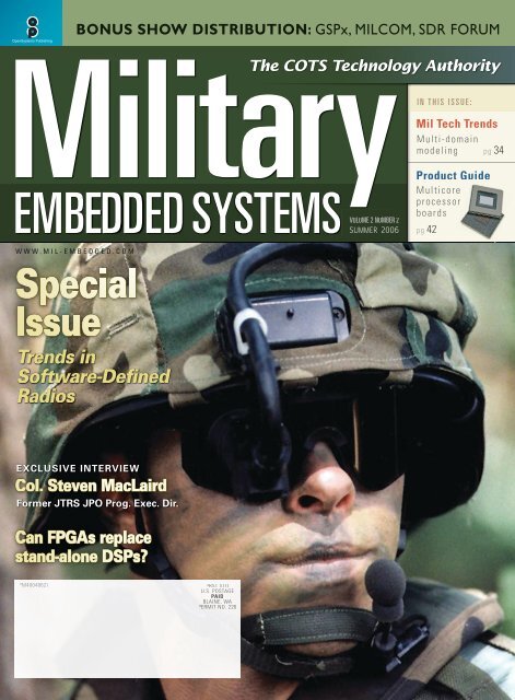
COVER<br />
The U.S. Army’s Land Warrior program calls for network-centric assets relying on a Soldier of One.<br />
Lightweight reconfigurable Joint Tactical Radio System (JTRS) equipment is essential for digital<br />
information exchange – depending on critical DSP, FPGA, and COTS software. Related articles<br />
appear on pages 12 and 22. (Image courtesy of the U.S. Army)<br />
On the cover<br />
The IBM Cell processor implements a 64-bit PowerPC core with eight additional synergistic cores,<br />
allowing up to 10 simultaneous threads and more than 128 outstanding memory requests.<br />
Published by:<br />
© <strong>Military</strong> <strong>Embedded</strong> <strong>Systems</strong><br />
All registered brands and trademarks within <strong>Military</strong> <strong>Embedded</strong> <strong>Systems</strong> magazine are the<br />
property of their respective owners.<br />
Open<strong>Systems</strong><br />
Publishing <br />
4 / SUMMER <strong>2006</strong> MILITARY EMBEDDED SYSTEMS<br />
FEATURES<br />
HARDWARE: Reconfigurable FPGAs<br />
12 Board vendor FPGA toolkits make or break your project<br />
By Mark Littlefield, Curtiss-Wright Controls <strong>Embedded</strong> Computing<br />
16 Design strategies for an FPGA-based 256-channel digital<br />
down converter<br />
By Rodger H. Hosking, Pentek, Inc.<br />
SOFTWARE: Software-Defined Radios (SDRs)<br />
22 SDR and JTRS: Lessons learned<br />
Q & A with Col. Steven MacLaird, USAF (ret.) and former<br />
Program Executive Director of the Joint Tactical Radio<br />
System JPO<br />
26 The next advancements in Software-Defined Radio<br />
By Joseph M. Jacob, Objective Interface <strong>Systems</strong>, Inc.<br />
MIL TECH TRENDS: Design modeling<br />
34 Applying Model-Based Design to a Fault Detection,<br />
Isolation, and Recovery system<br />
By Jason Ghidella, PhD, and Pieter J. Mosterman, PhD, The MathWorks, Inc.<br />
PRODUCT GUIDE: Multiprocessors<br />
42 Migrating legacy applications to multicore processors<br />
By Paul Leroux and Robert Craig, PhD, QNX Software <strong>Systems</strong><br />
49 Multiprocessor/multicore single board computers and<br />
DSP modules<br />
E-LETTER<br />
Achieving the full-circle promise of Eclipse-based development<br />
tools: A new technology ecosystem of opportunities and risks<br />
By Marc R. Erickson, Communications and Media Arts<br />
Visit us online for the complete list of articles at www.mil-embedded.com/eletter.<br />
WEB RESOURCES<br />
Subscribe to the magazine or E-letter:<br />
www.opensystems-publishing.com/subscriptions<br />
Industry news:<br />
Read: www.mil-embedded.com/news<br />
Submit: www.opensystems-publishing.com/news/submit<br />
Submit new products:<br />
www.opensystems-publishing.com/vendors/submissions/np
The Critical Path<br />
to Transformation<br />
The Intel platform approach puts you on the critical path to transformation. The objective: deliver the<br />
most advanced, cost-effective solutions to your customers. The roadmap: multi-core processors and platform<br />
technologies from Intel complemented by a broad array of standards-based solutions from its ecosystem.<br />
The deliverables: scalable, power efcient processing for new generations of embedded applications.<br />
The results: next generation features, reduced development time and investment. The time: now.<br />
www.intel.com/go/military<br />
Copyright <strong>2006</strong>, Intel Corporation. All rights reserved. Intel and the Intel logo are trademarks or registered trademarks of Intel Corporation or its subsidiaries in the United States and other countries.<br />
©<br />
RSC# @www.mil-embedded.com/rsc
Advertiser<br />
Information<br />
Page/RSC# Advertiser/Product description<br />
52 ACT/Technico – PMC Storage<br />
48 Advantech Corporation – Stackable SBCs<br />
17 Annapolis Micro <strong>Systems</strong> – FPGA <strong>Systems</strong><br />
46 BittWare – 6U VME/VXS Board<br />
3 Condor Engineering – Avionics <strong>Embedded</strong><br />
Solutions<br />
56 Curtiss Wright – High-performance Graphics<br />
Products<br />
2701 Datametrics – Rugged Workstations<br />
39 DIGITAL-LOGIC – Microspace MSM855<br />
44 <strong>Embedded</strong> Planet – EP8548A Serial RapidIO AMC<br />
31 Excalibur <strong>Systems</strong> – Avionics Communications<br />
55 GE Fanuc <strong>Embedded</strong> <strong>Systems</strong> – <strong>Embedded</strong><br />
<strong>Systems</strong><br />
21 General Micro <strong>Systems</strong> – V394, CC61X<br />
43 GSPx – GSPx Silicon Valley <strong>2006</strong><br />
7 Harris RF Communications Division – Encryption<br />
Modules<br />
19 Hunt Engineering – USB-connected<br />
Programmable FPGA <strong>Systems</strong><br />
6 Hybricon – Liquid-cooled 100 W/Slot 1 ATR<br />
33 Hypertronics – Ruggedized Connector Solutions<br />
9 ICS Sensor Processing – ICS-8550<br />
5 Intel – <strong>Military</strong> Platforms<br />
11 Jacyl Technology – Digital FPGA and Analog FPAA<br />
45 MILCOM <strong>2006</strong> – MILCOM <strong>2006</strong><br />
41 <strong>Military</strong> and Aerospace Electronics – Technical<br />
Conference and Exhibition <strong>2006</strong><br />
53 MPL AG – Rugged <strong>Embedded</strong> Computers<br />
3701 North Atlantic Industries – <strong>Military</strong> Power<br />
Supplies<br />
47 Optima EPS – Custom Cabinets/Enclosures<br />
2702 Phoenix International – Data Storage Modules<br />
51 Real-Time Innovations – Data-critical Networked<br />
Applications<br />
28 RTD <strong>Embedded</strong> Technologies – HighRel<br />
PC/PCI-104 Modules and <strong>Systems</strong><br />
2501 TEWS Technologies – <strong>Embedded</strong> I/O Solutions<br />
2502 Thales – PENTXM2<br />
2 Themis Computer – SPARC SBCs<br />
3702 Tri-M <strong>Systems</strong> – Flash Solutions<br />
35 Tri-M <strong>Systems</strong> – CT104 Enclosure<br />
23 VMETRO – Real-Time Multiprocessors<br />
RSC# 6 @www.mil-embedded.com/rsc<br />
ISSN: Print 1557-3222<br />
<strong>Military</strong> <strong>Embedded</strong> <strong>Systems</strong> (USPS 019-288) is published four<br />
times a year (Spring, <strong>Summer</strong>, Fall, Winter) by Open<strong>Systems</strong><br />
Publishing LLC, 30233 Jefferson Avenue, St. Clair Shores, MI<br />
48082.<br />
Subscriptions are free to persons interested in the design or<br />
promotion of <strong>Military</strong> <strong>Embedded</strong> <strong>Systems</strong>. For others inside the<br />
US and Canada, subscriptions are $28/year. For 1st class delivery<br />
outside the US and Canada, subscriptions are $50/year (advance<br />
payment in US funds required).<br />
Canada: Publication agreement number 40048627<br />
Return address WDS, Station A PO Box 54, Windsor, ON N9A 615<br />
POSTMASTER: Send address changes to <strong>Military</strong> <strong>Embedded</strong> <strong>Systems</strong><br />
16872 E. Ave of the Fountains, Ste 203, Fountain Hills, AZ 85268
Take a closer<br />
look at your<br />
encryption.<br />
Are you getting the<br />
protection you need?<br />
Members of the Sierra family of encryption<br />
modules are easily integrated into<br />
communications devices of all kinds. Sierra<br />
encrypts classified information, processes<br />
data at a higher speed, is extremely power<br />
efficient, and allows modules to be reprogrammed<br />
as missions change.<br />
It's benefits like these that led the U.S.<br />
Department of Defense to select Sierra II<br />
for one of the most important communications<br />
programs in recent history. Sierra II<br />
has been chosen to encrypt 100 percent of<br />
the radios under Cluster 1 of the U.S. Joint<br />
Tactical Radio System program.<br />
Learn more at www.rfcomm.harris.com.<br />
www.harris.com<br />
B r o a d c a s t<br />
•<br />
M i c r o w a v e<br />
•<br />
R F<br />
•<br />
G o v e r n m e n t<br />
sec<br />
RSC# @www.mil-embedded.com/rsc<br />
assuredcommunications
Industry Analysis<br />
Has crummy old technology survived?<br />
By Don Dingee<br />
The seminal February 1994 Mandate for Change speech called<br />
for Commercial Off-the-Shelf (COTS) computing equipment,<br />
targeting:<br />
»<br />
»<br />
»<br />
»<br />
»<br />
Reduced system costs<br />
Decreased system design time<br />
Improved system performance<br />
Reduced dependence on single-source suppliers<br />
Combined effects reducing total acquisition costs<br />
Has COTS worked, or has crummy old technology survived?<br />
There are examples for both sides.<br />
Direct hit<br />
One case where COTS has gone right is the U.S. Navy’s<br />
AN/BQQ-10 Acoustic Rapid COTS Insertion (A-RCI) program.<br />
A-RCI integrates COTS technology into submarine sonar systems<br />
in the Los Angeles SSN-688I class and has greatly increased antisubmarine<br />
warfare processing power at the Navy’s disposal.<br />
The A-RCI design teams at Lockheed Martin packed more than<br />
twice the sonar processing power onto a single sub than existed<br />
in the entire submarine fleet theretofore. Living the philosophy<br />
of maximum density, they traversed several form factors – 6U<br />
and 9U VMEbus boards and packaging from various suppliers,<br />
2U rack-mount Pentium servers, even Apple Xserve boards<br />
repackaged to fit, looking to pack more processing into each<br />
design generation. The result: reduced system costs of about<br />
20 percent over each generation of deployment. This program<br />
definitely hit the target intended for COTS.<br />
Wide left and wide right<br />
I’m aware of two recent examples of COTS selection that I<br />
believe went wrong, for different reasons:<br />
»<br />
»<br />
The SSGN program converts U.S. Navy ballistic missile<br />
submarines to cruise missile firing and special operations<br />
deployment capabilities. Its Vertical Launch Subsystem (VLS)<br />
called for a VMEbus processor board. During competitive<br />
bids in 2002, the prime contractor requested the bill of<br />
material for each board. Fifteen obsolete parts were found on<br />
the winning board at the time of selection, and the plan was<br />
for the U.S. Navy to procure a lifetime inventory for each<br />
of those obsolete parts. Buying and storing more and more<br />
crummy old technology as the list of obsolete components on<br />
a board grows over time doesn’t make much sense.<br />
The Digital Airport Surveillance Radar (DASR), jointly<br />
managed by the U.S. Air Force and Federal Aviation<br />
Administration, detects aircraft position and weather<br />
conditions near civilian and military airfields. The ASR-11<br />
– or its analog predecessor – is the large, orange, rotating<br />
cattle gate seen on the perimeter of most large airfields today.<br />
ASR-11 decided to borrow proven COTS technology from the<br />
Mode Select Beacon (or Mode-S) program, which completed<br />
a successful upgrade to a 68040 VMEbus board between 1998<br />
and 2003. One small problem: By the time ASR-11 started<br />
deployment in 2003, the 68040 VMEbus board was ready to<br />
retire and finally did in 2004. The selection of crummy old<br />
technology for a compute engine can be a major setback, even<br />
if it feels safer at the time.<br />
Old habits die hard<br />
<br />
What conditions help COTS computing gear work for a program?<br />
<br />
Three seem to be important:<br />
1. Aligned thinking. Directorate and program office teams and<br />
<br />
the contractor management teams must not only stand behind<br />
<br />
the concept of COTS but proactively break down traditional<br />
<br />
bureaucratic barriers and thinking. And vendors need to be<br />
involved in the thinking, too.<br />
<br />
2. Shorter life cycles. Keeping design cycles as short as possible<br />
<br />
provides greater freedom in selecting computing technology,<br />
and planning for faster insertions of new technology keeps<br />
the total system life cycle short.<br />
3. Fixed scope. Design teams should know more about their<br />
scope such as how many units they have to field, when<br />
decisions must be made, and when systems must be deployed.<br />
This helps contain risks, leverage knowledge from previous<br />
design cycles, and succeed while moving forward quickly.<br />
If the scope increases, the technology should be able to<br />
change.<br />
Get off that crummy old technology<br />
Creating any significant change is hard. Vendors, contractors,<br />
and the military need to work together to get COTS right more<br />
often. COTS board and system vendors are very hard-pressed<br />
to satisfy demands for the latest and greatest technology while<br />
simultaneously keeping older generations of product alive for<br />
what in today’s technology cycles can be an epoch. Get off of<br />
the old stuff.<br />
Is COTS working for your program or not, and why? We would<br />
love to hear from you, and you can reach me at ddingee@<br />
opensystems-publishing.com.<br />
<br />
/ SUMMER <strong>2006</strong><br />
<strong>Military</strong> EMBEDDED SYSTEMS
RSC# @www.mil-embedded.com/rsc
Editor’s Choice Products<br />
JTRS<br />
waveforms<br />
made easy<br />
easier<br />
The DoD’s Joint Tactical Radio<br />
System (JTRS) is a huge program that<br />
has boatloads of software at its core. Of primary importance are the SCA core<br />
framework and the portable waveforms that must work on myriad equipment<br />
while interoperating with older, hard-wired radios. Therefore, writing code for<br />
JTRS equipment can be a real nightmare. At least, that’s the problem that<br />
Zeligsoft is trying to solve with its Component Enabler (CE) 2.4. This JTRS<br />
development tool helps software designers determine the usability of their<br />
software components in the field, and verifies compliance against the SCA.<br />
CE 2.4 takes into account the target hardware deployment platform that the<br />
JTRS radio will ultimately run on. It also allows designers to write code and then<br />
iterate that code to balance the metrics of JTRS compliance, hardware choices,<br />
and waveform interoperability. Because of the iteration capability, the product<br />
speeds development, aids in the test phase, and ultimately saves costs.<br />
Also available in CE 2.4 are modeling, validation, and runtime analysis<br />
capabilities. Multiple application views are intended for teams working on<br />
different portions of the overall code set, while keeping track of the overall<br />
combined set of software modules. A validation feature links to SCA validation<br />
and the latest version of the SCA specs, flagging rule violations. Writing and<br />
validating code for a JTRS radio will never be easy, but Zeligsoft’s Component<br />
Enabler makes the task easier.<br />
Zeligsoft<br />
www.zeligsoft.com<br />
RSC# 30700<br />
Rugged 3U<br />
CompactPCI SBC<br />
Until the new 3U VITA 46 slim VME form<br />
factor becomes a reality later this year,<br />
3U CompactPCI is still the format of choice for retrofitting space-constrained<br />
defense systems. With ample I/O capability and a nice size that fits well into<br />
ATR boxes and some SEM-E envelopes, 3U CompactPCI is an ideal choice.<br />
Aitech Defense <strong>Systems</strong> agrees, to which their C900 MPC7447A/7448-based<br />
PowerPC SBC can attest. Screaming along at 1.167 GHz with AltiVec signal<br />
processing support, the board includes up to 1 GB of DDR SDRAM complete with<br />
ECC. (Aitech is big into space-based apps, so you’d expect they’d include ECC or<br />
other provisions to deal with radiation effects.)<br />
The board also includes 64 MB of user flash and a whopping 1 GB of NAND<br />
flash for program stores. There’s also a thoughtful 128 kB NVRAM for application<br />
variables and 32 MB of boot flash. A Marvell MV64460 Discovery III chipset<br />
offers a PCI-to-PCI-X bridge. There’s also a PMC mezzanine provision, as well<br />
as a bunch of I/O options. Two GbE ports, two USB 2.0 ports, and up to eight discrete<br />
I/O channels (or four RS-422 serial channels) round out the “goes-innas<br />
and goes-outtas.” As you’d expect from Aitech, air- and conduction-cooled<br />
versions are available. Betcha they’d even make you one that’s rad-hard.<br />
Aitech Defense <strong>Systems</strong><br />
www.rugged.com<br />
RSC# 23045<br />
Ultra-low power FPGAs<br />
The gazillion gate highly integrated FPGAs<br />
from companies ranging from A to X offer<br />
performance to spare but come with a<br />
heavy power penalty. Although VME<br />
boards have ample power budgets of<br />
up to 100 W these days, that power<br />
has to be dumped into the sys-<br />
tem somehow. If you can save power, why not do it? That’s the intention of<br />
QuickLogic’s QL8150 Eclipse II FPGAs. Designed for light-density logic applications<br />
such as handheld devices, they’re also ideal for fixed-function interface<br />
controllers on VME basecards, PMC mezzanines, active backplanes, and<br />
chassis front panels.<br />
With 188,946 maximum gates and 640 logic cells in a 32 x 32 logic array,<br />
this small 8 x 8 mm footprint BGA package uses only 196 fine-pitch balls.<br />
Power consumption varies, but think battery powered and you’re in the right<br />
realm. The devices are designed to operate over a -40 °C to +100 °C temperature<br />
range, so deployment in conduction-cooled VME chassis should be<br />
no problem.<br />
QuickLogic<br />
www.quicklogic.com<br />
RSC# 30701<br />
PDA’s protective skin<br />
saves soldiers’ lives<br />
Anyone with an iPod knows that a protective<br />
case called a skin protects the unit from scuffs<br />
and scratches and cushions it for the inevitable<br />
drop onto concrete. OtterBox cases protect<br />
iPods, tablet PCs, portable GPS units, and myriad<br />
other handheld electronic devices. But recently,<br />
Otter Products’ OtterBox 1900 PDA case has<br />
been used to save lives when coupled with an<br />
HP iPAQ hx4700.<br />
The company worked with the U.S. Army’s Medical Research and Materiel<br />
Command’s Medical Communication for Combat Casualty Care (MC4) and the<br />
Telemedicine and Advanced Technology Research Center (TATRC) to cocoon<br />
the iPAQ for battlefield medical needs. TATRC’s Battlefield Medical Information<br />
System Tactical – Joint (BMIST-J) allows Army tactical medical forces to<br />
quickly and securely document patient information at the point of injury. The<br />
system replaces the World War II vintage paper DD Form 1380. Without the<br />
OtterBox 1900 PDA case, the iPAQ would never survive the rigors of life on the<br />
front lines, including moisture, dust, shock, and vibration.<br />
MC4 has deployed more than 12,000 OtterBox and BMIST-J systems, with a<br />
savings of more than $1,000 per unit compared to a purpose-built rugged PDA<br />
costing upwards of $1,500 each. Otter Products also manufactures numerous<br />
other protective skins for civilian and custom handhelds.<br />
Otter Products<br />
www.otterbox.com<br />
RSC# 31423<br />
Editor’s Choice Products are drawn from OSP’s product database and press releases. Vendors may add their<br />
new products to our website at www.opensystems-publishing.com/vendors/submissions/np/ and submit press<br />
releases at www.opensystems-publishing.com/news/submit. OSP reserves the right to publish products based on<br />
editors’ discretion alone, and does not guarantee publication of any product entries.<br />
10 / SUMMER <strong>2006</strong> MILITARY EMBEDDED SYSTEMS
RSC# 11 @www.mil-embedded.com/rsc
Hardware<br />
Reconfigurable FPGAs<br />
Board vendor FPGA toolkits make<br />
or break your project<br />
By Mark Littlefield<br />
FPGAs dramatically accelerate DSP<br />
designs while bringing reconfigurability<br />
to the battlefield. But to wring out<br />
performance, ease-of-use, and overall<br />
program benefits, a design toolkit is<br />
needed. Better choose wisely.<br />
Increasingly, the military community<br />
is recognizing that there is a class<br />
of signal processing that is now best<br />
accomplished via a reconfigurable computing<br />
implementation instead of the<br />
traditional method of software running<br />
on microprocessors. Modern Field Programmable<br />
Gate Arrays (FPGAs) have<br />
reached a level of density, speed, and cost<br />
such that system designers can now often<br />
achieve a tenfold reduction in size and<br />
power when compared with the traditional<br />
microprocessor-based approach. The<br />
power of FPGAs stems from the<br />
opportunity to parallelize operations that<br />
a microprocessor must do sequentially.<br />
For many signal processing designers,<br />
the question is not whether the use of<br />
FPGAs will result in higher performance<br />
– performance/power/cost – but whether<br />
the R&D investment will pay off. The<br />
simple fact is that developing signal<br />
processing functions in FPGAs has high<br />
technical risk, which can result in cost<br />
and schedule overruns.<br />
When selecting a COTS board level<br />
product, a system integrator should<br />
be aware that the board vendor FPGA<br />
supporting toolkit will play a large role<br />
in reducing (or not) this technical risk.<br />
Herein, we will acquaint the reader with<br />
the nature of such tools and their effect on<br />
the cost of developing an FPGA compute<br />
solution.<br />
What is an FPGA toolkit?<br />
In our context, an FPGA toolkit is the<br />
collection of supporting IP (VHDL<br />
designs) and other software components<br />
that are offered for use by the vendor of<br />
a board level product. We are not talking<br />
about the synthesis and simulation tools<br />
that are the domain of the FPGA silicon<br />
vendors and other tool specialists.<br />
The components of an FPGA board<br />
toolkit fall into four categories:<br />
• IP designs to control hardware<br />
features, for example, an SDRAM<br />
controller<br />
• IP infrastructure to connect IP blocks<br />
together<br />
• Software for system services, data<br />
movement, and general system<br />
integration<br />
• Simulation and test<br />
To appreciate the key attributes of these<br />
toolkit components, consider the Curtiss-<br />
Wright CHAMP-FX, an FPGA processing<br />
board designed for military signal<br />
processing applications. The CHAMP-<br />
FX, illustrated in Figure 1, integrates the<br />
Xilinx Virtex-II Pro FPGAs (VP70/100)<br />
with local memories, PCI interfaces, and<br />
high-speed serial interfaces.<br />
The combination of DDR SDRAM for<br />
bulk storage and DDR SRAM for fast,<br />
nonsequential storage of algorithm data<br />
allows flexibility in mapping algorithms to<br />
this architecture. In a typical application,<br />
data may first flow into SDRAM with<br />
intermediate storage in SRAM for<br />
algorithm processing with results output<br />
via the PCIbus to StarFabric or an<br />
alternate interface provided by a PMC<br />
module. In such dataflow architectures,<br />
the performance and ease of use of the<br />
memory controllers can dictate the overall<br />
performance of the application.<br />
Robust IP blocks are critical<br />
Implementing a memory controller provides<br />
an example of the criticality of the<br />
design kit to the success of a project. While<br />
it is possible to obtain free designs for an<br />
SDRAM controller from FPGA vendors,<br />
be advised that these are often limitedfunction<br />
reference designs. Experience<br />
has shown that it takes many man-months<br />
of experienced FPGA designer time to<br />
implement a high-performance, reliable<br />
SDRAM controller for FPGA-based<br />
hardware. The challenges that emerged<br />
– not unexpected – emanate from classic<br />
FPGA design issues. Examples of some<br />
of these design issues follow:<br />
During the read cycle of a DDR SDRAM,<br />
the FPGA sends out a clock to the<br />
SDRAM and waits two cycles for a<br />
four-word burst to return. The challenge<br />
is in clocking the data back from the<br />
SDRAM. There is skew between the<br />
12 / SUMMER <strong>2006</strong> <strong>Military</strong> EMBEDDED SYSTEMS
Reconfigurable FPGAs<br />
Hardware<br />
PMC/XMC<br />
Site1<br />
Front Panel Rocket IO<br />
Up to 3.125 Gbps/2.5 GBps<br />
SDRAM<br />
64 MB<br />
Flash<br />
128 MB<br />
Front Panel Rocket IO<br />
Up to 3.125 Gbps/2.5 GBps<br />
PMC/XMC<br />
Site 2<br />
P2 via mux<br />
Front Panel<br />
8-bits- LVTTL<br />
EIA-232<br />
Serial<br />
PowerPC<br />
405<br />
Configurator<br />
Ethernet<br />
(future)<br />
I 2 C<br />
10/100<br />
Ethernet Phy<br />
Temperature &<br />
current sensors<br />
Front Panel RJ 45<br />
Direct PHY to P2<br />
PCI<br />
FPGA<br />
Loader<br />
PCI<br />
DDR II SRAM<br />
18 MB<br />
DDR SRAM<br />
256 MB<br />
DDR II SRAM<br />
18 MB<br />
DDR SRAM<br />
256 MB<br />
PCIe<br />
(x4)<br />
SRAM<br />
Control<br />
User<br />
Logic<br />
SDRAM<br />
Control<br />
SRAM<br />
Control<br />
User<br />
Logic<br />
SDRAM<br />
Control<br />
PCIe<br />
(x4)<br />
PCI<br />
64/66<br />
RocketIO<br />
PCI<br />
IPIC<br />
Switch<br />
PowerPC<br />
405<br />
IFB<br />
Misc IO<br />
RocketIO<br />
64-bit bus<br />
IFB<br />
Misc IO<br />
RocketIO<br />
IPIC<br />
Switch<br />
PowerPC<br />
405<br />
RocketIO<br />
PCI<br />
PCI<br />
64/66<br />
Xilinx Virtex-II Pro VP70/100<br />
Xilinx Virtex-II Pro VP70/100<br />
StarFabric<br />
Bridge<br />
StarFabric<br />
Bridge<br />
P2<br />
RocketIO (each FPGA)<br />
4-bits up to 3.125 Gbps -----> 2.5 GBps<br />
VITA-41 PO Connector<br />
P2<br />
transmitted clock and the data (due to<br />
180 ps/inch PWB trace delay), so this is<br />
not an optimal approach to use. A better<br />
approach is to use a phase-shifted clock<br />
within the SDRAM controller IP that can<br />
account for the PWB trace length and<br />
transmission characteristics. This allows<br />
the FPGA to clock in read data with the<br />
appropriate timing margins. Because the<br />
FPGA SDRAM controller is working with<br />
externally connected devices, the design<br />
must take into account the specific FPGA<br />
pins used for the interface, the placement<br />
of the controller within the FPGA, and<br />
the PWB track lengths. At the 132 MHz<br />
operating frequency of the SDRAM<br />
interface, there is the narrow 2-3 ns<br />
window during which the data is valid.<br />
Debugging the interface between FPGA<br />
and memories is further complicated by<br />
Figure 1<br />
modern BGA packages that preclude the<br />
use of oscilloscopes and logic analyzers.<br />
If it is not working, it is very difficult to<br />
diagnose the cause of the problem.<br />
FGPA designs must adhere to simultaneous<br />
switching output rules. When<br />
too many outputs from a particular<br />
bank switch at the same time, noise is<br />
introduced into the system, which can<br />
cause data errors to occur. This is another<br />
subtlety of FPGA IP design that is<br />
difficult to debug because the errors are<br />
somewhat random and analog in nature.<br />
There is significant effort required to get<br />
a memory controller to function correctly.<br />
Getting controllers to work at high speeds<br />
(200 MHz SDRAM, 132 MHz SDRAM)<br />
also requires particular attention be paid<br />
to the placement of the IP blocks within<br />
the FPGA. A robust design optimized for<br />
a particular hardware implementation<br />
will include carefully selected and tested<br />
constraint information that ensures that<br />
the complete design, when integrated with<br />
the user’s logic, will continue to operate<br />
within timing requirements. Figure 2,<br />
a sample floorplan, shows an example<br />
of the placement of IP blocks that have<br />
been constrained to particular placement<br />
within the FPGA. This is taken from<br />
the Xilinx ISE floor planning tool. The<br />
colors represent different IP blocks. The<br />
constraint files tell the placement tool<br />
to place all the logic for a given block<br />
within a certain area. This helps ensure<br />
repeatable timing within the block and<br />
makes it less sensitive to the logic the<br />
user is adding.<br />
<strong>Military</strong> EMBEDDED SYSTEMS SUMMER <strong>2006</strong> / 13
Hardware<br />
Reconfigurable FPGAs<br />
Local Link is a packet-oriented interface<br />
for streaming data applications. In a DSP<br />
application, it is common for sensor data<br />
– digitized RF, electro-optical, and sonar<br />
– to arrive in nonaddressed packet form.<br />
The RocketIO controllers (3.125 Gbps)<br />
are supported with Local Link interfaces<br />
and DMA controllers to direct streaming<br />
data into memory-addressed locations.<br />
To simplify the interconnection of user IP<br />
with the toolkit IP modules, the company<br />
has developed an IPIC switch, which<br />
allows modules with IPIC or Local Link<br />
interfaces to connect together seamlessly<br />
(see Figure 3). Multiple IPIC switches<br />
can be instantiated in the design, allowing<br />
users flexibility in choosing the best<br />
solution.<br />
Last but not least is the added challenge<br />
presented by the wide temperature ranges<br />
encountered in military applications.<br />
The typical environmental requirement<br />
of -40 ºC to +85 ºC translates to an even<br />
wider range of -40 ºC to +110 ºC for the<br />
silicon. The design tools provide estimates<br />
of the timing effects over temperature,<br />
but only costly environment testing can<br />
verify the real effects, which will rarely<br />
be exactly as predicted. The design kit<br />
IP, if prequalified to this temperature,<br />
removes this as a risk item.<br />
Figure 2<br />
14 / SUMMER <strong>2006</strong> <strong>Military</strong> EMBEDDED SYSTEMS<br />
Interconnecting IP blocks<br />
It is desirable for IP controllers and<br />
functional blocks provided as part of a<br />
toolkit to adhere to a consistent interface<br />
standard. Common interfaces ease IP<br />
block integration. We have adopted two<br />
interface conventions defined by Xilinx,<br />
IP Interconnect (IPIC) and Local Link.<br />
Memory mapped interfaces adhere to<br />
the IPIC standard, allowing an IP block<br />
to read or write to a memory address<br />
or register. SDRAM, SRAM, and the<br />
PCIbus are provided with IPIC interfaces.<br />
Simulation: Don’t take it<br />
for granted<br />
FPGA signal processor designs are<br />
complex and, unlike software, are not<br />
easily instrumented for testing purposes.<br />
(There is no printf()!) The rule of<br />
thumb for a complex project is that<br />
simulation is 50 percent of the effort. It<br />
is fairly obvious that the FPGA vendor<br />
simulation tools can simulate the logic<br />
within the FPGA, but unless models are<br />
provided for external devices connected<br />
to the FPGA, the simulation cannot<br />
include interaction with these devices. A<br />
good FPGA toolkit will offer a test-bench<br />
environment that includes models of all<br />
the external interfaces, the capability to<br />
initialize memory interfaces and pass data<br />
from PCI and RocketIO into the FPGA<br />
and check memory, and the capability<br />
to test PCI or RocketIO data against<br />
expected data previously stored in files.<br />
The toolkit should provide a scripting<br />
language to facilitate the simulation of<br />
the design with test data and the capture<br />
of output data into files for comparison<br />
against expected results.<br />
Unless a good simulation environment is<br />
part of the toolkit, the customer will be<br />
faced with a great deal of unplanned effort<br />
to establish a test environment. Figure<br />
4 depicts the simulation models that are<br />
supplied with the CHAMP-FX design kit,<br />
and the logical points where data can be<br />
input or output from the simulation.
Reconfigurable FPGAs<br />
Hardware<br />
PCI Master IP<br />
IPI Ctrl/Data<br />
IPIC Switch<br />
IPT Ctrl/Data<br />
SRAM User IP IP<br />
User IP<br />
IPI Ctrl/Data<br />
IPT Ctrl/Data<br />
SRAM User IP IP<br />
User IP<br />
IPI Ctrl/Data<br />
Crossbar<br />
IPT Ctrl/Data<br />
SRAM User IP IP<br />
User IP<br />
IPI Ctrl/Data<br />
IPT Ctrl/Data<br />
RocketIO User IP IP<br />
User IP<br />
IPI Ctrl/Data<br />
Figure 3<br />
The final stage of testing requires loading<br />
and running the logic on the target<br />
hardware and integrating the design with<br />
the rest of the system. Despite efforts<br />
to accurately simulate a design, there<br />
remains a possibility that it will not<br />
work as intended. The Xilinx Chipscope<br />
logic analyzer is a great tool to probe<br />
the internals of a design in real time<br />
and to deduce where a problem resides.<br />
The use of Chipscope, however, requires<br />
some support within the FPGA toolkit to<br />
simplify including it in the design, so a<br />
Intra-FPGA<br />
bus Model<br />
RocketIO<br />
Model<br />
FPGA<br />
prospective customer would be advised<br />
to check into its support. Once the FPGA<br />
bitstream design is stable, the integration<br />
effort is eased by the availability of a rich<br />
set of software APIs for device control,<br />
data movement, and interprocessor<br />
synchronization.<br />
The quality and coverage of the FPGA<br />
toolkit that accompanies a COTS FPGA<br />
board is critical to the schedule and cost<br />
of an FPGA-based project. Since FPGA<br />
toolkits are like software in some respects,<br />
File driven simulation data<br />
Points of comparison of simulation<br />
versus expected result<br />
SRAM<br />
Models<br />
the quality, performance, and functionality<br />
can take some extra effort to ascertain.<br />
This extra time is well spent, since any<br />
one of the issues discussed herein could<br />
result in many man-months to resolve.<br />
Mark Littlefield is the<br />
product marketing<br />
manager for Curtiss-<br />
Wright Controls<br />
<strong>Embedded</strong> Computing’s<br />
FPGA computing<br />
product line. He has more than 15 years<br />
of experience in the embedded<br />
computing industry, first as an engineer<br />
developing robot vision systems for<br />
NASA, and later as a field applications<br />
engineer, technical program manager,<br />
and product manager. Mark has a BS<br />
and an MS degree in Control <strong>Systems</strong><br />
Engineering from the University of West<br />
Florida.<br />
To learn more, contact Mark at:<br />
PCI Model<br />
Clock<br />
Generation<br />
Model<br />
Figure 4<br />
SDRAM<br />
Models<br />
Curtiss-Wright Controls <strong>Embedded</strong><br />
Computing<br />
741-G Miller Dr. SE<br />
Leesburg, VA 20175<br />
Tel: 703-779-7800<br />
Fax: 703-779-7805<br />
E-mail:<br />
Mark.Littlefield@curtisswright.com<br />
Website: www.cwcembedded.com<br />
<strong>Military</strong> EMBEDDED SYSTEMS SUMMER <strong>2006</strong> / 15
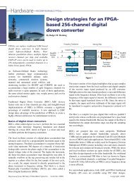
Hardware<br />
Reconfigurable FPGAs<br />
Design strategies for an FPGAbased<br />
256-channel digital<br />
down converter<br />
By Rodger H. Hosking<br />
FPGAs can replace traditional ASIC-based<br />
digital down converters in high channel<br />
count Software-Defined Radios. Their<br />
inherent parallelism allows multiple digital<br />
receiver channels per chip, and available<br />
COTS IP cores can be used to realize up to<br />
256 independently controlled channels in a<br />
Xilinx Virtex family FPGA.<br />
WideBIN<br />
Complex<br />
Input<br />
As Software-Defined Radio technology<br />
further penetrates large communication<br />
systems for battlefield military radio<br />
networks, commercial wireless systems,<br />
manned and unmanned aerial vehicles, and<br />
monitoring facilities for SIGINT and COMINT, the need to<br />
accommodate a large number of agile frequency channels for<br />
radio receivers is quite apparent. In each of these applications,<br />
the same critical metrics apply: size, weight, power, and cost for<br />
each receiver channel.<br />
Traditional Digital Down Converter (DDC) ASIC devices<br />
feature only one to four channels per chip, and straightforward<br />
implementations of DDCs in FPGAs consume a significant<br />
percentage of available resources. A new approach to DDC<br />
design takes advantage of the parallelism of FPGAs to create a<br />
highly efficient architecture for multichannel receivers.<br />
Basics of digital down converters<br />
DDCs, often called digital receivers, perform the two essential<br />
software radio functions: frequency translation and channel<br />
filtering. In a basic DDC shown in Figure 1, a mixer and local<br />
oscillator perform the frequency translation.<br />
The local oscillator consists of a digital phase accumulator that<br />
advances each clock by a programmable increment equal to the<br />
tuning frequency. The phase accumulator is a register whose fullscale<br />
value represents 360 degrees of a sinusoid. A sine/cosine<br />
lookup table converts the phase angle of the accumulator to the<br />
digital voltage value of the sinusoid. The higher the increment,<br />
the faster the phase accumulator steps through the sine table. It<br />
naturally overflows at the top, preserving any residue left in the<br />
register as a phase offset for the first sample of the next cycle.<br />
As a result, the output sinusoid is directly proportional to the<br />
phase increment or frequency setting. This block is a classic<br />
Numerically Controlled Oscillator (NCO), also often called a<br />
Direct Digital Synthesizer (DDS).<br />
16 / SUMMER <strong>2006</strong> <strong>Military</strong> EMBEDDED SYSTEMS<br />
I<br />
Q<br />
16<br />
16<br />
Digital<br />
Local<br />
Oscillator<br />
Frequency Translation<br />
Complex Mixer<br />
Sin/Cos LUT<br />
Phase Accum<br />
Tuning Frequency<br />
I<br />
Q<br />
FIR Lowpass<br />
Complex Filter<br />
Coefficient LUT<br />
Filter Coefficients<br />
Figure 1<br />
Channel Filter<br />
Decimator<br />
& Formatter<br />
The mixer consists of two digital multipliers that accept complex<br />
sine/cosine outputs from the local oscillator and digital samples<br />
of the receiver input signal produced by an A/D converter.<br />
Multiplication in the time domain produces a sum and difference<br />
signal in the frequency domain. If the local oscillator is set to the<br />
frequency of the input signal of interest, the difference term will<br />
be that input signal translated down to 0 Hz. Since the mixer is<br />
complex, the upper and lower sidebands of the input signal will<br />
be translated to negative and positive frequencies centered at 0<br />
Hz.<br />
The filter is a complex low-pass digital filter with two parallel I<br />
and Q arms whose coefficients are programmed for a pass band<br />
equal to the channel bandwidth. Because the output of the filter is<br />
bandlimited, the output decimation stage can drop the sampling<br />
rate accordingly.<br />
DDCs are grouped into two main categories. Wideband<br />
DDCs have output channel bandwidths typically above<br />
1 MHz and are appropriate for wideband Code Division Multiple<br />
Access (CMDA) and radar applications. Narrowband DDCs with<br />
bandwidths below 1 MHz are widely used for Frequency Division<br />
Multiplexed (FDM) systems including voice and music channels<br />
for telecom and commercial broadcast systems. While the mixer<br />
and local oscillator sections are quite similar for all DDCs, the<br />
best filter design depends on the filter bandwidth. For wideband<br />
channels, a conventional FIR filter is best (as shown in Figure<br />
1). For narrowband channels, a multistage Cascaded Integrator-<br />
Comb (CIC) filter followed by an FIR to correct frequency droop<br />
is more efficient.<br />
For narrowband applications, both ASIC and FPGA Intellectual<br />
Property (IP) cores are available using CIC filter designs.<br />
I<br />
Q<br />
Decimation<br />
Factor &<br />
Output Mode<br />
I<br />
Q<br />
Real<br />
BaseBIN<br />
Digital<br />
Outputs
RSC# 17 @www.mil-embedded.com/rsc
Hardware<br />
Reconfigurable FPGAs<br />
Commercial ASICs feature as many as four channels per chip,<br />
like the popular Texas Instruments/Graychip GC4016.<br />
IP core DDCs, like the LogiCore DDC from Xilinx for its<br />
Virtex-II Pro, can be scaled for various levels of Spurious-<br />
Free Dynamic Range (SFDR) performance to use more or less<br />
of the available resources. For example, a complex DDC with<br />
84 dB SFDR consumes approximately 1,700 slices. In a mid-sized<br />
FPGA device with 24,000 available slices, only about 14 DDC<br />
channels can be accommodated. For applications requiring<br />
several dozen or even hundreds of channels, this approach can<br />
become impractical.<br />
Channelizers<br />
Because of the extremely fine resolution of its NCO tuning<br />
frequency, a true DDC can translate any input frequency<br />
component down to 0 Hz, often with 32-bit accuracy. This ability<br />
makes DDCs ideal for applications that require precise changes<br />
in tuning such as in continuous Doppler correction for satellite<br />
tracking systems.<br />
However, in other applications, a channelizer approach may<br />
be sufficient. This is a bank of equally spaced, fixed frequency<br />
band pass filters whose outputs are translated to baseband (0 Hz).<br />
One crude example of a channelizer familiar to everyone is a<br />
simple FFT. It converts a block of N time samples equally spaced<br />
in time into block of N frequency samples equally spaced in<br />
frequency. For a continuous stream of input time sample blocks,<br />
samples at a given point in successive output blocks represent a<br />
translated, band pass frequency signal or bin.<br />
By selecting the output of a particular bin, a channelizer can serve<br />
as a primitive DDC, but with extremely coarse tuning resolution<br />
determined by the number of points in the FFT, as shown in<br />
Figure 2.<br />
Another serious limitation of the FFT as a DDC is the frequency<br />
response (pass band flatness) of the bin, and rejection of energy<br />
from adjacent bins (stop band rejection). Other channelizer<br />
designs use various digital filtering techniques to split the bands<br />
with better flatness and adjacent channel rejection, but they<br />
usually require significantly more hardware than an FFT for a<br />
BIN 1<br />
BIN 2<br />
BIN 3<br />
comparable number of bins. Regardless of its design, the tuning<br />
resolution of any channelizer is simply equal to the number of<br />
bins or channel filters. As a result, channelizers may be useful<br />
for spectrum analyzers, scanners, and energy survey equipment<br />
but they are rarely used as substitutes for DDCs in software radio<br />
communication systems.<br />
Rethinking the multichannel DDC<br />
The software radio market generates a growing number of<br />
requests for DDC solutions with densities higher than the 16 or<br />
32 channels provided per board using ASICs or standard FPGA<br />
designs. Therefore, we embarked upon a mission to develop a<br />
signal processing architecture for a narrowband DDC with 64<br />
channels or more, with full tuning resolution, but with much<br />
more efficient use of FPGA resources than deploying a farm of<br />
conventional DDC cores.<br />
Each conventional DDC requires its own local oscillator (phase<br />
accumulator and sine table), mixer (two multipliers), and FIR<br />
filter (multipliers and accumulators). All of this hardware must<br />
operate at the full input sample clock rate, and clock rates for<br />
A/Ds commonly used in software radios range between 100<br />
and 200 MHz. Since this is the same clock range rating for<br />
commercial DDC IP cores, all of the hardware resources used for<br />
each channel must be dedicated to that channel.<br />
However, imagine that the input data sample rate is reduced by<br />
a factor N. By operating the DDC hardware resources required<br />
for one channel at the full clock rate, those same resources can<br />
then be multiplexed (time shared) across N channels. Of course,<br />
provisions must be made for buffering the data for all channels<br />
while multiplexing. This is usually done in RAM or in delay<br />
memory, a common feature in FPGAs.<br />
One way to achieve this input rate reduction is to split the<br />
input signal into a bank of N adjacent frequency bands using a<br />
channelizer. Then, the output sample rate for each band can be<br />
reduced by a factor of N. The output from the band containing the<br />
signal of interest can be selected as the input to any given DDC to<br />
fine tune within that band.<br />
The tradeoff question becomes: Are the resources freed up by<br />
multiplexing the DDCs more than the<br />
resources required for the channelizer? The<br />
answer lies in how efficient the channelizer<br />
can be.<br />
INPUT<br />
Sample Rate<br />
= Fs<br />
FFT<br />
1024<br />
POINTS<br />
Sample Rate<br />
= Fs/1024<br />
Amplitude<br />
Realizing the design<br />
Figure 3 shows an FPGA-based 256-channel<br />
DDC IP core that combines a channelizer<br />
stage with a multiplexed DDC stage.<br />
BIN 1022<br />
BIN 1023<br />
BIN 1024<br />
Figure 2<br />
BIN<br />
n<br />
BIN<br />
n+1<br />
BIN<br />
n+2<br />
BIN<br />
n+3<br />
Freq<br />
The crucial part of this design is the<br />
channelizer stage. It accepts a single<br />
wideband input stream and delivers a<br />
channel bank of 1,024 output bands equally<br />
18 / SUMMER <strong>2006</strong> <strong>Military</strong> EMBEDDED SYSTEMS
Reconfigurable FPGAs<br />
Hardware<br />
spaced in frequency, but with significant<br />
overlap between adjacent bands.<br />
The output sample rate of each band<br />
equals the input sample rate (Fs) divided<br />
by 256, rather than 1,024, as would be<br />
expected with a simple FFT. In fact,<br />
inside the channelizer are four highspeed<br />
1,024-point FFTs running in<br />
parallel using a proprietary windowing<br />
and overlap processing technique.<br />
The outputs of the four separate FFTs<br />
deliver samples at a rate of Fs/1024.<br />
These outputs are combined to form a<br />
single output at a sample rate of Fs/256,<br />
supporting the wider bandwidth that will<br />
sufficiently overlap adjacent bands.<br />
The next stage is a crossbar switch matrix that accepts 1,024<br />
inputs from the channelizer and delivers 256 outputs, one to<br />
each DDC channel. The switch is nonblocking so that any of the<br />
256 outputs can be independently sourced from any of the 1,024<br />
channelizer bands with no restrictions.<br />
Each of the 256 channels is tuned by a separate 32-bit frequency<br />
word, with the most significant bits sent to the switch matrix<br />
for coarse tuning. This selects the correct channel band for each<br />
channel. The least significant bits of the frequency word are used<br />
by the DDC stage for fine tuning within the selected band.<br />
Because the channelizer outputs exhibit frequency droop at the<br />
band edges, a fixed compensation FIR filter flattens the pass band<br />
to within 1 dB across a span equal to twice the band-to-band<br />
spacing.<br />
INPUT<br />
FS<br />
OVERLAPPING BINS SELECTED BIN FLATTENED BIN DDC TUNING WITHIN BIN<br />
DDC OUTPUT<br />
CHANNELIZATION<br />
STAGE<br />
1024<br />
BINS<br />
BIN 1<br />
BIN 2<br />
BIN 3<br />
FS/256<br />
BIN 1022<br />
BIN 1023<br />
BIN 1024<br />
CROSS<br />
BAR<br />
SWITCH<br />
MATRIX<br />
1024 x 256<br />
TUNING<br />
CONTROL<br />
CH 1<br />
CH 2<br />
FS/256<br />
CH 255<br />
CH 256<br />
COARSE TUNING<br />
COMP FILTER<br />
FS/256 FS/256 FS/256<br />
FINE TUNING<br />
DDC 1<br />
GAIN<br />
COMP FILTER DDC 2 GAIN<br />
COMP FILTER DDC 255 GAIN<br />
COMP FILTER DDC 256 GAIN<br />
Figure 3<br />
FS/256<br />
FS/1024 to<br />
FS/9984<br />
OUTPUT<br />
range, since the edge of that wider bandwidth would cross the<br />
edge of the flat, spurious-free region of the channelizer output.<br />
Samples of the translated signal from the mixer arrive at the<br />
decimating FIR at the channelizer output sample rate of Fs/256.<br />
Since the maximum available DDC output bandwidth is Fs/1024,<br />
the lowest decimation factor allowed in the FIR is 4.<br />
MUX<br />
OUTPUT<br />
A bank of 256 independently tuned DDC sections, each with<br />
its own local oscillator, mixer, and FIR filter, processes the 256<br />
compensated switch matrix outputs. Because the channelizer has<br />
dramatically reduced the input sampling rate to each DDC section<br />
by a factor of 256, the DDCs are implemented using highly<br />
multiplexed hardware resources and block RAM to preserve the<br />
data for each channel. A gain stage, output multiplexer, and data<br />
formatter complete the design.<br />
Performance and tradeoffs<br />
The maximum output bandwidth of this design equals the<br />
channelizer band-to-band spacing of Fs/1024. For an input<br />
sample rate of 100 MHz, this spacing is about 100 kHz. And<br />
because of the broadened response, each channelizer output<br />
has a clean pass band equal to twice the band spacing, or about<br />
200 MHz.<br />
This allows the DDC to perform fine tuning by sliding its local<br />
oscillator frequency ± 100 kHz across the selected 200 kHz<br />
channelizer band to precisely center the DDC output. Choosing<br />
a wider DDC output bandwidth would restrict the DDC tuning<br />
RSC# 19 @www.mil-embedded.com/rsc
Hardware<br />
RECONFIGURABLE FPGAs<br />
dB<br />
For narrower output bandwidths, the maximum decimation<br />
factor is determined by the complexity (number of taps) of the<br />
FIR filter, which must perform at least as well as the channelizer<br />
filter in order to maintain that dynamic range of 75 dB. Choosing<br />
a reasonable number of multiplier/accumulator stages yields an<br />
FIR filter suitable for decimation factors from 4 to 39 in steps of 1.<br />
The number of filter taps is equal to 26 times the decimation<br />
factor of the filter.<br />
Since the channelizer decimation (256) and FIR filter decimation<br />
(4 to 39) multiply, the overall range of decimation range for<br />
the entire core is 1,024 to 9,984 in steps of 256. Each of these<br />
36 available decimation factors requires its own set of filter<br />
coefficients, which are stored in a table within the FPGA. For<br />
an input clock of Fs = 100 MHz, the range of output bandwidths<br />
using the default 80 percent filter characteristic is approximately<br />
8 kHz to 80 kHz. For any decimation setting, the overall DDC<br />
channel characteristics, including the channelizer response, are<br />
shown in Figure 4.<br />
Because of the multiplexed DDC hardware, all 256 channels must<br />
have the same decimation factor setting. For high-channel count<br />
systems, this limitation is usually not an issue since it is quite<br />
common for all such channels to have the same bandwidth.<br />
Overall performance of the complete 256-channel FPGA-based<br />
DDC IP core includes a spurious-free dynamic range of 75 dB,<br />
a pass band ripple of 0.4 dB, a pass band edge droop of 1.0 dB,<br />
and frequency tuning resolution of Fs/2 32 . The maximum clock<br />
frequency depends on implementation details, but can be as high as<br />
185 MHz in a Virtex-4 FPGA with speed grade 12.<br />
The core consumes approximately 18,000 logic slices of a Virtex-4<br />
device, compared to 1,700 slices for a single channel DDC<br />
LogiCore reference design. Although there are some limitations<br />
in decimation factors and dynamic range, this new core represents<br />
an improvement in the channel-per-slice ratio by a factor of more<br />
than 20.<br />
-10<br />
-20<br />
-30<br />
-40<br />
-50<br />
-60<br />
-70<br />
-80<br />
-90<br />
0<br />
>75 dB<br />
SFDR<br />
0.4 dB<br />
PassBIN<br />
Ripple<br />
1.0 dB<br />
Edge<br />
Droop<br />
Nyquist BIN<br />
Fs / Decimation<br />
80% Usable BINwidth<br />
Figure 4<br />
20 / SUMMER <strong>2006</strong> MILITARY EMBEDDED SYSTEMS<br />
This 256-channel DDC<br />
core is available as a<br />
member of the GateFlow<br />
IP Core Library suitable<br />
for use with any Virtex-II,<br />
Virtex-II Pro, or Virtex-4<br />
product.<br />
For customers preferring to Figure 5<br />
avoid FPGA development,<br />
it can be ordered as a factory<br />
installed option to the Pentek Model 7140 Dual Transceiver PMC<br />
module (shown in Figure 5) where it occupies approximately<br />
76 percent of the Virtex-II Pro XC2VP50.<br />
Creativity beats crunch<br />
In order to keep pace with a steady flow of new FPGA device<br />
offerings, designers must continually evaluate, and often reinvent,<br />
real-time embedded computing strategies for critical military and<br />
commercial applications. Armed with a detailed understanding<br />
of new device resources, creative engineers can often approach<br />
a tough problem from a radically new angle to gain a major<br />
advantage. While many new FPGA design tools offer impressive<br />
features and improved efficiencies, these truly significant leaps<br />
in FPGA performance usually come from inspiration, not from<br />
automation.<br />
Rodger H. Hosking is Vice President and<br />
Cofounder of Pentek, Inc., where he is<br />
responsible for new product definition,<br />
technology development, and strategic<br />
alliances. With more than 30 years of<br />
experience in the electronics industry, he has<br />
authored hundreds of articles about digital signal processing.<br />
More than 10 years ago, Rodger introduced digital receiver<br />
technology to the government electronics industry through<br />
numerous presentations and his widely read publication The<br />
Digital Receiver Handbook. Prior to his current position, he<br />
served as Engineering Manager at<br />
Wavetek/Rockland and holds patents in<br />
frequency synthesis and spectrum analysis<br />
techniques. He received a BS degree in<br />
Physics from Allegheny College in<br />
Pennsylvania and BSEE and MSEE<br />
degrees from Columbia University in New<br />
York.<br />
For more information, contact<br />
Rodger at:<br />
Pentek, Inc.<br />
One Park Way<br />
Upper Saddle River, NJ 07458<br />
Tel: 201-818-5900, Ext. 228<br />
E-mail: rodger@pentek.com<br />
Website: www.pentek.com
RSC# 21 @www.mil-embedded.com/rsc
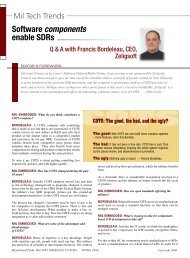
Software<br />
Software-Defined Radios (SDRs)<br />
SDR and JTRS: Lessons learned<br />
An interview with Col. Steven MacLaird, USAF<br />
(ret.) and former Program Executive Director of<br />
the Joint Tactical Radio System JPO<br />
EDITOR’S FOREWORD<br />
Col. Steven MacLaird managed the Joint Tactical Radio System (JTRS) Joint Program Office (JPO) from 2000 until his<br />
retirement from the U.S. Air Force in 2005. JTRS is one of the DoD’s largest programs, which I include with the “big<br />
three” of the Joint Strike Fighter F-35 and Future Combat <strong>Systems</strong>. Last year, I estimated that over the program’s life,<br />
somewhere between $12-$15 billion would be spent on JTRS radios and infrastructure (download available at<br />
http://meecc.com/presentations/CIUFO.pdf).<br />
Steven successfully navigated a challenging program, rife with technical, financial, and programmatic obstacles. Today,<br />
the JTRS clusters have been renamed and shuffled around, and the program is realigning its timetable for initial deployment<br />
over the next 12 months. He has been selected to sit on the board of directors of PrismTech, a COTS supplier of<br />
the Software Communications Architecture (SCA) that’s essential to JTRS. I had the privilege of speaking with him last<br />
April. Edited excerpts from that conversation follow. – Chris Ciufo<br />
MIL EMBEDDED: Please provide a brief overview of the<br />
current JTRS radios and explain how they relate to the<br />
previous clusters.<br />
MACLAIRD: In March of last year a hand off was initiated between<br />
the old [Joint Program Office] organization and the new,<br />
and I went in and briefed Dennis Bauman on the program. And<br />
we provided to him a way ahead on the organizational structure.<br />
He’s adopted a large set of that, which you have undoubtedly<br />
seen in the press.<br />
The ground domain consists of Ground Mobile Vehicles (GMV)<br />
radios and the Handheld/Manpack/Small form fit (HMS) radios,<br />
i.e., Cluster 1 and Cluster 2. Special radios used to be Cluster 2,<br />
also known as JTRS Enhanced MBTR (JEM). The airborne<br />
maritime fixed site domain is made up by the AMF program,<br />
which previously, probably about November 2004 was to be the<br />
airborne fixed site program, known as Cluster 3 and Cluster 4,<br />
and the Air Force and Navy came together and consolidated<br />
them into the AMF. Finally, the waveform and crypto program<br />
was transitioned into the Network Enterprise Domain (NED).<br />
MIL EMBEDDED: Why did you recommend changing the<br />
clusters around?<br />
MACLAIRD: There was a strong service equity issue within the<br />
program when I took it over in June of 2001, which led to some<br />
dysfunctional approaches to delivering capabability to the joint<br />
force. Also, when you looked at the history of the original intent<br />
of the program organization, the organization that I inherited did<br />
not reflect the intent of the program.<br />
MIL EMBEDDED: Can you define the term service equity?<br />
MACLAIRD: The way the money was laid out – actually, the<br />
way the program was laid out – was the funds for the particular<br />
programs resided in the service’s top line [budget]. So if you<br />
talk about what used to be Cluster 1, that was predominately<br />
Army funded. The Army ran that program. And although the<br />
JPO director had oversight authority over the program, the<br />
actual funding went through the Army, then through the JPO<br />
and separately through the Army CECOM for Cluster 1. And<br />
the leadership of the organization reported through another<br />
organizational structure up at [U.S. Army] CECOM.<br />
MIL EMBEDDED: Let’s talk about some of the technologies.<br />
Can you comment on COTS technology and this program …<br />
where it’s come from to where it is today?<br />
MACLAIRD: Proprietary is a pretty good summation of the<br />
program. What’s really important to understand is that you took<br />
a program that started in 2000 that not only was trying to build<br />
hardware but software operating systems and waveforms, and<br />
build new standards and try to deliver new capability all at once.<br />
What we can do today on FPGAs, GPPs, and DSPs and what<br />
people thought we could do back in 2001 when I took over the<br />
program has greatly expanded. Spectrum Signal [Processing],<br />
Harris Corporation, and General Dynamics are out there running<br />
22 / SUMMER <strong>2006</strong> <strong>Military</strong> EMBEDDED SYSTEMS
Coordinated Performance<br />
with Phoenix <strong>Systems</strong><br />
Powerful<br />
• Customer programmable Xilinx<br />
FPGA compute engines<br />
• Multiple PowerPC processors<br />
• Multi-channel Gbit/sec backplane<br />
communications<br />
• Fiber Optic Front Panel I/O,<br />
including Serial FPDP<br />
• High-speed Analog and Digital I/O<br />
Dual Channel 2 GHz VXS<br />
A/D with FPGAs<br />
Rugged Dual FPGA and<br />
Dual PowerPC 744x<br />
VXS Card<br />
Dual FPGA and<br />
Dual PowerPC 744x<br />
VXS Card<br />
PowerPC 440SP VXS<br />
SBC w/Fibre Ch, FPGA<br />
and two XMC sites<br />
Real-Time Multi-Processors with<br />
High-Speed Serial Communications<br />
Zero Latency VXS<br />
Switch Card with Fiber<br />
Optic Front Panel I/O<br />
Phoenix 6826 Phoenix VPF1 Phoenix VPF1 Phoenix M6000 Phoenix CSW1<br />
Gb/s Communications<br />
Flexible<br />
• Combine FPGA and PowerPC<br />
Processors to match the<br />
application requirements<br />
• Boards or complete sub-systems<br />
• Open standards including<br />
VITA 41/VXS and VITA 42/XMC<br />
• Air-Cooled to rugged conductioncooled<br />
versions<br />
Innovative<br />
• Zero Latency Switch technology<br />
• TransComm inter-processor<br />
communications suite for<br />
simplified application development<br />
P ro c e s s i n g a n d F P G A - I n p u t / O u t p u t - D a t a R e co rd i n g - B u s A n a l y z e r s<br />
For more information, please visit<br />
processor.vmetro.com/phoenix<br />
or call (281) 584 0728<br />
RSC# 23 @www.mil-embedded.com/rsc
Software<br />
Software-Defined Radios (SDRs)<br />
with the capability. So if you look at that and what technologies<br />
are out there, you know that open architectures with POSIX<br />
corporate middleware are critical.<br />
Also, in February 2004 I spoke with NASA and they’re now<br />
adopting the SCA. They actually had been looking at building<br />
their own standards and looked at ours and did a 168-page<br />
summary that said, bottom line: It’s already here; we just have<br />
to adapt it for a space-based environment. They told me in<br />
2003/2004 that they had four satellites waiting for proprietary<br />
software to show up so they could go launch the systems.<br />
MIL EMBEDDED: What sort of technologies do we need<br />
going forward to actually bring JTRS into deployable<br />
fruition?<br />
MACLAIRD: Our biggest challenge is in the processing because<br />
of heat and the issues of quickly and efficiently dissipating that<br />
heat. In the past, we’ve done that with size and with fans, which<br />
is not the best way to operate radios in desert environments.<br />
Balancing environmental factors plays a big part in how you<br />
design and deliver capability to the war fighter. But that’s not the<br />
only place where JTRS technology needs to be focused.<br />
Other system needs include<br />
focusing on new battery and<br />
antenna technology, smaller,<br />
lighter, more capable, and relying<br />
on easy access to commercial<br />
markets. I’ve seen needs in the<br />
Special Operation Forces where they desire more batteries that<br />
are easily accessible (AA batteries, for example), and how do<br />
you do that – by going into a local Iraqi CVS or grocery store?<br />
War fighters are asking, “Why can’t you build me a military<br />
radio capable of accepting commercial battery sources? And by<br />
the way, I want it to operate for 8 to 10 hours without taking out<br />
the batteries.”<br />
Also, JTRS radios have to talk to satellites, so we need transmit<br />
power and some proprietary [military] technology, but the radios<br />
still need to be reduced in size and weight. And we also need<br />
faster [red/black] encryption security chips – the ability to<br />
encode and decode and process information factors into the heat<br />
and battery issue, too.<br />
MIL EMBEDDED: So what do you think the software<br />
impediment is in JTRS?<br />
MACLAIRD: From my perspective of watching how we do<br />
things in government, the issue has to do with the program pace.<br />
You go in, you buy a capability, and you want to build it in 36-42<br />
months. By the time you get there, things have changed.<br />
We’re talking about SDR, with the<br />
emphasis on software-defined and<br />
yet every conversation we have in the<br />
marketplace is about the hardware.<br />
content in the future of these radios is going to be all software.<br />
Software needs to be produced very efficiently and, until now,<br />
that has been very difficult to do because open standards such as<br />
the SCA have been evolving.<br />
MIL EMBEDDED: Let’s go down that path for a moment.<br />
So what’s the current state of the SCA?<br />
MACLAIRD: I understand that they recently released version<br />
2.2.2, which is basically a debugged version of the SCA. Just<br />
prior to my departure, we had pulled a team of experts together<br />
from government and industry, people to attack current and future<br />
concerns. People like: Vanu’s John Chapin and PrismTech’s<br />
Dom Paniscotti and Jerry Bickle, Spacecoast Communications<br />
President John Bard, and Lee Pucker of Spectrum Signal along<br />
with some others. We had laid out a road map with what we<br />
called SCA 3.x that would allow fixing of some of the problems of<br />
SCA 2.2 and migrate to a capability for above 2 GHz [RF]. And<br />
it also addressed a high-order language that some call Modem<br />
HW Abstraction Layer (MHAL). It created a similar higher order<br />
language or higher order abstract language capability that would<br />
allow the migration and maturation of the program.<br />
MIL EMBEDDED: I would<br />
argue that the idea behind the<br />
SCA core framework was a good<br />
one, but here we are four years<br />
later and we’re still not actually<br />
shipping JTRS. Are we going<br />
down the right path with SCA?<br />
MACLAIRD: As you go through any process, the issue is getting<br />
it to be socialized with the right people and adopted. There are a<br />
lot of people who have problems with opening up the architecture<br />
because they have proprietary solutions. PrismTech’s view is that<br />
there is nothing fundamentally wrong with SCA. The 2.2 version<br />
does the job for which it was designed: The JTRS program<br />
provides radios, a common standard that has been reviewed and<br />
endorsed by the 130+ member Software Defined Radio Forum<br />
(SDRF) and the 880+ member Object Management Group<br />
(OMG). Both of these are well known standards bodies.<br />
MIL EMBEDDED: If the military had to do this all over<br />
again, what do you think that this program should do<br />
differently, knowing what you now know?<br />
MACLAIRD: Organization and financial structure were, in my<br />
mind, the biggest obstacles. Technology was there or would<br />
have evolved to get us to where we needed to be.<br />
MIL EMBEDDED: Are there any technology issues that, if<br />
done differently, might have achieved more success sooner?<br />
We’re talking about SDR, with the emphasis on software-defined<br />
and yet every conversation we have in the marketplace is about<br />
the hardware. A lot of people don’t get the fact that the value<br />
24 / SUMMER <strong>2006</strong> <strong>Military</strong> EMBEDDED SYSTEMS<br />
MACLAIRD: I would not have put the majority of the waveforms<br />
on a single contract. We put 20 or 21 Waveforms (Wf) on the<br />
contract with Cluster 1, and it became a big output to manage
when the contract focus and difficulties seemed to be more on the<br />
hardware. I think if the organizational and financial structure and<br />
political structure had been set up right, more along the lines of<br />
what it is today, we could’ve been more successful than we were.<br />
Col. Steven MacLaird (USAF ret.) served as Program Director<br />
of the U.S. Department of Defense’s JTRS Program Office. His<br />
responsibilities included: development and acquisition of a new<br />
family of SDRs for joint use throughout the armed services with<br />
the goal of replacing 750,000 radios in the 2 Mhz to 2 GHz<br />
radio spectrum; coordinating the development of the radio SCA<br />
into commercial and international standards; the development<br />
of JTRS radio families to serve domestic and international uses<br />
as well as encouraging their commercial use; overseeing five<br />
Service cluster acquisition programs valued at more than<br />
$9 billion. Steven is a 1978 distinguished graduate of Kansas<br />
State University’s Reserve Officer Training Corps program.<br />
For more information, contact:<br />
PrismTech<br />
6 Lincoln Knoll Lane, Suite 100<br />
Burlington, MA, 01803<br />
Tel: 781-270-1177<br />
Fax: 781-238-1700<br />
PentXM2_178x124_GB 13/07/06 17:46 Page 1<br />
Website: www.prismtechnologies.com<br />
RSC# 2501 @www.mil-embedded.com/rsc<br />
PENTXM2. Sizzling performance in a VME Blade<br />
that never loses its cool.<br />
Looking for the best in high speed<br />
server class performance for embedded<br />
applications? Look no further than the<br />
PENTXM2 family of manageable singleboard<br />
computers (SBCs)—only from Thales.<br />
It delivers the sizzling computing power your<br />
applications require while meeting the<br />
demands of thermally constrained<br />
environments.<br />
Want power? PENTXM2 VME blade<br />
servers are ready for your most bandwidth<br />
intensive applications. At the heart of the<br />
system is a 1.67GHz Dual-Core Intel Xeon<br />
processor combined with an Intel E7520<br />
server class Memory Controller Hub<br />
(MCH). That translates to approximately<br />
twice the performance of previous singlecore<br />
products.<br />
Need flexibility? PENTXM2 VME Blades<br />
interface with a full range of standard<br />
hardware via triple USB2.0, Dual<br />
SATA-150 and dual PMC slots.<br />
With PCI-Express available on the<br />
XMC slot or the rear P0 interface<br />
you’ll achieve even greater<br />
performance and flexibility. EFI Open<br />
Standard Firmware enables the<br />
card to boot Linux 2.6, VxWorks,<br />
Lynx OS, Microsoft Windows and<br />
Red Hat Linux operating systems.<br />
Desire real peace of mind? The<br />
extended lifecycles associated<br />
with the Intel Xeon processor and<br />
E 7520 chipset, along with<br />
Thales’ experienced, long-term support,<br />
is your guarantee of outstanding availability<br />
and a fully protected investment.<br />
PENTXM2 VME Blades. Once again Thales<br />
sets the standard in real-time COTS system<br />
performance.<br />
For more information please contact:<br />
Laurent Richard<br />
Tel: +33 (0)4 98 16 34 00<br />
e-mail: infocom@thalescomputers.fr<br />
www.thalescomputers.com<br />
RSC# 2502 @www.mil-embedded.com/rsc
Software<br />
Software-Defined Radios (SDRs)<br />
The next advancements in<br />
Software-Defined Radio<br />
By Joseph M. Jacob<br />
SDR defined<br />
The commercial delivery of the first<br />
generation of Software-Defined<br />
Radios has shown that the technology<br />
is viable and scalable. In order to<br />
push into new markets and domains,<br />
Software-Defined Radio must meet the<br />
challenges of security, safety, and a<br />
smaller footprint.<br />
As the first wave of Software-Defined<br />
Radios (SDRs) built for compliance with<br />
the U.S. <strong>Military</strong>’s Joint Tactical Radio<br />
System (JTRS) Software Communications<br />
Architecture (SCA) becomes available,<br />
radio manufacturers continue to increase<br />
their use of COTS tools. Their goal is<br />
to reduce development and deployment<br />
costs while enabling more design options<br />
throughout the engineering process.<br />
Commercial companies are looking to<br />
leverage this substantial investment in<br />
technology and tools, in order to extend<br />
SCA-based SDRs to new domains and to<br />
new types of devices.<br />
What is Software-Defined Radio?<br />
In an effort to improve upon the flexibility, usability, and extensibility of radios, a variety<br />
of companies have been working for almost 20 years to create radios where the core<br />
functionality is implemented in software rather than hardware. A Software-Defined<br />
Radio (SDR) is a radio in which 100 percent of the modulation and demodulation is<br />
defined in software instead of being hardwired into the electronics. This means that<br />
the frequency band, performance, and functionality can be upgraded with a simple<br />
software download and update. In essence, an SDR is a radio that is substantially<br />
defined in software, with a physical layer behavior that can be significantly altered<br />
through changes to its software. SDR provides an efficient and comparatively<br />
inexpensive solution to the problem of building multimode, multiband, multifunctional<br />
wireless devices. An SDR is capable of being reconfigured to operate with different<br />
waveforms and protocols through dynamic loading of new waveforms and protocols.<br />
A waveform can contain a number of different parts: It may not be just AM vs. FM<br />
but also have security and safety characteristics built into the waveform itself. The<br />
figure below, courtesy of the Communications Research Centre of Canada, shows<br />
the steps in the Software-Defined Radio life cycle.<br />
SDR Development Lifecycle<br />
Create<br />
Component<br />
COMPONENT EDITOR<br />
CODE GENERATOR<br />
NBB<br />
Assemble Node<br />
Assemble<br />
Application<br />
WAB<br />
RADIO<br />
MANAGER<br />
Create Assemble Deploy<br />
Software Communications Architecture<br />
Deploy and Test<br />
Application<br />
Various groups see SDR as a solution<br />
to these needs. The military needs<br />
smart radios that can flexibly work in<br />
whatever country they are deployed,<br />
since they may be interacting with<br />
local forces on different networks. Cell<br />
phone makers need to consolidate the<br />
multimode radios they are building<br />
into their handsets and provide bug<br />
fixes with downloaded software. Public<br />
safety officials need a way to enable<br />
interagency communications problems<br />
during a crisis.<br />
26 / SUMMER <strong>2006</strong> <strong>Military</strong> EMBEDDED SYSTEMS<br />
In order to achieve these goals, SDR<br />
technology needs to be further advanced<br />
to satisfy security, safety-critical, and<br />
footprint issues.<br />
Security as a priority<br />
Ensuring that radio communications are<br />
secure is one of the highest priorities<br />
for both military and commercial radio<br />
markets. In order for an SDR to be<br />
effective, the radio must implement<br />
robust security. In the military, security<br />
of communications on the battlefield is<br />
simply a basic requirement. Without it,<br />
the radio is useless, even harmful.<br />
Radio often provides the only means of<br />
communication in high-threat military<br />
environments. Unfortunately, military<br />
personnel have not yet been able to<br />
trust that radios will be effective at<br />
keeping multiple levels of classified<br />
and unclassified transmissions separate.<br />
They need to have confidence that secret<br />
communications on one channel intended<br />
for U.S. forces only will not bleed into
Software-Defined Radios (SDRs)<br />
Software<br />
unclassified channels, or be compromised<br />
by hostile third parties. It is important to<br />
note that SDRs transmit not only voice<br />
but also data. Voice transmission becomes<br />
only a small part of the overall usage<br />
of SDRs.<br />
Both in the military and commercial<br />
markets, wireless transmission of information<br />
will continue to grow. Whether<br />
browsing on the Web, transmitting video,<br />
sending private financial information,<br />
or simply sending E-mails, the data<br />
component usage of SDR is the most<br />
significant component, and the one that<br />
often requires the highest security levels.<br />
For public safety, security of communications<br />
during a time of crisis is essential<br />
to ensuring that public responders can<br />
get their job done. In the commercial<br />
world, handheld cell phones or radios<br />
will be used to do a variety of different<br />
tasks, including speaking with friends,<br />
sending text or video messages to<br />
colleagues, and communicating with the<br />
bank to engage in financial transactions.<br />
Consumer confidence in these devices<br />
will depend in large part on the level of<br />
security that they provide. If that device<br />
is accepting E-mail and instant messages<br />
while transmitting credit card and bank<br />
information, consumers will want assurance<br />
that subversive code contained in<br />
an E-mail or IM will not have any effect<br />
on their private financial information.<br />
Virtually all Software-Defined Radios<br />
use a Real-Time Operating System<br />
(RTOS) as the core operating system<br />
for the radio. A remarkable amount of<br />
work has been done during the past<br />
five years in collaboration with the U.S.<br />
Air Force Research Laboratory and<br />
the National Security Agency to create<br />
highly secure versions of some of these<br />
RTOSs. The result of this effort is the<br />
Multiple Independent Levels of Security<br />
(MILS) architecture (www.mils.us).<br />
The MILS versions of the RTOSs are<br />
called separation kernels. Currently, three<br />
different RTOS vendors have publicly<br />
announced separation kernels: Green<br />
Hills, LynuxWorks, and Wind River.<br />
Although the initial development and<br />
deployment of these separation kernels is<br />
for defense applications, there is growing<br />
demand for these high-assurance MILS<br />
separation kernels throughout commercial<br />
domains as well.<br />
The core security functionality of the<br />
MILS architecture is to keep data separate<br />
and to control information flows on a<br />
highly secure basis. The core foundational<br />
communications middleware for MILS,<br />
the Partitioning Communication System<br />
(PCS), ensures that only authenticated<br />
and authorized parties are allowed to<br />
exchange data, that their communications<br />
are secure and unbreakable, and that<br />
communications of data from different<br />
domains are kept separate over just one<br />
communications channel.<br />
RSC# 2701 @www.mil-embedded.com/rsc<br />
RSC# 2702 @www.mil-embedded.com/rsc
RTD <strong>Embedded</strong> Technologies, Inc.<br />
“MIL Value for COTS prices”<br />
Geode cpuModules Pentium® M cpuModules 8000 MIPS dspModules<br />
Pentium® M Intel® Celeron® AMD Geode<br />
www.rtd.com<br />
Bus<br />
CPU and BIOS<br />
Peripherals<br />
I/O<br />
SW<br />
cpuModules<br />
–40 to +85°C<br />
CMX58886PX1400HR<br />
CMV58886PX1400HR<br />
CMX58886CX1000HR<br />
CMV58886CX1000HR<br />
AT Expansion Bus <br />
PCI Universal Expansion Bus <br />
PCI Bus Masters 4 4 4 4 4 4 4 4 4 4 4 4<br />
APIC (add’l PCI interrupts) 9 9 9 9 9 9 9 9 9 9<br />
CPU Max Clock Rate (MHz) 1400 1400 1000 1000 650 650 650 650 650 650 333 333 333<br />
L2 Cache 2MB 2MB 512k 512k 256k 256k 256k 256k 256k 256k 16K 16k 16k<br />
Intel SpeedStep Technology <br />
ACPI Power Mgmt 2.0 2.0 2.0 2.0 1.0 1.0 1.0 1.0 1.0 1.0<br />
Max Onboard DRAM (MB) 512 512 512 512 512 512 512 512 512 512 256 256 256<br />
RTD Enhanced Flash BIOS <br />
Nonvolatile Configuration <br />
Quick Boot Option Installed <br />
Fail Safe Boot ROM <br />
USB Boot <br />
Watchdog Timer & RTC <br />
IDE and Floppy Controllers <br />
SSD Socket, 32 DIP 1 1 1 1 1<br />
ATA/IDE Disk Socket, 32 DIP 1 1 1 1 1 1 1 1<br />
Audio <br />
Digital Video LVDS LVDS LVDS LVDS TTL TTL LVDS LVDS TTL TTL TTL<br />
Analog Video<br />
SVGA SVGA SVGA SVGA SVGA SVGA SVGA SVGA SVGA SVGA SVGA SVGA SVGA<br />
AT Keyboard/Utility Port <br />
PS/2 Mouse <br />
USB Mouse/Keyboard <br />
RS-232/422/485 Ports 2 2 2 2 2 2 2 2 2 2 2 2 2<br />
USB 2.0 Ports 2 4 2 4<br />
USB Ports 2 2 2 2 2 2 2 2 2<br />
10/100Base-T Ethernet 1 1 1 1 1 1 1 1 1 1 1<br />
ECP Parallel Port <br />
aDIO(Advanced Digital I/O) 18 18 18 18 18 18 18 18 18 18 18 18 18<br />
multiPort(aDIO, ECP, FDC) <br />
ROM-DOS Installed <br />
DOS, Windows, Linux <br />
CME47786CX650HR<br />
IDAN— Intelligent Data Acquisition Node<br />
•<br />
•<br />
•<br />
•<br />
•<br />
•<br />
•<br />
•<br />
•<br />
CME47786HX650HR<br />
CML47786CX650HR<br />
Easily build your PC/104 system<br />
Rugged PC/104 stackable framed modules<br />
Quick interchangeability and expansion<br />
Structural heat sinks and heat pipes<br />
Optional cooling fins<br />
Milled aluminum frames<br />
Standard PC connectors<br />
Optional MIL-SPEC paint & shock mounts<br />
–40 to +85 ⁰C<br />
Full Product Line and Pricing Online<br />
A Founder of the PC/104 Consortium • ISO9001:2001 Certified<br />
Copyright © <strong>2006</strong> RTD <strong>Embedded</strong> Technologies, Inc. All rights reserved.<br />
CML47786HX650HR<br />
CMX47786CX650HR<br />
RSC# 28 @www.mil-embedded.com/rsc<br />
CMX47786HX650HR<br />
CME26686HX333HR<br />
CME27686HX333HR<br />
CME27686CX333HR<br />
utilityModules<br />
–40 to +85°C<br />
dspModules<br />
• Coprocessors<br />
• Accelerators<br />
Specialty I/O<br />
• Pulse width modulator<br />
• Incremental encoder<br />
• Opto-isolated MOSFET<br />
Frame Grabbers<br />
• Single or multi-channel<br />
• MPEG-2 compression<br />
Video Controllers<br />
• Analog VG A<br />
• TTL and DVI panels<br />
Communication Modules<br />
• Copper or fiber Ethernet<br />
• USB 2.0 and Firewire<br />
• CAN Bus & CAN Spider<br />
• Quad Serial w/ Ethernet<br />
• Octal PCI Serial<br />
Wireless Telematics<br />
• GSM, GSM-R, CDMA<br />
• EDGE, GPRS, SMS<br />
• GPS, Wi-Fi, Bluetooth<br />
Motion Controllers<br />
• DC motor controllers<br />
• Synchro, resolver, LVDT<br />
Power Supplies<br />
• 50/75/83/100 Watts<br />
• Wide input range<br />
• UPS backup<br />
• MIL-STD-704/461<br />
Mass Storage<br />
• 1.8/2.5” IDE & PCMCIA<br />
• CompactFlash
HighRel PC/PCI-104 Modules and <strong>Systems</strong><br />
–40 to +85°C<br />
Bus<br />
Analog Input<br />
Conversions<br />
Digital I/O<br />
Analog Out<br />
dataModules®<br />
–40 to +85°C<br />
Autonomous SmartCal Wireless Telematics Frame Grabbers<br />
Smart A/D Analog I/O Digital I/O<br />
SDM7540HR<br />
SDM8540HR<br />
DM6210HR<br />
DM6420HR<br />
AT Expansion Bus <br />
PCI Expansion Bus Master <br />
McBSP Serial Ports <br />
Single-Ended Inputs 16 16 16 16 16 16<br />
Differential Inputs 8 8 8 8 8<br />
Max Throughput (kHz) 1250 1250 40 500 100 1250<br />
Max Resolution (bits) 12 12 12 12 16 12<br />
Input Ranges/Gains 3/7 3/7 3/1 3/4 1/4 3/6<br />
Autonomous SmartCal <br />
Data Marker Inputs 3 3 3 3<br />
Channel-Gain Table 8k 8k 8k 8k 8k<br />
Scan/Burst/Multi-Burst <br />
A/D FIFO Buffer 8k 8k 8k 8k 8k<br />
Sample Counter <br />
DMA or PCI Bus Master <br />
SyncBus <br />
Total Digital I/O 16 16 16 16 16 16 16 48 18/9 32 64 32 48<br />
Bit Programmable I/O 8 8 8 8 8 8 24 6/0 48<br />
Advanced Interrupts 2 2 2 2 2 2 2 2<br />
Input FIFO Buffer 8k 8k 8k 8k 8k 4M<br />
Opto-Isolated Inputs 16 48 16<br />
Opto-Isolated Outputs 16 16<br />
User Timer/Counters 3 3 3 2 3 3 3 3 3 10<br />
External Trigger <br />
Incr. Encoder/PWM 3/9<br />
Relay Outputs 16<br />
Analog Outputs 2 2 2 2 2 4<br />
Max Throughput (kHz) 200 200 200 100 200 200<br />
Resolution (bits) 12 12 12 16 12 12<br />
Output Ranges 4 4 3 1 4 4<br />
D/A FIFO Buffer 8k 8k 8k 8k<br />
DM6430HR<br />
DM7520HR<br />
DM6620HR<br />
DM6812HR<br />
DM6814/16HR<br />
DM6856HR<br />
DM6888HR<br />
DM6956HR<br />
DM7820HR<br />
RTD FieldPads<br />
•<br />
•<br />
•<br />
•<br />
•<br />
•<br />
•<br />
•<br />
Ruggedized, embedded computer systems<br />
User-specified CPU and PC/PCI-104 expansion<br />
Weathertight components<br />
Integrated 6.5-inch video panel, keyboard<br />
Heat pipes for high performance CPUs<br />
User-defined MIL connectors<br />
Internal and external battery packs<br />
Expand with any RTD<br />
PC/PCI-104 product<br />
Industrial FieldPad<br />
Ideal for control and<br />
monitoring of processes on<br />
factory floors or industrial<br />
installations. Mounting<br />
flanges allow the unit to be<br />
installed on machinery or<br />
walls, enabling standard<br />
PC access in a rugged<br />
enclosure resistant to<br />
industrial environments.<br />
Tactical FieldPad<br />
Designed for mobile and<br />
portable applications<br />
where the angled panel<br />
and ergonomic design<br />
allow for optimal<br />
viewing with flexible<br />
positioning. Data<br />
collection/downloading<br />
and information access<br />
accomplished through<br />
wired or wireless<br />
connections.<br />
HiDAN and HiDANplus— HighRel Intelligent Data Acquisition Node<br />
•<br />
•<br />
•<br />
•<br />
•<br />
•<br />
•<br />
•<br />
•<br />
•<br />
•<br />
HiDAN is a rugged, watertight enclosure for a stack of PC/104 modules<br />
HiDANplus combines the modularity of IDAN with the environmental ruggedness of HiDAN<br />
Integrated tongue and groove O-ring for environmental sealing and EMI suppression<br />
Structural heat sinks and heat pipes<br />
Optional cooling fins<br />
Milled aluminum frames<br />
Stackable signal raceway<br />
Optional MIL-SPEC paint<br />
MIL I/O connectors<br />
Shock-mount optional<br />
–40 to +85 ⁰C<br />
www.rtd.com<br />
Specifications, manuals,<br />
drivers, and plant tour<br />
RTD <strong>Embedded</strong> Technologies, Inc.<br />
103 Innovation Blvd • State College, PA 16803<br />
T: 814-234-8087 • F: 814-234-5218<br />
®<br />
“Accessing the Analog World”<br />
®
Software<br />
Software-Defined Radios (SDRs)<br />
These separation kernels, as well as<br />
implementations of the PCS, are being<br />
certified to at least an EAL 6+ level under<br />
the Common Criteria, an internationally<br />
accepted security standard. This will be<br />
the first time that true COTS software is<br />
certified to such high levels. Both military<br />
and commercial radios will be able to<br />
use these validated, highly secure COTS<br />
components to build highly secure radios.<br />
Table 1 shows the different common<br />
criteria evaluation levels and the rigor<br />
Common criteria level<br />
Level<br />
A<br />
B<br />
C<br />
D<br />
E<br />
EAL 1<br />
EAL 2<br />
EAL 3<br />
EAL 4<br />
EAL 5<br />
EAL 6<br />
EAL 7<br />
Common criteria evaluation levels<br />
Functionally tested<br />
Structurally tested<br />
DO-178B levels<br />
with which software must be developed<br />
and analyzed at each level.<br />
MILS is a perfect match for SDR because<br />
it ensures a high level of security while<br />
enabling modularity of new capabilities,<br />
provisioning of bandwidth and channels,<br />
and backwards compatibility with legacy<br />
radios. It also supports dynamic intra- and<br />
inter-network routing of data transparent<br />
to the radio operator. A number of<br />
different military SDR programs around<br />
Effect of anomalous behavior<br />
Catastrophic failure condition for the aircraft (ex: aircraft crash)<br />
Hazardous/severe failure condition for the aircraft (ex: several persons could<br />
be injured)<br />
Major failure condition for the aircraft (ex: flight management system could<br />
be down and the pilot would have to complete it manually)<br />
Minor failure condition for the aircraft (ex: some pilot-ground communications<br />
could have to be done manually)<br />
No effect on aircraft operation or pilot workload (ex: entertainment features<br />
may be down)<br />
Table 2<br />
EAL description<br />
Methodically tested and checked<br />
Methodically designed, tested, and reviewed<br />
Semiformally designed and tested –<br />
Must ensure resistance to penetration attacks with a<br />
moderate potential. Covert channel analysis and modular<br />
design are required.<br />
Semiformally verified, designed, and tested –<br />
Must ensure resistance to penetration attacks with a high potential.<br />
The search for covert channels must be systemic. Development<br />
environment and configuration management controls are further<br />
strengthened.<br />
Formally verified, designed, and tested –<br />
The formal model is supplemented by a formal presentation of<br />
the functional specifications and high-level design showing correspondence.<br />
Evidence of developer white box testing and complete<br />
independent confirmation of developer test results are required.<br />
Complexity of the design must be minimized.<br />
Table 1<br />
30 / SUMMER <strong>2006</strong> <strong>Military</strong> EMBEDDED SYSTEMS<br />
the world are beginning development of<br />
radios using the MILS architecture to<br />
guarantee highly robust security.<br />
Safety-critical issues and<br />
requirements<br />
Aircraft and avionics manufacturers<br />
are trying to achieve size, weight, and<br />
power savings by using multichannel,<br />
multiband Software-Defined Radios<br />
instead of separate radios for each<br />
waveform application. The software used<br />
in these radios will require certification<br />
by the Federal Aviation Administration<br />
in accordance with DO-178B at a level<br />
dictated by the impact to flight safety in<br />
the event of the radio’s failure.<br />
Although a great deal of the initial work<br />
for safety-critical SDRs is under the rubric<br />
of avionics systems, the results of this<br />
work apply to other safety-critical areas as<br />
well. These areas include medical devices,<br />
industrial process control, robotics, and so<br />
on, where communications via wireless<br />
devices are necessary and the flexibility<br />
of SDR is very useful, but where failure<br />
could lead to significant damage or even<br />
loss of life.<br />
The FAA’s Advisory Circular AC20-115B,<br />
produced by the Radio Technical Commission<br />
for Aeronautics (www.rtca.org),<br />
established DO-178B as the accepted<br />
means of certifying all new aviation<br />
software. The targeted DO-178B certification<br />
levels are either A, B, C, D, or E.<br />
Correspondingly, these DO-178B levels<br />
describe the consequences of a potential<br />
failure of the software: catastrophic,<br />
hazardous-severe, major, minor, or no<br />
effect. Table 2 shows the different DO-178B<br />
certification levels and the type of<br />
consequence if there is a failure at that<br />
level.<br />
The generally accepted standard is that a<br />
normal aviation radio would be certified<br />
under Level C. However, if the SDR<br />
functionality will be implemented in a<br />
flight-critical component (for example,<br />
an instrument landing system), then the<br />
certification could be as high as Level A.<br />
There are significant issues for certifying<br />
SDR for safety-critical applications.
Software-Defined Radios (SDRs)<br />
Software<br />
The primary issue is that the fundamental<br />
benefit of SDR, which is its flexibility<br />
in dynamically updating and changing<br />
the system (including waveforms),<br />
rubs against traditional safety-critical<br />
principles of maintaining static configurations.<br />
For example, the ability to<br />
dynamically load and unload a waveform<br />
in flight runs counter to the traditional<br />
safety-critical principle of having a static<br />
configuration for the radio so that new<br />
possible threats to the radio’s integrity<br />
are not introduced in-flight. Rather than<br />
try to shoehorn SDR into the traditional<br />
DO-178B analysis, the Avionics Special<br />
Interest Group (SIG) of the SDR Forum<br />
is taking a somewhat different approach.<br />
As discussed below, the Avionics SIG is<br />
working with accreditation agencies to<br />
demonstrate how modern software tools<br />
and techniques can ensure that certain<br />
types of dynamic behavior can meet<br />
and exceed the strictest levels of safetycritical<br />
scrutiny.<br />
The immediate benefit of this work will<br />
be SDRs that can be used in military<br />
avionics where they might have a<br />
DO-178B/C requirement because of their<br />
use of civilian airspace, as well as in<br />
commercial avionics where the flexibility<br />
of SDR provides increased functionality<br />
for the aircraft. Work in this area will<br />
continue throughout <strong>2006</strong> and 2007 to<br />
create a set of standards that will allow<br />
SDRs to be certified to high levels of<br />
safety-critical standards.<br />
Reducing the footprint and<br />
improving the performance of<br />
SCA radios<br />
In order to ensure that SDRs can fit<br />
into smaller and smaller devices to<br />
There is currently an effort underway by<br />
U.S. and European aviation certification<br />
authorities (together with RTCA) to<br />
revise DO-178B. This project, referred to<br />
as Special Committee 205, aims to create<br />
DO-178C, which will revise and update<br />
DO-178B. The Avionics SIG is working<br />
with SC-205 as well as with the entities<br />
responsible for the Integrated Modular<br />
Avionics certification issues. The focus<br />
of this effort is to keep the flexible and<br />
dynamic benefits of SDR, and to use<br />
modern software development tools and<br />
techniques to achieve the high level of<br />
safety-critical protection required for<br />
avionics. For example, code coverage<br />
tools, static code analyzers, and other new<br />
software testing tools can create a high<br />
level of assurance that flexible, dynamic<br />
object-oriented code meets Level A<br />
safety-critical protection. Likewise, the<br />
aforementioned high-assurance security<br />
techniques can potentially allow, for the<br />
first time, dynamic behavior previously<br />
prohibited. For example, loading and<br />
unloading waveforms in flight might now<br />
be allowed if a particular waveform has<br />
a high-assurance, FAA-digitally signed<br />
authorization certificate allowing it to be<br />
implemented dynamically into an SDR<br />
in-flight.<br />
ISO<br />
EXCALIBUR<br />
9001:2000<br />
SYSTEMS<br />
INC.<br />
A14771<br />
RSC# 31 @www.mil-embedded.com/rsc<br />
EXCALIBUR SYSTEMS<br />
It’s about the support
Software<br />
Software-Defined Radios (SDRs)<br />
extend their usability into new domains,<br />
there are a number of different efforts<br />
underway to reduce the size and improve<br />
the performance of SCA-based SDR.<br />
Smaller code size results in lower power<br />
requirements, since the device needs less<br />
processing power and less memory in<br />
order to achieve its functions. Two of the<br />
most significant ongoing efforts are SCA-<br />
Lite, and CORBA ORBs in an FPGA.<br />
Adopting an SCA-based SDR architecture<br />
provides several benefits; among them<br />
are software re-use, well-tested COTS<br />
tools, field upgradeability, common<br />
hardware, and software platforms to<br />
reduce production cost. At the same<br />
time, some developers of very small<br />
form factor devices have raised concerns<br />
about the cost of full SCA compliance<br />
in terms of size, cost, and power. A<br />
number of companies interested in SDR<br />
have expressed concern that the current<br />
versions of the SCA may not fit into the<br />
very small form factors they plan on<br />
using for their Software-Defined Radios.<br />
At the SDR Forum (www.sdrforum.org),<br />
the leading organization for builders and<br />
users of Software-Defined Radios with<br />
more than 100 organizational members,<br />
there is work underway to rethink certain<br />
aspects of the SCA. The goal is to reduce<br />
and modify the required SCA components<br />
for systems that require a significantly<br />
smaller footprint than standard radios.<br />
The result will be to implement<br />
an SCA-Lite core framework for<br />
very small form factor commercial<br />
applications while preserving core<br />
functionalities.<br />
History of SDR<br />
History of<br />
SDR<br />
At the same time, regardless of which<br />
version of the SCA they are using,<br />
radio builders are finding that they can<br />
never have too much processing power.<br />
As waveforms become larger and<br />
more complex, many radio builders<br />
are running into a performance wall<br />
as they try to manage multiple large<br />
waveforms at the same time. Software<br />
vendors have responded by providing<br />
technologies to increase performance.<br />
One of the most important technologies<br />
is to implement elements of an ORB<br />
directly into IP blocks on an FPGA. This<br />
can increase performance 10 to 100 times<br />
for selected functions. Radio builders<br />
can use a standard ORB for the general<br />
purpose processor and ORB IP blocks<br />
for selected functionality to significantly<br />
improve overall throughput of the radio.<br />
This will allow larger waveforms to be<br />
used in radios without overloading the<br />
processing power of a standard general<br />
purpose processor or DSP.<br />
The next generation of SDR<br />
As the SCA matures and radio builders<br />
acquire experience in developing and<br />
deploying SCA-based radios, they are<br />
already thinking about the next generation<br />
of SDR devices. In order to meet the<br />
performance requirements for increased<br />
waveform utilization while ensuring<br />
lower development and deployment<br />
In the ‘90s, efforts began to intensify to<br />
find standards-based approaches to<br />
SDR. The U.S. military, through the JTRS<br />
program, worked with its allies to establish<br />
the internationally endorsed open<br />
Software Communications Architecture<br />
(SCA). This standard uses Common Object<br />
Request Broker Architecture (CORBA) on<br />
POSIX operating systems as a framework<br />
for the various software modules that<br />
define the radio’s behavior.<br />
As with any new, disruptive technology,<br />
the development of powerful SDRs<br />
has had its fair share of ups and downs.<br />
In the past few years, the technology has<br />
matured to the point where solid SCAbased<br />
SDR implementations in small form<br />
factors are now becoming available.<br />
costs, these radios will need to utilize the<br />
security, safety-critical, and footprint/<br />
power enhancements being developed and<br />
provided by COTS component vendors.<br />
Joseph M. Jacob is<br />
Senior Vice President,<br />
Sales and Marketing, at<br />
Objective Interface<br />
<strong>Systems</strong>, Inc., and is<br />
co-chair of the Avionics<br />
Special Interest Group at the SDR<br />
Forum. Since joining Objective Interface<br />
in 2003, Joe leads the company’s sales,<br />
marketing, business development, and<br />
product management teams. Prior to<br />
joining Objective Interface, his<br />
professional experience included leading<br />
the international business development<br />
and strategy function for America<br />
Online. He holds a B.A. from the<br />
University of Illinois at Urbana-<br />
Champaign with a double major in<br />
Economics and Political Science. He<br />
also holds a J.D. degree from Harvard<br />
Law School.<br />
To learn more, contact Joseph at:<br />
Objective Interface <strong>Systems</strong>, Inc.<br />
13873 Park Center Road, Suite 360<br />
Herndon, VA, 20171-3247<br />
Tel: 703-295-6500<br />
E-mail: info@ois.com<br />
For example, Thales Communications<br />
recently announced the first SCAcertified<br />
radio for the U.S. military, and<br />
several more are to follow shortly in the<br />
pipeline.<br />
In fact, a number of turnkey development<br />
platforms are now available, providing<br />
an integrated COTS development platform<br />
– hardware, operating system, ORB,<br />
SCA core framework, and SDR development<br />
tools – that allows researchers and<br />
developers to begin building waveforms<br />
immediately. This substantially reduces<br />
the time and risk of developing a working<br />
small form factor SDR. In order for SDR<br />
to thrive and prosper, it needs to adapt to<br />
users’ demands for safe, secure, smaller,<br />
and more efficient implementations.<br />
32 / SUMMER <strong>2006</strong> <strong>Military</strong> EMBEDDED SYSTEMS
When failure is not an option.<br />
Extreme<br />
Environments?<br />
Get<br />
Extreme<br />
Reliability<br />
With 2mm and VME64x<br />
ruggedized connector<br />
solutions from Hypertronics.<br />
Whether your application is Land, Sea or Air,<br />
the legendary Hypertac® contact<br />
system provides:<br />
• Immunity to shock and vibration<br />
• Up to 100,000 mating cycles<br />
• Nearly half the contact resistance of<br />
conventional contact designs<br />
• Extremely low contact insertion and<br />
extraction forces<br />
Hypertronics' 2mm and VME64x connector<br />
solutions are designed to be interchangeable<br />
with existing COTs systems.<br />
Extreme environments need Hypertronics<br />
interconnect solutions - do it right the first time.<br />
Visit www.hypertronics.com<br />
for more information and to configure and download<br />
3D connector models or call 800.225.9228 ext. 376<br />
I N T E R C O N N E C T S O L U T I O N S<br />
ISO 9001, 13485, & 14001 certified Hudson, MA 800.225.9228 www.hypertronics.com<br />
RSC# 33 @www.mil-embedded.com/rsc
Mil Tech Trends<br />
Applying Model-Based<br />
Design to a Fault<br />
Detection, Isolation, and<br />
Recovery system<br />
By Jason Ghidella, PhD,<br />
and Pieter J. Mosterman, PhD<br />
Model-Based Design facilitates verification and validation of an executable system specification,<br />
which prevents errors from persisting into later stages of the design process where they<br />
are more costly to eliminate. Studying a Fault Detection, Isolation, and Recovery (FDIR)<br />
system, in this case an aircraft elevator redundancy control system, demonstrates how to<br />
trace requirements to a design, create tests based on those requirements, and perform coverage<br />
analysis, which in turn reveals untested, missing, and ambiguous requirements as well as<br />
superfluous functionality in the specification.<br />
The complexity of modern control<br />
systems makes it difficult to deliver highquality,<br />
reliable, and timely products<br />
using traditional development processes.<br />
In such development processes, engineers<br />
first gather high-level requirements in text.<br />
These requirements form the system<br />
specification that is gradually refined into<br />
a detailed design that can be implemented.<br />
Structured test scenarios are then used<br />
during implementation to validate<br />
system behavior against the original<br />
requirements. However, errors found<br />
during implementation are costly and time<br />
consuming to fix, and can cause product<br />
delays, missed opportunities, and reduced<br />
functionality.<br />
Companies are now adopting Model-<br />
Based Design to overcome these limitations.<br />
With Model-Based Design,<br />
engineers use a graphical model, often a<br />
block diagram, to capture requirements.<br />
This model produces an executable<br />
specification that describes the system<br />
behavior and can be gradually extended<br />
into an increasingly detailed design from<br />
which the implementation code can be<br />
automatically generated. Verification and<br />
validation can occur earlier in the system<br />
design process, which reduces costly<br />
iterations across many design steps.<br />
hydraulic<br />
system 1<br />
34 / SUMMER <strong>2006</strong> <strong>Military</strong> EMBEDDED SYSTEMS<br />
left outer<br />
actuator<br />
Left Elevator<br />
left inner<br />
actuator<br />
An FDIR application for a redundant<br />
actuator control system is designed using<br />
Model-Based Design. Associations are<br />
formed between textual requirements,<br />
items in the graphical model, and test<br />
cases used to verify and validate the<br />
design. Test completeness is determined<br />
by collecting coverage data that is<br />
derived, for example, by doing a Modified<br />
Condition/Decision Coverage (MC/DC)<br />
analysis of the design model as the tests<br />
PFCU2<br />
LDL RDL<br />
LIO<br />
hydraulic<br />
system 2<br />
PFCU1<br />
Figure 1<br />
RIO<br />
right inner<br />
actuator<br />
Right Elevator<br />
right outer<br />
actuator<br />
hydraulic<br />
system 3<br />
are executed. Because this activity occurs<br />
at the model level, design errors and<br />
requirement omissions are identified and<br />
corrected early on, at less cost.<br />
Designing an FDIR system<br />
Figure 1 shows the typical redundancy<br />
of an aircraft elevator system with one<br />
elevator on the left and one on the right.<br />
Each elevator can be positioned by two<br />
hydraulic actuators, only one of which
Mil Tech Trends<br />
should be active at any given time. Three<br />
separate hydraulic circuits drive the four<br />
actuators. The outer actuators use circuits<br />
1 and 3, while the inner actuators share<br />
circuit 2. A Primary Flight Control Unit<br />
(PFCU), having a sophisticated Input-<br />
Output (I/O) control law, controls the<br />
left (LIO) and right (RIO) outer actuator.<br />
In case of a failure, a Direct-Link (DL)<br />
control law with reduced functionality<br />
handles the left (LDL) and right (RDL)<br />
inner actuators. Mode logic choreographs<br />
the redundancy to assure continual operation<br />
of the system.<br />
Truth tables are used to model<br />
the combinational logic that<br />
detects sensor failures and<br />
isolates any faults in the<br />
system. Figure 2 shows the<br />
truth table (top) that isolates<br />
faults for the right-hand side<br />
actuators and a state transition<br />
diagram (bottom) that is used<br />
to handle the system recovery<br />
from the isolated fault. The<br />
state transition diagram shows<br />
the five possible actuator<br />
modes available to the four<br />
actuators LIO, LDL, RIO, and<br />
RDL: Isolated, Off, Passive,<br />
Standby, and Active. Note<br />
that even though the system<br />
has four actuators, there are<br />
symmetrical and dependence constraints<br />
placed upon them.<br />
Developing detailed requirements<br />
Table 1 shows a small set of highlevel<br />
requirements used to guide the<br />
design of the mode-logic component.<br />
Such high-level requirements can be<br />
incomplete, inconsistent, and difficult<br />
to interpret. Design errors can be<br />
introduced simply by misinterpreting<br />
the high-level requirements into more<br />
detailed requirements. For example, the<br />
combination of requirements 2 and 3<br />
from Table 1 creates an ambiguity:<br />
CT104 - ENCLOSURE<br />
2”, 4”, 5”, 6”, 8”, 10” and 12” sizes<br />
2 endcaps, CT-EC00 and CT-EC01<br />
dual isolating & absorbing shock system<br />
corner guides, rubber stops, glue<br />
and endcap screws<br />
5V Vehicle Power Supply & Battery Pack<br />
V5SC<br />
35 Watt Power Supply<br />
6V to 40V DC input range<br />
supports 8 digital temperature sensors<br />
RS232 serial port<br />
750mA-Hr Battery Backup<br />
100Mhz PC/104 Module<br />
MZ104<br />
Featuring the new edition ZFx86<br />
FailSafe® <strong>Embedded</strong> PC-on-a-Chip<br />
Dual watchdog timers, Phoenix<br />
BIOS and FAILSAFE Boot ROM<br />
Extended temperature -40°C to 85°C<br />
www.tri-m.com info@tri-m.com<br />
1.800.665.5600<br />
HEAD OFFICE: VANCOUVER<br />
tel: 604.945.9565 fax: 604.945.9566<br />
Figure 2<br />
RSC# 35 @www.mil-embedded.com/rsc
Mil Tech Trends<br />
ID<br />
Description<br />
1 Each actuator will have five modes: Isolated, Off, Passive, Standby, and Active.<br />
2<br />
If possible, the same control law should be active for both the left and<br />
right elevators.<br />
3 If available, the I/O control law should be active instead of the DL control law.<br />
4 The actuator that is not active should be in standby.<br />
5<br />
6<br />
If the pressure of the hydraulic circuit is low and the position measurement fails,<br />
the corresponding actuator should be switched to Off.<br />
If the pressure of the hydraulic circuit is nominal and the position measurement<br />
fails, the corresponding actuator should be switched to Isolated.<br />
7 Controller state changes should be made only in response to failure events.<br />
If one actuator can be operated only in<br />
DL, should the other still be operated<br />
in I/O? Therefore, it is necessary to test<br />
the detailed requirements early in the<br />
development process to ensure their<br />
accuracy.<br />
Tracing requirements to design<br />
Implementing the mode logic component<br />
as software requires translating the<br />
detailed requirements in Table 2 into an<br />
executable language such as C. Going<br />
directly to a programming language from<br />
the requirements, however, can leave too<br />
much room for interpretation. As a result,<br />
errors in the requirements or design may<br />
not be found until late in the development<br />
process, when subsystem and system<br />
integration is done, causing costly<br />
Table 1<br />
2.1.1 Hydraulic pressure 1 failure<br />
If a failure is detected in the hydraulic pressure 1 system, while there are no other failures, isolate the fault by switching the left outer actuator<br />
to the Off mode.<br />
2.1.2 Hydraulic pressure 1 fails and then recovers<br />
If a failure is detected in the hydraulic pressure 1 system and the system then recovers, switch the left outer actuator to the Standby mode.<br />
2.1.3 Hydraulic pressure 2 failure<br />
If a failure is detected in the hydraulic pressure 2 system, while there are no other failures, isolate the fault by switching the left inner actuator<br />
and the right inner actuator to the Off mode.<br />
2.1.4 Hydraulic pressure 2 fails and then recovers<br />
If a failure is detected in the hydraulic pressure 2 system and the system then recovers, switch the left inner actuator and the right inner<br />
actuator to the Standby mode.<br />
2.1.5 Hydraulic pressure 3 failure<br />
If a failure is detected in the hydraulic pressure 3 system, while there are no other failures, isolate the fault by switching the right outer<br />
actuator to the Off mode.<br />
2.1.6 Hydraulic pressure 3 fails and then recovers<br />
If a failure is detected in the hydraulic pressure 3 system and the system then recovers, switch the right outer actuator to the<br />
Standby mode.<br />
2.2.1 Default start-up condition<br />
If there have been no failures detected, the outer actuators have priority over the inner actuators. Therefore, the elevator actuators should<br />
default to the following modes. The left outer and right outer actuators should transition from the Passive mode to the Active mode. The left<br />
inner and right inner actuators should transition from the Passive mode to the Standby mode.<br />
36 / SUMMER <strong>2006</strong> <strong>Military</strong> EMBEDDED SYSTEMS<br />
Table 2
HE104+DX<br />
Mil Tech Trends<br />
design iterations. Instead, modeling the<br />
design in a higher-level language, such<br />
as Simulink and Stateflow from The<br />
MathWorks, facilitates understanding of<br />
the design through simulation, so that<br />
system interactions can be studied much<br />
earlier. C code can then be automatically<br />
generated from the model, eliminating<br />
manual coding errors.<br />
In constructing the design model, detailed<br />
requirements can be associated<br />
with elements in the model by using<br />
Simulink Verification and Validation.<br />
This association provides requirements<br />
traceability, which helps ensure that all<br />
the requirements have been incorporated<br />
into the design early in the development<br />
process.<br />
<br />
Flash Solutions<br />
DiskOnChip family of products<br />
Standard interfaces,<br />
including 32 pin DIP, UBS and IDE<br />
Multiple capacities (16MB - 1GB)<br />
Advanced Error Correction<br />
108 Watt PC/104+ Power Supply<br />
108 Watt High Efficiency Power Supply<br />
+3.3V, +5V, +12V and -12V DC output<br />
6V to 40V DC input range<br />
Extended temperature: -40 O C to +85 O C<br />
PC/104-Plus to Mini PCI Adapter<br />
AD006<br />
Compatible with standard Universal,<br />
3.3V or 5V PC/104-Plus stack<br />
Mini PCI Type III 124 pin female socket<br />
PC/104-Plus 120 pin stack-through connector<br />
Extended temperature: -40°C to 85°C<br />
RSC# 3701 @www.mil-embedded.com/rsc<br />
www.tri-m.com info@tri-m.com<br />
1.800.665.5600<br />
HEAD OFFICE: VANCOUVER<br />
tel: 604.945.9565 fax: 604.945.9566<br />
RSC# 3702 @www.mil-embedded.com/rsc
Mil Tech Trends<br />
optional setting, item 126 is also inserted<br />
into the DOORS module for navigation<br />
back from DOORS to the design model,<br />
providing bidirectional connectivity.<br />
Requirements, tests, and<br />
assertions<br />
To test the requirements, a test harness<br />
is established in Simulink, where inputs<br />
are created in the Signal Builder block<br />
and system outputs are checked using<br />
verification blocks such as assertions.<br />
Different assertions can be used for each<br />
test case. Additionally, each test case can<br />
be associated with the requirement(s)<br />
that it tests. Figure 4 shows the test case<br />
where the hydraulic pressure of circuit 1<br />
(H1) and the left outer actuator position<br />
sensor (LO_pos) both fail.<br />
The right-hand panes of the test case<br />
show the verification blocks and<br />
requirements associations. For this test<br />
case, the expected output of the mode<br />
logic component is for the left outer<br />
actuator to move into the Off mode, the<br />
left inner and right inner actuator to move<br />
into the Active mode, and the right outer<br />
actuator to move into the Standby mode.<br />
The verification blocks check that this<br />
happens. There are two requirements<br />
associated with this test case, one that<br />
describes what happens to the left outer<br />
actuator when both the hydraulic pressure<br />
and actuator position fails, and another<br />
one to define the configuration of the<br />
remaining actuators in the system. Both<br />
associated requirements, when doubleclicked,<br />
provide navigation back to the<br />
item in the requirements document.<br />
The requirements associations must be<br />
robust and easy to make. Context menus<br />
can be used to establish links between<br />
Simulink and Stateflow models and<br />
requirements-management systems, such<br />
as Telelogic DOORS, or documents such<br />
Figure 3<br />
38 / SUMMER <strong>2006</strong> MILITARY EMBEDDED SYSTEMS<br />
as Microsoft Word, Microsoft Excel, PDF,<br />
and HTML files. Figure 3 shows how an<br />
association is formed to DOORS between<br />
the design element Actuators state (top)<br />
and the detailed DOORS requirement 2,<br />
“1.1 Actuators” (bottom). Using an<br />
Tests designed for all requirements can be<br />
combined into a test harness and applied<br />
to the design model for requirementsbased<br />
testing. Tests can be executed<br />
individually or in batch mode. If a test<br />
runs without any verification blocks<br />
asserting, then the design passes the test.<br />
If an assertion is detected, the simulation<br />
stops and the verification block issuing<br />
the assertion is highlighted, which helps<br />
diagnose why the test failed.<br />
Coverage<br />
Creating and executing requirementsbased<br />
tests to ensure that the design
PC/104-Plus<br />
with Pentium ® M<br />
DIGITAL-LOGIC offers a large variety<br />
of <strong>Embedded</strong> Computer in PC/104,<br />
EPIC, EBX, smartModule and other<br />
form factors.<br />
MICROSPACE MSM855<br />
behaves as expected is not the same as fully<br />
testing the design. Some requirements may<br />
lack tests, the requirements themselves<br />
may be ambiguous or incomplete, and the<br />
design may contain superfluous elements.<br />
By using Simulink Verification and<br />
Validation, coverage metrics can be<br />
collected during simulation to indicate<br />
untested design elements. The coverage<br />
metrics are displayed directly in the<br />
model using colored highlights and in a<br />
dialog box with summary information.<br />
Additionally, a detailed report of the coverage<br />
analysis is created. The coverage<br />
metrics collected include cyclomatic<br />
complexity, decision coverage, condition<br />
coverage, MC/DC, lookup table coverage,<br />
and signal range coverage.<br />
The MC/DC metric is essential for<br />
DO-178B certification. It requires the<br />
execution of each separate input to a<br />
logical expression that can independently<br />
affect the outcome of the decision while<br />
other conditions are held constant.<br />
Results of coverage analysis<br />
Figure 5 shows the coverage analysis<br />
for the right outer actuator recovery<br />
logic in response to the execution of<br />
23 requirements-based tests. Model<br />
Figure 4<br />
elements, highlighted in red, indicate<br />
that full coverage of the design is<br />
not achieved. By selecting transition<br />
“[!RDL_act()|LIO_act()]” in the model,<br />
the dialog box shown in the bottom lefthand<br />
corner of the stateflow diagram<br />
summarizes the coverage analysis: Full<br />
decision coverage. Condition “LIO_<br />
act()” was never true. Clicking on the<br />
hyperlink in the dialog box displays the<br />
detailed coverage report in the bottom of<br />
Figure 5. Evaluating the MC/DC analysis<br />
reveals that the right outer actuator never<br />
transitioned into the Active mode because<br />
the left outer actuator was in the Active<br />
mode and the right inner actuator was<br />
also in the Active mode, a scenario that<br />
had not been set forth in the requirements.<br />
Because this scenario was missing, a test<br />
case had not been constructed. Additional<br />
requirements are thus necessary to fully<br />
describe the design.<br />
In other design parts, coverage analysis<br />
helped discover and remove redundant<br />
design elements to simplify the design.<br />
Ambiguous requirements were discovered<br />
that resulted in an incorrect set of tests being<br />
executed on the design. After assessing<br />
all the design elements with incomplete<br />
coverage, two additional requirements<br />
were added, another two requirements<br />
_ Intel ® Celeron ® M or Intel ®<br />
Pentium ® M from 800MHz<br />
up to 2.0GHz<br />
_ 855GME 400MHz FSB, ICH4,<br />
256-1024MB DDR-RAM<br />
_ Extreme Graphic, 64MB,<br />
DirectX 9 compatible, CRT<br />
and DVO/LVDS<br />
_ 6 x USB V2.0, LAN, AC97<br />
SPD/if 5.1 sound stereo with<br />
six-channel output and two<br />
channel input<br />
_ Passive and active cooling<br />
concept<br />
_ -25°C up to + 60°C<br />
(operating temperature)<br />
_ -40°C up to + 70°C (option)<br />
For more Information:<br />
www.digitallogic.com<br />
Advanced Digital Logic Inc.<br />
4411 Morena Blvd. Suite 101<br />
San Diego, CA 92117-4328<br />
Phone +1 858 490 0590<br />
Fax +1 858 490 0599<br />
sales@adlogic-pc104.com<br />
www.adlogic-pc104.com<br />
RSC# 39 @www.mil-embedded.com/rsc
Mil Tech Trends<br />
the original requirements consistent and<br />
unambiguous, ensuring a minimal design<br />
and allowing the determination of test<br />
vectors needed for the given requirements<br />
to be established before software is<br />
implemented.<br />
Jason R. Ghidella works for The<br />
MathWorks as a senior technical lead<br />
responsible for Simulink platform<br />
product marketing. Prior to joining<br />
The MathWorks, Jason worked as an<br />
applications engineer at The MathWorks<br />
distributors in Australia and the<br />
Netherlands. Previously, Jason was a<br />
research scientist for two years at DSTO<br />
in Australia, working on fatigue analysis<br />
in the airframes and engines division.<br />
Jason earned a BE in Mechanical<br />
Engineering from James Cook University<br />
of North Queensland, Australia, and a<br />
PhD in Aeronautical Engineering from<br />
the University of Sydney.<br />
were rewritten to remove ambiguity,<br />
11 tests were added, and unnecessary<br />
elements were removed. The resulting<br />
design has a cyclomatic complexity that<br />
is 8 percentage points less than the initial<br />
design and attains full MC/DC coverage.<br />
Software implementation<br />
Performing verification and validation<br />
tasks such as MC/DC analysis early<br />
in the development process helps<br />
demonstrate the correctness of the design<br />
and that implementation in software can<br />
be assumed. Automatic code generation<br />
provides a software implementation<br />
efficiently without the need to reinterpret<br />
the design by software engineers and<br />
eliminates potential coding errors.<br />
Figure 5<br />
40 / SUMMER <strong>2006</strong> MILITARY EMBEDDED SYSTEMS<br />
Traceability between requirements and<br />
generated code is achieved by including<br />
comments in code generated for each<br />
element in the design that has associated<br />
requirements.<br />
A winning combination:<br />
Model-Based Design and MC/DC<br />
In general, the requirements for engineered<br />
systems are ambiguous, not rigorous, and<br />
even inconsistent. It is desirable to detect<br />
such problems as early as possible in the<br />
system design process. Model-Based<br />
Design can be used to achieve this goal<br />
by facilitating executable specifications<br />
that allow testing to start at the model<br />
level instead of after system realization.<br />
MC/DC coverage analysis can help make<br />
Pieter J. Mosterman is a senior<br />
research scientist in modeling and<br />
simulation at The MathWorks, with a<br />
special interest in applying computerautomated<br />
multiparadigm modeling to<br />
model-based diagnosis and training<br />
systems. Previously, Pieter worked as<br />
a research associate at the German<br />
Aerospace Center in Oberpfaffenhofen<br />
through a grant awarded by the<br />
German Science Foundation (DFG).<br />
Pieter is editor-in-chief of Simulation:<br />
Transactions of the Society for Modeling<br />
and Simulation International for the<br />
methodology section and associate<br />
editor of IEEE Transactions on Control<br />
<strong>Systems</strong> Technology and of Applied<br />
Intelligence. He earned an M.Sc.<br />
in Electrical Engineering from the<br />
University of Twente in Enschede, the<br />
Netherlands, and a PhD in Electrical<br />
and Computer Engineering from<br />
Vanderbilt University.<br />
To learn more, contact Jason and Pieter at:<br />
The MathWorks, Inc.<br />
3 Apple Hill Drive<br />
Natick, MA 01760-2098<br />
E-mail: jason.ghidella@mathworks.com<br />
or pieter.mosterman@mathworks.com<br />
Website: www.mathworks.com
THE FUTURE OF<br />
ELECTRONIC SYSTEMS<br />
FOR MILITARY, DEFENCE<br />
AND AEROSPACE<br />
26th September <strong>2006</strong> • Ascot Racecourse, Ascot, Berkshire, UK<br />
Register your place NOW for MAE06 - the key technology<br />
event for all engineers, technical management, and<br />
research & development specialists involved in the<br />
design, integration, test and analysis of electronic<br />
components and embedded computing systems for the<br />
European military, defence and aerospace industries.<br />
Conference topics will include:<br />
■<br />
■<br />
■<br />
■<br />
■<br />
■<br />
■<br />
■<br />
Designing with COTS<br />
Real-Time Operating <strong>Systems</strong> & Middleware<br />
Development Tools<br />
Microprocessors and Microcontrollers<br />
Power Electronics<br />
Optoelectronics<br />
Test and Measurement<br />
Rugged Technologies<br />
Each of the seminars forming the three-track conference<br />
programme will be carefully selected by an independent<br />
panel of experts to enable you to learn about the latest<br />
technologies, and explore and interrogate the issues<br />
that affect your daily design, purchase and<br />
implementation decisions.<br />
At MAE06 you will get more than just the theory.<br />
Leading-edge solutions providers will be onsite to show<br />
you some of the most innovative, secure and reliable<br />
technologies for operation in harsh and mission-critical<br />
environments available today. As the only event in the<br />
UK to pack such a structured learning, fact-fi nding,<br />
and networking opportunity into a single day, MAE06<br />
is your must-attend event.<br />
Platinum sponsors<br />
Supported by<br />
Main media partner<br />
Other media partners<br />
Organised by<br />
REGISTER ONLINE NOW AT: WWW.MAE-SHOW.COM<br />
OR TELEPHONE OUR BOOKING HOTLINE ON: +44 (0) 1635 588860<br />
RSC# 41 @www.mil-embedded.com/rsc
Product Guide<br />
Migrating legacy applications<br />
to multicore processors<br />
By Paul Leroux and Robert Craig, PhD<br />
multiprocessors<br />
Compared to conventional processors,<br />
multicore chips offer a significant boost in<br />
processing capacity while consuming less<br />
power and less board space. But before<br />
migrating to multicore hardware, systems<br />
designers and software developers must<br />
choose a multiprocessing model that<br />
can maximize performance gains while<br />
minimizing modifications to existing<br />
software assets.<br />
The footprint of multiprocessing systems<br />
has shrunk dramatically. A decade ago,<br />
they typically consisted of multiple<br />
interconnected boards, each running a<br />
single processor. They then evolved into<br />
multiple processors running on the same<br />
board, with each processor plugged into<br />
a separate board socket. And now, with<br />
the advent of multicore processors, they<br />
consist of multiple processing cores, all<br />
integrated on a single chip.<br />
Much ink has been spilled over how this<br />
new era of “multiprocessing on a chip”<br />
will benefit desktop PCs, corporate<br />
servers, game consoles, and home<br />
multimedia centers. But the benefits for<br />
Defense and Aerospace (D&A) systems<br />
are, if anything, greater. Like systems in<br />
every other industry, mission computers<br />
and subsystems for radar, flight control,<br />
and sensor fusion are growing in<br />
complexity, with a voracious appetite<br />
for computational power. However,<br />
these systems must also satisfy rigorous<br />
requirements for low weight, low power<br />
consumption, and low heat dissipation,<br />
while adhering to existing form factors,<br />
backplanes, and chassis specifications.<br />
Multicore chips satisfy these requirements<br />
by providing significantly greater processing<br />
capacity per ounce, per watt, and<br />
per square inch than their uniprocessor<br />
predecessors. By extension, boards<br />
based on multicore chips can lower the<br />
slot count and thereby reduce a system’s<br />
weight, cost, power consumption, and<br />
overall chassis size.<br />
<strong>Systems</strong> designers and software developers<br />
must learn to embrace multicore<br />
technology, not only because of its<br />
attendant benefits, but because it is<br />
quickly becoming the basis of most<br />
new processor designs. Nonetheless,<br />
multicore poses a significant software<br />
migration challenge for two reasons:<br />
a) few D&A developers have experience<br />
in multiprocessing systems, and b) the<br />
vast majority of legacy code in D&A<br />
systems was designed for uniprocessor,<br />
not multiprocessor, environments.<br />
Developers must graduate from a<br />
serial execution model, where software<br />
tasks take turns running on a single<br />
processor, to a concurrent execution<br />
model, where multiple software tasks run<br />
simultaneously. The more concurrency<br />
developers can achieve, the better their<br />
multicore systems will perform.<br />
The first and most important decision<br />
developers must make when migrating<br />
to multicore is to select the appropriate<br />
form of multiprocessing for their<br />
application requirements. The choice<br />
will help determine how easily both<br />
new and existing code can achieve maximum<br />
concurrency. As Table 1 illustrates,<br />
developers have three basic forms:<br />
Asymmetric Multiprocessing (AMP),<br />
Symmetric Multiprocessing (SMP), and<br />
Bound Multiprocessing (BMP).<br />
A familiar environment<br />
AMP provides an execution environment<br />
similar to that of conventional uniprocessor<br />
systems. Consequently, it offers a relatively<br />
Model How it works Key advantages<br />
Asymmetric<br />
Multiprocessing<br />
(AMP)<br />
A separate OS, or a separate copy of the same OS,<br />
manages each core. Typically, each software process<br />
is locked to a single core (for example, process A runs<br />
only on core 1, process B runs only on core 2, etc.).<br />
AMP is also known as independent node architecture.<br />
Provides an execution environment similar to that<br />
of uniprocessor systems, allowing simple migration<br />
of legacy code. Also allows developers to manage<br />
each core independently.<br />
Symmetric<br />
Multiprocessing<br />
(SMP)<br />
Bound<br />
Multiprocessing<br />
(BMP)<br />
A single OS manages all processor cores simultaneously.<br />
Processes can dynamically float to any core,<br />
enabling full utilization of all cores.<br />
A single OS manages all cores simultaneously.<br />
Processes can dynamically float to any core or be<br />
locked to a specific core.<br />
Table 1<br />
Can provide greater scalability and concurrency<br />
than AMP, along with simpler resource management.<br />
Combines the scalability and transparent resource<br />
management of SMP with the developer control<br />
of AMP. The option to lock processes to specific<br />
cores allows simple migration of legacy code.<br />
42 / SUMMER <strong>2006</strong> <strong>Military</strong> EMBEDDED SYSTEMS
RSC# 43 @www.mil-embedded.com/rsc
Product Guide<br />
multiprocessors<br />
straightforward path for porting legacy<br />
code. It also allows developers to directly<br />
control how each CPU core is used<br />
and, in most cases, works with standard<br />
debugging tools and techniques.<br />
AMP can be either homogeneous, where<br />
each core runs the same type and version<br />
of OS, or heterogeneous, where each core<br />
runs either a different OS or a different<br />
version of the same OS. In a homogeneous<br />
environment, developers can make best<br />
use of the multiple cores by choosing an<br />
OS, such as the QNX Neutrino RTOS,<br />
that supports a distributed programming<br />
model. Properly implemented, the model<br />
will allow applications running on one<br />
core to communicate transparently with<br />
applications and services (for example,<br />
device drivers, protocol stacks, and so<br />
forth) on other cores, but without the high<br />
CPU utilization imposed by traditional<br />
forms of interprocessor communication.<br />
1 2 3<br />
d 1 d 3<br />
design. develop. deploy.<br />
d 2<br />
EP8548A Serial RapidIO AMC<br />
A heterogeneous environment has<br />
somewhat different requirements.<br />
In this case, developers must either<br />
implement a proprietary communications<br />
scheme or choose two OSs that share<br />
common protocols (likely IP-based)<br />
for interprocessor communications. To<br />
help avoid resource conflicts, the two<br />
OSs should also provide standardized<br />
mechanisms for accessing shared<br />
hardware components.<br />
While useful for many applications,<br />
especially legacy code,<br />
AMP can result in underutilization<br />
of processor cores. For instance,<br />
if one core becomes busy, applications<br />
running on that core cannot,<br />
in most cases, migrate to a<br />
core that has more CPU cycles<br />
available. While such dynamic<br />
migration is possible, it typically<br />
involves complex checkpointing<br />
of the application’s state and can<br />
result in a service interruption<br />
while the application is stopped on<br />
one core and restarted on another.<br />
This migration becomes even<br />
more difficult, if not impossible,<br />
if the cores use different OSs.<br />
design.<br />
The next<br />
generation of<br />
connected<br />
devices.<br />
develop.<br />
Your products<br />
based on our<br />
platform.<br />
deploy.<br />
Your solution<br />
faster.<br />
Performance in an Open Standards Package<br />
Powered by Freescale PowerQUICC III at 1.33GHz<br />
Off-the-shelf or customized to your specs<br />
Contact us about building an<br />
ATCA system for you<br />
4760 Richmond Rd / Cleveland, OH 44128<br />
Tel: 1-216-245-4180 / Fax: 1-216-292-0561<br />
www.embeddedplanet.com<br />
RSC# 44 @www.mil-embedded.com/rsc<br />
In AMP, neither OS owns the<br />
whole system. Consequently, the<br />
application designer, not the OS,<br />
must handle the complex task<br />
of managing shared hardware<br />
resources, including physical<br />
memory, peripheral usage, and<br />
interrupt handling. Resource<br />
contention can crop up during<br />
system initialization, during<br />
normal operations, on interrupts,<br />
and when errors occur. The<br />
application designer must design<br />
the system to accommodate all of<br />
these scenarios. The complexity<br />
of this task increases significantly<br />
as more cores are added, making<br />
AMP ill-suited to processors that<br />
integrate more than two cores.<br />
Transparent resource<br />
management<br />
Allocating resources in a<br />
multicore design can be difficult,<br />
especially when multiple software<br />
components are unaware of how<br />
other components are using those<br />
resources. SMP addresses the
23-25 October <strong>2006</strong><br />
Marriott Wardman Park and<br />
Omni Shoreham Hotels<br />
Ronald Reagan International<br />
Trade Center<br />
Washington, D.C.<br />
<br />
<br />
The premier technical communications,<br />
networking, and information event!<br />
Featuring classified and unclassified sessions, discussion panels, and<br />
tutorials, focused on advanced technology in military communications.<br />
<br />
Ad Hoc Networking • Battlefield Network Vulnerability & Security<br />
Black Core • Enterprise Architecture • IPv6 • Laser Communications<br />
Mesh Networking • SATCOM • UAV Technology • Vulnerability<br />
<br />
Mission Possible – Battlefield of the Future!<br />
A professionally staged mock exercise.<br />
MILCOM Gala – Celebrating 25 Years of MILCOM with an unforgettable<br />
Silver Anniversary program of food, music, entertainment, and fun!<br />
Oktoberfest – Raise a stein with your colleagues in the exhibit hall!<br />
<br />
The Honorable John Grimes – Assistant Secretary of Defense for<br />
Networks and Information Integration and Department of Defense<br />
Chief Information Officer<br />
Lt Gen Charles Croom, Jr., USAF – Director, Defense Information<br />
<strong>Systems</strong> Agency, MILCOM DoD Advisor<br />
RDML Victor See, Jr., USN – Director, Communications <strong>Systems</strong><br />
Acquisition and Operations Directorate, National Reconnaissance Office<br />
Mr. Tom Brokaw<br />
Former Anchor and Managing<br />
Editor, NBC Nightly News and<br />
Author, A Long Way from Home<br />
and The Greatest Generation<br />
CORPORATE HOSTS<br />
®<br />
CO-SPONSORS<br />
RSC# 45 @www.mil-embedded.com/rsc<br />
TECHNICAL SUPPORT<br />
DOD ADVISOR
Product Guide<br />
MULTIPROCESSORS<br />
issue by running only one copy of an OS<br />
on all of the chip’s cores. Because the OS<br />
has insight into all system elements at all<br />
times, it can:<br />
• Transparently allocate shared<br />
resources on the multiple cores with<br />
little or no input from the application<br />
designer<br />
• Dynamically schedule any thread or<br />
application to run on any available<br />
processor core, allowing every core<br />
to be utilized as fully as<br />
possible<br />
• Provide dynamic memory<br />
allocation, allowing all<br />
cores to draw on the full<br />
pool of available memory,<br />
without a performance<br />
penalty<br />
• Allow applications running<br />
on different cores to<br />
communicate via simple<br />
POSIX primitives,<br />
Figure 1<br />
such as semaphores; these primitives<br />
offer much higher performance and<br />
simpler synchronization than the<br />
networking protocols required in<br />
AMP systems<br />
As an added benefit, SMP allows system<br />
tracing tools to gather operating statistics<br />
for the multicore chip as a whole, giving<br />
developers valuable insight into how<br />
to optimize and debug applications.<br />
Developers can track thread migration<br />
from one core to another, as well as OS<br />
primitive usage, scheduling events, coreto-core<br />
messaging, and other information<br />
useful for maximizing utilization of<br />
every core. In AMP, developers have to<br />
gather this information separately from<br />
each core and then somehow combine<br />
it for analysis. Figure 1 shows a system<br />
tracing tool, the QNX Momentics system<br />
profiler, being used to analyze a quadcore<br />
SMP system.<br />
In Figure 2, a sonar system is running<br />
in SMP mode, which allows any thread<br />
in any process – data collection, signal<br />
processing, target tracking, and so forth<br />
– to run on any core. For instance,<br />
a target tracking thread can run one<br />
core while a signal processing thread<br />
performs compute-intensive calculations<br />
on another core. To implement the highspeed<br />
thread-to-thread communications<br />
needed for this scenario, developers<br />
can use either local OS primitives or<br />
synchronized protected shared memory<br />
structures.<br />
RSC# 46 @www.mil-embedded.com/rsc<br />
Though it offers many advantages, SMP<br />
isn’t a panacea. In particular, legacy<br />
applications with poor synchronization<br />
among threads may work incorrectly<br />
in the truly concurrent environment<br />
provided by SMP. This may not present<br />
a problem with software developed inhouse<br />
but can create difficulties when<br />
a system must support software from<br />
multiple third-party suppliers.
Sonar UAV (BMP (SMP Mode)<br />
QNX Neutrino (single QNX Neutrino copy) (single copy)<br />
Navigation<br />
(Core 1)<br />
Route Calculation<br />
(Core 1)<br />
• Data Collection<br />
(Cores 1 and 2)<br />
Core 1 Core Core 1 2 Core 2<br />
• Signal Processing<br />
(Cores 1 and 2) System Control<br />
• Target Route Calculation (Core 2)<br />
(Cores 1 and 2)<br />
• Target Acquisition and Tracking<br />
Telemetry Feed(Cores 1 and 2)<br />
(Core 1 or 2)<br />
Figure 2<br />
UAV (BMP Mode)<br />
Navigation<br />
(Core 1)<br />
Route Calculation<br />
(Core 1)<br />
QNX Neutrino (single copy)<br />
Core 1 Core 2<br />
Telemetry Feed<br />
(Cores 1 and 2)<br />
System Control<br />
(Core 2)<br />
Figure 3<br />
The best of both worlds<br />
AMP offers greater developer control and<br />
compatibility with legacy code, whereas<br />
SMP offers greater scalability and simpler<br />
resource management. A third approach,<br />
BMP, combines benefits of both.<br />
Like SMP, BMP uses a single copy of<br />
the OS to maintain an overall view of all<br />
system resources. Thus, the benefits of<br />
SMP remain intact. BMP goes beyond<br />
SMP, however, by giving developers<br />
the freedom to lock any applications<br />
to a specific core. This approach yields<br />
several benefits:<br />
• Allows legacy applications written<br />
for uniprocessor environments to run<br />
correctly in a concurrent, multicore<br />
environment, without modifications<br />
• Allows legacy applications to coexist<br />
with newer applications that take<br />
full advantage of the concurrent<br />
processing and dynamic load<br />
balancing enabled by multicore<br />
hardware<br />
• Eliminates the processorcache<br />
thrashing that can reduce<br />
performance in an SMP system by<br />
allowing applications that share the<br />
same data to run exclusively on the<br />
same core<br />
• Enables simpler application<br />
debugging than traditional SMP<br />
by restricting all execution threads<br />
within an application to run on a<br />
single core<br />
As in SMP, the OS is fully aware<br />
of what all the cores are doing,<br />
making performance information<br />
for the system as a whole readily<br />
available to system tracing tools.<br />
Using this information, developers<br />
can isolate potential concurrency<br />
issues down to the application and<br />
thread level. Resolving these issues<br />
can allow even legacy software<br />
to run with full concurrency,<br />
thereby maximizing performance<br />
gains provided by the multicore<br />
processor.<br />
In Figure 3, a UAV subsystem<br />
is running in BMP mode on<br />
a dual-core processor, where<br />
navigation and route calculations<br />
are locked on one core and system<br />
control is locked on the other.<br />
The telemetry feed, which has lessintensive<br />
processing demands, can<br />
dynamically float to whichever<br />
core has the most available<br />
CPU cycles.<br />
A matter of choice<br />
The OS plays a key role in helping<br />
developers leverage the hardware<br />
parallelism offered by multicore<br />
processors. Unfortunately, the<br />
legacy RTOSs used in most D&A<br />
applications offer incomplete<br />
support for multiple processors<br />
running on the same computing<br />
platform, board, or chip. In most<br />
RSC# 47 @www.mil-embedded.com/rsc
Product Guide<br />
multiprocessors<br />
cases, the kernels in these RTOSs<br />
can control only one CPU or<br />
processor core at a time. This<br />
restriction may be acceptable<br />
in an independent node (AMP)<br />
architecture but hampers flexibility<br />
of design and prohibits developers<br />
from achieving the considerable<br />
benefits offered by SMP and BMP.<br />
It’s important, therefore, that<br />
the RTOS chosen for multicore<br />
designs can control multiple cores<br />
SMP BMP AMP<br />
Seamless resource sharing Yes Yes —<br />
Scalable beyond dual core Yes Yes Limited<br />
Mixed OS environment<br />
(for instance, QNX Neutrino + Linux)<br />
— — Yes<br />
Dedicated processor by function — Yes Yes<br />
Inter-core messaging<br />
Thread synchronization<br />
between cores<br />
Fast<br />
(OS primitives)<br />
Fast<br />
(OS primitives)<br />
Slower<br />
(application)<br />
Yes Yes —<br />
Dynamic load balancing Yes Yes —<br />
System-wide debug and optimization Yes Yes —<br />
Table 2<br />
simultaneously and offer robust support<br />
for each multiprocessing model, giving<br />
developers the flexibility to choose the<br />
best form of multiprocessing for the<br />
job at hand. As Table 2 illustrates, the<br />
flexibility to choose from any of these<br />
models enables developers to strike an<br />
optimal balance between performance,<br />
scalability, and ease of migration.<br />
Dr. Robert Craig is Senior<br />
Software Engineer for the<br />
OS Kernel Group at QNX<br />
Software <strong>Systems</strong>. With<br />
more than 12 years’<br />
experience in embedded<br />
systems design, Robert has<br />
worked extensively as both software<br />
architect and development team<br />
manager for various data<br />
communications companies. He holds a<br />
BS in Computer Science and Physics<br />
and a PhD in Physics with a focus on<br />
optical computing technologies.<br />
Paul Leroux is a<br />
technology analyst at<br />
QNX Software <strong>Systems</strong><br />
whose interests include<br />
high-availability design,<br />
multiprocessing systems,<br />
and OS kernel architecture.<br />
For more information, contact Robert or<br />
Paul at:<br />
RSC# 48 @www.mil-embedded.com/rsc<br />
QNX Software <strong>Systems</strong><br />
175 Terence Matthews Crescent<br />
Ottawa, Ontario<br />
Canada, K2M 1W8<br />
Tel: 613-591-0931 or 800-676-0566<br />
E-mail: info@qnx.com<br />
Website: www.qnx.com
Product Guide<br />
multiprocessors<br />
Multiprocessor/multicore single board computers and DSP modules<br />
Processor type/<br />
Max # processors*<br />
Company/Website<br />
Model number<br />
Description<br />
Form factor<br />
AMD Opteron 940 single core 2.2 GHz,<br />
or dual core 1.8 GHz processor<br />
1*<br />
Performance Technologies<br />
www.pt.com<br />
CPC5564 SBC<br />
A 64-bit single slot CompactPCI single board computer<br />
designed for high-performance embedded applications<br />
CompactPCI<br />
Analog Devices ADSP-21062 SHARC<br />
6<br />
Analog Devices ADSP-TS201 TigerSHARC<br />
8<br />
Freescale 8641 PowerPC<br />
2<br />
Cornet Technology Communications<br />
www.cornet.com/ctc<br />
CVME-21062<br />
BittWare<br />
www.bittware.com<br />
TS201 6U VME board<br />
Curtiss-Wright <strong>Embedded</strong><br />
www.cwcembedded.com<br />
VPX6-185 Dual PowerPC 8641<br />
A 6U high-performance, multiprocessor OEM design<br />
solution for VME system designers<br />
A 6U VME board featuring eight ADSP-TS201<br />
TigerSHARC DSPs<br />
A powerful general purpose single board computer with<br />
Freescale 8641 PowerPC processor<br />
6U VME<br />
6U VME with VXS<br />
VME<br />
Freescale dual AltiVec-based PowerPC,<br />
Dual Xilinx Virtex-II Pro XC2VP70 FPGAs<br />
4<br />
VMETRO<br />
www.vmetro.com<br />
Phoenix VPF1<br />
A conduction-cooled, rugged version of the Phoenix VPF1<br />
dual-FPGA/dual-PowerPC VME/VXS processing card<br />
VME with VXS<br />
Freescale dual PowerPC<br />
2<br />
VMETRO<br />
www.vmetro.com<br />
Phoenix VXS <strong>Systems</strong><br />
<strong>Systems</strong> built around high-performance processing, I/O,<br />
and multichannel Gbps serial communications with<br />
supporting software and firmware<br />
VME with VXS<br />
Freescale dual/single PowerPC 7457<br />
2<br />
CES<br />
www.ces.ch<br />
RIO4 8070<br />
A PowerPC-based VME 2eSST reconfigurable computer<br />
VME<br />
Freescale dual/single PowerPC 750GX<br />
2<br />
CES<br />
www.ces.ch<br />
RIO4 8076<br />
A conduction-cooled version of the RIO4 8070<br />
VME<br />
Freescale dual/single PowerPC G4+:<br />
MPC7448<br />
2<br />
Aitech Defense <strong>Systems</strong><br />
www.rugged.com<br />
C102<br />
A rugged dual PowerPC 7448 VME SBC<br />
VME<br />
Freescale MPC7448<br />
2<br />
Mercury Computer <strong>Systems</strong><br />
www.mc.com<br />
VPA-200<br />
VITA 41/VME single board computer<br />
VME<br />
Freescale MPC7448 or MPC7447A<br />
4<br />
GE Fanuc Automation<br />
www.gefanuc.com/embedded<br />
Nexus Quattro<br />
A quad-processor 6U VME board based on four Freescale<br />
MPC7448 processors at up to 1.4 GHz or four MPC7447A<br />
processors at 1.1 GHz<br />
6U VME<br />
Freescale MPC8540 processor, dual<br />
C6416 DSP processor<br />
2<br />
Beijing Fountain Microsystems<br />
www.fountainsys.com<br />
FTC-6000<br />
A high-performance DSP resource board designed for<br />
processing performance, network capability, and video/<br />
voice processing in telecommunication, industrial control,<br />
and broadcast applications<br />
CompactPCI<br />
Freescale PowerPC<br />
2<br />
Radstone <strong>Embedded</strong> Computing<br />
www.radstone.com<br />
PPCM2<br />
A high-performance 6U VME dual PowerPC processor<br />
6U VME<br />
Freescale PowerPC 7448<br />
2<br />
Mercury Computer <strong>Systems</strong><br />
www.mc.com<br />
Momentum Series CP3-102<br />
A 3U CompactPCI conduction-cooled SBC with dual<br />
PowerPC 7448 processors<br />
3U CompactPCI<br />
Freescale PowerPC<br />
4<br />
GE Fanuc Automation<br />
www.gefanuc.com/embedded<br />
NEXUS Forte<br />
A PowerPC-based 6U VME board designed to<br />
meet demanding needs in communications,<br />
military/aerospace, homeland security, and life<br />
sciences applications<br />
6U VME<br />
Freescale quad 1 GHz PowerPC 7457<br />
4<br />
Curtiss-Wright <strong>Embedded</strong><br />
www.cwcembedded.com<br />
Manta QX3<br />
Quad PowerPC-based DSP 6U VME64x engine<br />
6U VME<br />
Freescale quad PowerPC<br />
4<br />
Cornet Technology Communications<br />
www.cornet.com/ctc<br />
Celero CVME-7410<br />
A quad PowerPC single board computer<br />
VME<br />
*Note: “1” indicates a dual-core CPU<br />
<strong>Military</strong> EMBEDDED SYSTEMS SUMMER <strong>2006</strong> / 49
Product Guide<br />
multiprocessors<br />
Multiprocessor/multicore single board computers and DSP modules<br />
Processor type/<br />
Max # processors*<br />
Company/Website<br />
Model number<br />
Description<br />
Form factor<br />
Freescale single or dual MPC-7410<br />
2<br />
Curtiss-Wright <strong>Embedded</strong><br />
www.cwcembedded.com<br />
Falcon/51x<br />
A single and dual processor VMEbus SBC designed<br />
for commercial and semi-rugged military application<br />
environments<br />
VME<br />
Freescale single or dual MPC-7457<br />
2<br />
Curtiss-Wright <strong>Embedded</strong><br />
www.cwcembedded.com<br />
Manta/61x<br />
A single and dual processor VMEbus SBC designed<br />
for commercial and semi-rugged military application<br />
environments<br />
VME<br />
Freescale single or dual MPC-7457<br />
2<br />
Curtiss-Wright <strong>Embedded</strong><br />
www.cwcembedded.com<br />
Raptor/55x<br />
A single and dual processor VMEbus SBC designed<br />
for commercial and semi-rugged military application<br />
environments<br />
VME<br />
Freescale single or dual PowerPC 7447A<br />
2<br />
Curtiss-Wright <strong>Embedded</strong><br />
www.cwcembedded.com<br />
PMC-106 PowerPC PMC<br />
A high-performance PowerPC processor PMC<br />
PMC<br />
IBM PowerPC 750FX<br />
2<br />
Thales<br />
www.thalescomputers.com<br />
PowerEngineC7<br />
A 3U single-slot PowerPC 750GX CompactPCI<br />
embedded computer<br />
3U CompactPCI<br />
IBM PowerPC PPC970<br />
2<br />
Thales<br />
www.thalescomputers.com<br />
EasyG5<br />
An industrial version of the IBM Power Architecture<br />
technology in a convenient 6U format using dual PPC970<br />
processors on a VME single board computer<br />
6U VME<br />
IBM single/dual PowerPC750GX<br />
2<br />
Thales<br />
www.thalescomputers.com<br />
PowerEngine7-RC<br />
Conduction-cooled (RC) rugged versions of the<br />
PowerEngine7 SBC<br />
6U VME<br />
Intel Core Duo<br />
1*<br />
BCM Advanced Research<br />
www.BCMCOM.com<br />
EBC5945GM, 5.25 SBC<br />
An SBC in a micro 5.25" EBX form factor board<br />
(5.75" x 8")<br />
EBX<br />
Intel Core Duo (T2500/L2400), or<br />
1.6 GHz Core Solo (T1300)<br />
1*<br />
Kontron<br />
www.kontron.com<br />
CP307<br />
A 3U Compact PCI processor board<br />
3U CompactPCI<br />
Intel Core Duo processor,<br />
Intel Core Solo processor<br />
1*<br />
BCM Advanced Research<br />
www.BCMCOM.com<br />
EBC5945GM<br />
An Intel Core Duo/Solo processor mPGA 478 socket<br />
5.25" SBC<br />
EBX<br />
Intel dual 3.4 GHz, 3.6 GHz, or<br />
LV 2.8 GHz Xeon<br />
2<br />
One Stop <strong>Systems</strong><br />
www.onestopsystems.com<br />
Dual Xeon SHB<br />
PCI Express-based system host board<br />
PCI Express<br />
Intel dual Pentium M<br />
2<br />
General Micro <strong>Systems</strong><br />
www.gms4vme.com<br />
S620 Hawk<br />
A Mini-ITX with dual PMC Pentium M SBC<br />
Mini-ITX<br />
Intel Pentium and PowerPC<br />
2<br />
Thales<br />
www.thalescomputers.com<br />
PowerMP4<br />
Unique Pentium and PowerPC VME turnkey<br />
multiprocessor computer<br />
VME<br />
Intel Pentium D processor featuring<br />
dual-core architecture, Intel Pentium 4<br />
processor supporting Hyper-Threading<br />
Technology, Intel Celeron D processor,<br />
and Intel Celeron processor<br />
1*<br />
ITOX<br />
www.itox.com<br />
G7L330-B microATX<br />
A MicroATX motherboard utilizing the Intel 945G<br />
Express chipset<br />
MicroATX<br />
Intel Pentium D processor featuring<br />
dual-core architecture, Intel Pentium 4<br />
processor supporting Hyper-Threading<br />
Technology, Intel Celeron D processor,<br />
and Intel Celeron processor<br />
1*<br />
ITOX<br />
www.itox.com<br />
G7L630-B ATX<br />
A MicroATX motherboard utilizing the Intel 945G<br />
Express chipset<br />
MicroATX<br />
Intel Pentium D, dual-core<br />
1*<br />
One Stop <strong>Systems</strong><br />
www.onestopsystems.com<br />
MAX Express<br />
A graphics-class, PICMG 1.3 system host board<br />
PCI Express<br />
*Note: “1” indicates a dual-core CPU<br />
50 / SUMMER <strong>2006</strong> <strong>Military</strong> EMBEDDED SYSTEMS
Product Guide<br />
MULTIPROCESSORS<br />
Multiprocessor/multicore single board computers and DSP modules<br />
Processor type/<br />
Max # processors*<br />
Company/Website<br />
Model number<br />
Description<br />
Form factor<br />
Intel Pentium M<br />
2<br />
Intel Xeon, dual-core<br />
2<br />
Xilinx dual Virtex-4 compute nodes and a<br />
PowerPC 744x<br />
3<br />
General Micro <strong>Systems</strong><br />
www.gms4vme.com<br />
V469 PATRIOT<br />
Kontron<br />
www.kontron.com<br />
AT8020<br />
Radstone <strong>Embedded</strong> Computing<br />
www.radstone.com<br />
V4DSP<br />
A dual processor VXS 4.3 SBC<br />
An open modular processing platform featuring two<br />
Intel Dual-Core Xeon processors and support for two<br />
AdvancedMC modules<br />
Dual Virtex-4 FX FPGA processor with MPC7448 GPP node<br />
VME with VXS<br />
AdvancedTCA<br />
Data was extracted from OSP’s product database on August 3, <strong>2006</strong>. First search included “Processors” category and “dual,” “quad,” and “multi” description keywords on products entered 1/1/06 through<br />
search date within VMEbus <strong>Systems</strong>, CompactPCI and Advanced TCA <strong>Systems</strong>, <strong>Military</strong> <strong>Embedded</strong> <strong>Systems</strong>, and <strong>Embedded</strong> Computing Design magazines. Second, additional search included “DSP Resource<br />
Boards” category keyword and the descriptors “dual,” “quad,” and “multi” on products entered 7/1/05 through search date in all Open<strong>Systems</strong> Publishing magazines. Entries have been edited for publication,<br />
and Open<strong>Systems</strong> Publishing is not responsible for errors or omissions. Vendors are encouraged to add their new products to our website at www.opensystems-publishing.com/vendors/submissions/np/.<br />
RTI MES 06 Ad 1/4/06 3:05 PM Page 1<br />
*Note: “1” indicates a dual-core CPU<br />
VME<br />
New Products<br />
By Sharon Schnakenburg<br />
COMMUNICATIONS CONTROLLER<br />
WIN Enterprises Inc.<br />
Website: www.win-ent.com<br />
Model: PL-01027 RSC No: 31216<br />
A 1U scalable network appliance that<br />
provides a flexible platform for network<br />
security and other network-based<br />
applications • Fulfills several roles,<br />
including: policy gateway, wireless<br />
security gateway, content filtering,<br />
Network Attached Storage (NAS), and<br />
firewall • Architected using the VIA C7/<br />
Eden processor with VIA CN700 and<br />
VIA VT8237R chipset • Available with<br />
a variety of VIA processors to meet<br />
a range of application requirements,<br />
including 400 MHz, 1.0 GHz, and<br />
1.5 GHz • Four 10/100 Mpbs PCI bus<br />
Ethernet with two ports bypass function<br />
• Supports E-ATA/SATA HDD • One<br />
USB 2.0 port and one console port •<br />
One Mini-PCI expansion socket • One<br />
50-pin CompactFlash type II socket<br />
• RoHS compliance • Compact size:<br />
9.1"(W) x 6"(D) x 1.7"(H); 232 mm (W) x<br />
153.3 mm (D) x 44 mm (H)<br />
New Products continued on page 52<br />
Count on Us<br />
For data-critical networked applications<br />
At the end of the day, mission success relies on the ability to<br />
respond to changes in an instant. Designers of mission-critical<br />
combat systems count on Real-Time Innovations (RTI) for<br />
fast and reliable standards-based software to communicate<br />
real-time data over a network. RTI’s NDDS middleware<br />
supports the DDS standard and is widely used in military<br />
and aerospace applications today.<br />
Interested in learning how NDDS can work in your application?<br />
Download Using the DDS standard for High-Reliability<br />
Applications, free at www.rti.com /mes06<br />
RSC# 51 @www.mil-embedded.com/rsc<br />
NDDS powers<br />
Lockheed Martin's<br />
Sea SLICE
New Products<br />
www.mil-embedded.com/rsc<br />
MIL-STD-1553<br />
AcQ InduCom<br />
Website: www.acq.nl<br />
Model: USB403 RSC No: 30417<br />
A portable interface unit providing full<br />
MIL-STD-1553 test, simulation, and<br />
bus analysis capability in a compact,<br />
self-contained unit, to connect via a<br />
USB interface to suitable host systems<br />
• MIL-STD-1553A/B, STANAG 3838<br />
compatible • McAir compatible • 2 MB<br />
dual port RAM (all modes) • BIT and<br />
diagnostics • All setups programmable<br />
in real time • Programmable for direct<br />
or TX coupling • Programmable TX<br />
amplitude • Supports concurrent Bus<br />
Controller (BC) and up to 31 Remote<br />
Terminals (RTs) with Bus Monitor (BM)<br />
• Full error injection (BC and RT) • Full<br />
error detection (all modes)<br />
POWER SUPPLY<br />
Microchip Technology, Inc.<br />
Website: www.microchip.com<br />
Model: dsPIC DSCs RSC No: 31189<br />
Digital signal controllers for digital<br />
control of the power-conversion<br />
feedback loop • 1 ns resolution PWM •<br />
2 MSps, 10-bit A/D converter • Onboard<br />
analog comparators • Capable of<br />
running four simultaneous loops • 24-<br />
bit wide instructions, 16-bit data path •<br />
Up to 30 MIPS operation • 12 kB flash<br />
on-chip program space • 512 bytes onchip<br />
data RAM • Modified Harvard<br />
architecture • C compiler-optimized<br />
instruction set architecture<br />
PROCESSOR: PENTIUM M<br />
VersaLogic Corp.<br />
Website: www.versalogic.com<br />
Model: Cheetah RSC No: 30338<br />
RSC# 52 @www.mil-embedded.com/rsc<br />
A high-performance PC/104-Plus<br />
SBC featuring the 1.6 GHz Pentium<br />
M • Extreme Graphics 2 video:<br />
high-speed rendering and MPEG-2<br />
support • SODIMM Memory Socket<br />
accommodates up to 1 GB of DDR<br />
RAM • Onboard sound, two USB 2.0<br />
ports, two COM ports (one 422/485/232<br />
configurable), IDE interface • TVS<br />
protection, which provides enhanced<br />
SD resistance • CompactFlash socket •<br />
<strong>Embedded</strong> BIOS • 400 MHz processorside<br />
bus provides improved system<br />
throughput
<strong>Military</strong> EMBEDDED SYSTEMS<br />
A N O P E N S Y S T E M S P U B L I C A T I O N<br />
New Products<br />
<strong>Military</strong> and Aerospace Group<br />
■ DSP&FPGA Product Resource Guide<br />
■ DSP-FPGA.com<br />
■ DSP-FPGA.com E-letter<br />
■ <strong>Military</strong> <strong>Embedded</strong> <strong>Systems</strong><br />
■ <strong>Military</strong> <strong>Embedded</strong> <strong>Systems</strong> E-letter<br />
■ PC/104 <strong>Embedded</strong> Solutions<br />
■ PC/104 <strong>Embedded</strong> Solutions E-letter<br />
■ PC/104 & Small Form Factors Resource Guide<br />
■ VMEbus <strong>Systems</strong><br />
■ VMEbus <strong>Systems</strong> E-letter<br />
Group Editorial Director<br />
Senior Editor (columns)<br />
Assistant Editor<br />
European Representative<br />
Art Director<br />
Senior Web Developer<br />
Graphic Specialist<br />
Circulation/Office Manager<br />
Open<strong>Systems</strong><br />
Publishing Publishing<br />
Chris A. Ciufo<br />
cciufo@opensystems-publishing.com<br />
Terri Thorson<br />
tthorson@opensystems-publishing.com<br />
Sharon Schnakenburg<br />
sschnakenburg@opensystems-publishing.com<br />
Hermann Strass<br />
hstrass@opensystems-publishing.com<br />
Steph Sweet<br />
Konrad Witte<br />
David Diomede<br />
Phyllis Thompson<br />
subscriptions@opensystems-publishing.com<br />
Editorial/Production office:<br />
16872 E. Ave of the Fountains, Ste 203, Fountain Hills, AZ 85268<br />
Tel: 480-967-5581 ■ Fax: 480-837-6466<br />
Website: www.opensystems-publishing.com<br />
Publishers<br />
Vice President Editorial<br />
John Black, Michael Hopper, Wayne Kristoff<br />
Rosemary Kristoff<br />
Advertising/Business Office<br />
30233 Jefferson Avenue, St. Clair Shores, MI 48082<br />
Tel: 586-415-6500 ■ Fax: 586-415-4882<br />
Vice President Marketing & Sales<br />
Senior Account Manager<br />
Account Manager<br />
Account Manager<br />
Account Manager<br />
Advertising/Marketing Coordinator<br />
E-marketing Manager<br />
Regional Sales<br />
Regional Manager – California<br />
Regional Manager – East Coast<br />
Regional Manager – West Coast<br />
International Sales<br />
European Bureau Chief<br />
Account Manager – Israel<br />
Reprints and PDFs<br />
Call the sales office: 586-415-6500<br />
Patrick Hopper<br />
phopper@opensystems-publishing.com<br />
Dennis Doyle<br />
ddoyle@opensystems-publishing.com<br />
Doug Cordier<br />
dcordier@opensystems-publishing.com<br />
Barbara Quinlan<br />
bquinlan@opensystems-publishing.com<br />
Tom Varcie<br />
tvarcie@opensystems-publishing.com<br />
Andrea Stabile<br />
astabile@opensystems-publishing.com<br />
Christine Long<br />
clong@opensystems-publishing.com<br />
Jane Hayward<br />
jhayward@opensystems-publishing.com<br />
Phil Arndt<br />
parndt@opensystems-publishing.com<br />
Richard Ayer<br />
rayer@opensystems-publishing.com<br />
Stefan Baginski<br />
sbaginski@opensystems-publishing.com<br />
Dan Aronovic<br />
daronovic@opensystems-publishing.com<br />
RSC# 53 @www.mil-embedded.com/rsc
Crosshairs Editorial<br />
By Chris A. Ciufo<br />
Group Editorial Director<br />
What’s up with Intel and AMD?<br />
Everyone loses a little as titans collide, especially the mil market<br />
It’s pretty hard lately to miss the sparks between processor giants<br />
AMD and Intel, but isn’t this really the same old rivalry? Not<br />
really. The prestige of having the highest performance mainstream<br />
microprocessor is still at stake, but both companies seem to be<br />
foolishly streamlining their product offerings to focus on winning<br />
this epic conquest. In the process, a lot of good technology is<br />
getting tossed out and the military market is going to suffer some<br />
pain. In this non-winnable battle, everyone loses.<br />
I joined Advanced Micro Devices (AMD) in 1984 in the company’s<br />
military group and quickly learned that there was bad blood<br />
between AMD and Intel. According to Computer Chronicles, it all<br />
started in 1976 when Intel agreed to cross-license the microcode<br />
to IT’s iAPX family of microprocessors (8085, 8086, 80x86) and<br />
peripherals (8237, 8255, and so on). This was done solely so Intel<br />
could provide a second source to its target customers who would<br />
soon include IBM – the originator of the first mass market desktop<br />
personal computer. At the time, every semiconductor company<br />
had its own CPU, and developing market momentum behind one<br />
family was essential. You might recall that Fairchild, Motorola,<br />
National, Signetics, Texas Instruments, Zilog, and others all had<br />
processors in those early 8-bit days, so Intel’s success with the<br />
x86 was far from assured.<br />
AMD was little threat at the time, as the company was known<br />
simply as a fast follower, mostly selling versions of other<br />
companies’ products with the unusual benefit of extended<br />
temperature MIL-SPEC versions as “883 For Free.” Throughout<br />
my tenure, we routinely groused that Intel was slow to transfer its<br />
IP to AMD, thus allegedly keeping AMD at a disadvantage in the<br />
marketplace – giving rise to frequent lawsuits between the two<br />
companies over the years. By the time the 80386 hit the market<br />
in the late ‘80s, AMD began to create its own core microcode and<br />
occasionally outmaneuver Intel with higher performance versions.<br />
As I recall, AMD’s ’386 wasn’t subject to the famous arithmetic<br />
32-bit multiply instruction that left the high word in the result<br />
undefined 1 . By then, Intel had had enough and soon outdistanced<br />
AMD with a new revolutionary-for-the-time Intel Inside branding<br />
campaign, better marketing, and typically better CPUs.<br />
Today, most experts agree that AMD has been the undisputed<br />
x86 performance leader for the past year or so, constantly turning<br />
in benchmarks such as those by EEMBC that surpass Intel.<br />
AMD was the first to introduce a 64-bit architecture and twist<br />
Microsoft’s arm to create 64-bit versions of Windows XP, and<br />
was the first to endorse dual core versions. Intel’s embarrassment<br />
has been widely reported – along with the company’s sagging<br />
fortunes – despite Intel’s overwhelming success with low-power<br />
Pentium M processors and the Centrino chipset that made<br />
Wi-Fi mainstream. With the bragging rights so high, AMD<br />
and Intel now seem predisposed to beat the other, regardless of<br />
the cost. 2<br />
And the cost is terribly high for the non-desktop PC market. In<br />
June, Intel sold its ARM10-based Xscale embedded processor<br />
line to peripheral chipset maker Marvell, while AMD dumped its<br />
still-fresh MIPS-based Alchemy embedded line to Raza Micro.<br />
Astoundingly, both of these product families were lightyears<br />
ahead of competing embedded offerings in terms of power/<br />
performance metrics, and one wonders if they’ll ever re-emerge<br />
successfully under their new, less deep-pocketed owners. The<br />
market may suffer the pain.<br />
In May, Intel also quietly announced the obsolescence of most of<br />
the x86 processors discussed previously. Before the end of <strong>2006</strong>,<br />
finding ’186, ’386, and ’486 microprocessors is going to be tough,<br />
though the company will accept orders until March 2007. Also<br />
affected are 8051 variants and i960 embedded processors – all of<br />
which are designed into countless military systems. While Silicon<br />
Insider analyst Jim Turley reports that the onus was really fab<br />
process capabilities, when you couple these actions with Intel’s<br />
strategy shifts in telecom equipment and how it appears to be<br />
backing away from the ASI-SIG (a version of PCI Express), it’s<br />
clear to me that Intel is laser-focused on retaining leading-edge<br />
processor bragging rights.<br />
Not to be outdone, AMD just announced the huge $5.4 billion<br />
acquisition of GPU supplier ATI Technologies, effectively<br />
removing one of the two leading suppliers of graphics chips<br />
for the military market. It’s clear to me that Intel’s “integrated”<br />
chipset graphics solutions were a threat to AMD’s processor<br />
strategy, so it had to add that capability right quick. Only NVIDIA<br />
remains as the dominant supplier in high-end graphics processors<br />
– a capability critical to military displays and simulation suppliers<br />
such as Quantum3D. But soon we’ll have NVIDIA as a solesource<br />
option.<br />
Where’s it going to end? As AMD and Intel shed product lines<br />
and business units in their struggle for processor bragging rights,<br />
the question becomes this: Is the rest of the market being moved<br />
forward by the processors’ new capabilities, or dragged down by<br />
the carnage along the way?<br />
1. This gave rise to Intel’s 16-bit only 80386SX – a low-cost variant that set the stage for modern two-tier flavors such as Pentiums and Celerons.<br />
2. As we went to press, benchmarks for Intel’s very latest Core 2 Extreme processor (code named “Conroe”) have become available. According to Loyd Case of Ziff Davis Media’s<br />
ExtremeTech.com, the processor is “crazy fast” and blows most AMD benchmarks out of the water. Similar praise is handed out by Wil Harris at bit-tech.net, a highly respected<br />
independent benchmarking website.<br />
54 / SUMMER <strong>2006</strong> MILITARY EMBEDDED SYSTEMS
GE Fanuc<br />
<strong>Embedded</strong> <strong>Systems</strong><br />
Imagine what we can do<br />
for you now.<br />
Our vision is to offer you the kind of products and services you’ve only dreamed of.<br />
If you could build the perfect embedded products<br />
company, it might be something like the one we’ve created<br />
by combining the imagination, energy, and expertise<br />
of the people at GE Fanuc <strong>Embedded</strong> <strong>Systems</strong>, Condor<br />
Engineering and SBS Technologies.<br />
It would be a company with the experience, resources<br />
and courage to develop truly innovative products—which<br />
is a cornerstone of the General Electric Company. It<br />
would be a company with a wide range of available<br />
products—everything from avionics and industrial controls<br />
to networking, communications, and fully integrated<br />
systems—which is exactly what Condor Engineering, SBS<br />
Technologies, and GE Fanuc bring to the table.<br />
By creating this new company, we’ve taken a giant step<br />
toward our vision of a different and better kind of embedded<br />
company. So we invite you to open your mind and let your<br />
imagination run wild. Because our goal is to be right there<br />
with you helping make your inspirations into realities.<br />
www.gefanucembedded.com<br />
Now a part of GE Fanuc <strong>Embedded</strong> <strong>Systems</strong><br />
RSC# 55 @www.mil-embedded.com/rsc<br />
RSC# 55 @www.mil-embedded.com/rsc<br />
© <strong>2006</strong> GE Fanuc <strong>Embedded</strong> <strong>Systems</strong>, Inc. All rights reserved.
PMC-706<br />
PMC-706 is a<br />
ruggedized PMC<br />
graphics card supporting<br />
high-performance, dual headed<br />
synthetic graphics output. It utilizes the<br />
ATI MOBILITY RADEON 9000 (M9) processor to provide<br />
dual independent Analog and Digital video output in a wide<br />
variety of formats.<br />
www.cwcembedded.com/grv1<br />
PMC-724<br />
The PMC-724<br />
mezzanine module<br />
is a ruggedized IEEE<br />
1386.1 PMC Frame<br />
Grabber providing<br />
high-performance image capture capabilities. It captures<br />
both analog and digital video input formats and supports<br />
high speed transfer to system memory.<br />
www.cwcembedded.com/grv1<br />
PMC-704<br />
The PMC-704 is a ruggedized,<br />
high-performance, dual input, dual output,<br />
PMC graphics controller that is one<br />
of the first to utilize the industry leading<br />
ATI MOBILITY RADEON 9000 (M9)<br />
Visual Processing Unit.<br />
www.cwcembedded.com/grv1<br />
A HUMAN I N T E R F A C E T H A T ’ S<br />
D E S I G N E D F O R T H E ELEMENTS.<br />
SVME/DMV-183<br />
Using single or dual Motorola<br />
MPC7447A/7448 PowerPC <br />
processors with AltiVec technology<br />
and 1 Gbyte of state-of-the-art DDR<br />
SDRAM, the SVME/DMV-183 is an<br />
ideal host card for any of our<br />
high-performance graphics PMCs.<br />
www.cwcembedded.com/grv1<br />
SOFTWARE<br />
The Graphics<br />
Software Suite<br />
(GSS) can provide<br />
full X11 Server<br />
and OpenGL support.<br />
GSS provides optimal<br />
integration between graphics software<br />
and hardware and allows developers<br />
to more effectively develop graphical<br />
applications.<br />
www.cwcembedded.com/grv1<br />
Innovation In Motion<br />
RSC# 56 @www.mil-embedded.com/rsc<br />
Today’s high-tech battlefield is a rough and challenging environment<br />
filled with manned and unmanned vehicles and data gathering<br />
devices. The human interface to these systems is more important<br />
than ever before, with sophisticated sensors feeding data to<br />
processors and high-resolution displays. That’s why we’ve<br />
developed rugged, high-performance graphics products<br />
designed both for the elements and for the people who use<br />
them – and why you should partner with Curtiss-Wright.<br />
WWW.CWCEMBEDDED.COM<br />
G U A R D I A N SELECT<br />
Curtiss-Wright offers system integrators<br />
a single end-to-end supplier of<br />
commercial and rugged grade COTS<br />
computing solutions and services.<br />
GuardianSelect services span the<br />
reach of complex program requirements<br />
– from design through to post<br />
production services.<br />
www.cwcembedded.com/grv1<br />
Images courtesy of www.af.mil and www.rafmarham.co.uk.