Military Embedded Systems Summer 2006
Military Embedded Systems Summer 2006
Military Embedded Systems Summer 2006

You also want an ePaper? Increase the reach of your titles
YUMPU automatically turns print PDFs into web optimized ePapers that Google loves.
Mil Tech Trends<br />
optional setting, item 126 is also inserted<br />
into the DOORS module for navigation<br />
back from DOORS to the design model,<br />
providing bidirectional connectivity.<br />
Requirements, tests, and<br />
assertions<br />
To test the requirements, a test harness<br />
is established in Simulink, where inputs<br />
are created in the Signal Builder block<br />
and system outputs are checked using<br />
verification blocks such as assertions.<br />
Different assertions can be used for each<br />
test case. Additionally, each test case can<br />
be associated with the requirement(s)<br />
that it tests. Figure 4 shows the test case<br />
where the hydraulic pressure of circuit 1<br />
(H1) and the left outer actuator position<br />
sensor (LO_pos) both fail.<br />
The right-hand panes of the test case<br />
show the verification blocks and<br />
requirements associations. For this test<br />
case, the expected output of the mode<br />
logic component is for the left outer<br />
actuator to move into the Off mode, the<br />
left inner and right inner actuator to move<br />
into the Active mode, and the right outer<br />
actuator to move into the Standby mode.<br />
The verification blocks check that this<br />
happens. There are two requirements<br />
associated with this test case, one that<br />
describes what happens to the left outer<br />
actuator when both the hydraulic pressure<br />
and actuator position fails, and another<br />
one to define the configuration of the<br />
remaining actuators in the system. Both<br />
associated requirements, when doubleclicked,<br />
provide navigation back to the<br />
item in the requirements document.<br />
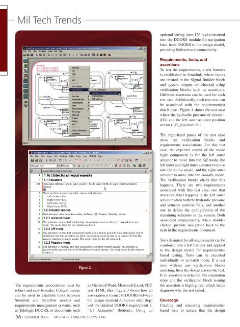
The requirements associations must be<br />
robust and easy to make. Context menus<br />
can be used to establish links between<br />
Simulink and Stateflow models and<br />
requirements-management systems, such<br />
as Telelogic DOORS, or documents such<br />
Figure 3<br />
38 / SUMMER <strong>2006</strong> MILITARY EMBEDDED SYSTEMS<br />
as Microsoft Word, Microsoft Excel, PDF,<br />
and HTML files. Figure 3 shows how an<br />
association is formed to DOORS between<br />
the design element Actuators state (top)<br />
and the detailed DOORS requirement 2,<br />
“1.1 Actuators” (bottom). Using an<br />
Tests designed for all requirements can be<br />
combined into a test harness and applied<br />
to the design model for requirementsbased<br />
testing. Tests can be executed<br />
individually or in batch mode. If a test<br />
runs without any verification blocks<br />
asserting, then the design passes the test.<br />
If an assertion is detected, the simulation<br />
stops and the verification block issuing<br />
the assertion is highlighted, which helps<br />
diagnose why the test failed.<br />
Coverage<br />
Creating and executing requirementsbased<br />
tests to ensure that the design