Military Embedded Systems Summer 2006
Military Embedded Systems Summer 2006
Military Embedded Systems Summer 2006

Create successful ePaper yourself
Turn your PDF publications into a flip-book with our unique Google optimized e-Paper software.
Mil Tech Trends<br />
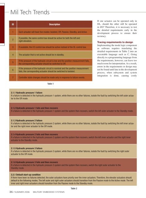
ID<br />
Description<br />
1 Each actuator will have five modes: Isolated, Off, Passive, Standby, and Active.<br />
2<br />
If possible, the same control law should be active for both the left and<br />
right elevators.<br />
3 If available, the I/O control law should be active instead of the DL control law.<br />
4 The actuator that is not active should be in standby.<br />
5<br />
6<br />
If the pressure of the hydraulic circuit is low and the position measurement fails,<br />
the corresponding actuator should be switched to Off.<br />
If the pressure of the hydraulic circuit is nominal and the position measurement<br />
fails, the corresponding actuator should be switched to Isolated.<br />
7 Controller state changes should be made only in response to failure events.<br />
If one actuator can be operated only in<br />
DL, should the other still be operated<br />
in I/O? Therefore, it is necessary to test<br />
the detailed requirements early in the<br />
development process to ensure their<br />
accuracy.<br />
Tracing requirements to design<br />
Implementing the mode logic component<br />
as software requires translating the<br />
detailed requirements in Table 2 into an<br />
executable language such as C. Going<br />
directly to a programming language from<br />
the requirements, however, can leave too<br />
much room for interpretation. As a result,<br />
errors in the requirements or design may<br />
not be found until late in the development<br />
process, when subsystem and system<br />
integration is done, causing costly<br />
Table 1<br />
2.1.1 Hydraulic pressure 1 failure<br />
If a failure is detected in the hydraulic pressure 1 system, while there are no other failures, isolate the fault by switching the left outer actuator<br />
to the Off mode.<br />
2.1.2 Hydraulic pressure 1 fails and then recovers<br />
If a failure is detected in the hydraulic pressure 1 system and the system then recovers, switch the left outer actuator to the Standby mode.<br />
2.1.3 Hydraulic pressure 2 failure<br />
If a failure is detected in the hydraulic pressure 2 system, while there are no other failures, isolate the fault by switching the left inner actuator<br />
and the right inner actuator to the Off mode.<br />
2.1.4 Hydraulic pressure 2 fails and then recovers<br />
If a failure is detected in the hydraulic pressure 2 system and the system then recovers, switch the left inner actuator and the right inner<br />
actuator to the Standby mode.<br />
2.1.5 Hydraulic pressure 3 failure<br />
If a failure is detected in the hydraulic pressure 3 system, while there are no other failures, isolate the fault by switching the right outer<br />
actuator to the Off mode.<br />
2.1.6 Hydraulic pressure 3 fails and then recovers<br />
If a failure is detected in the hydraulic pressure 3 system and the system then recovers, switch the right outer actuator to the<br />
Standby mode.<br />
2.2.1 Default start-up condition<br />
If there have been no failures detected, the outer actuators have priority over the inner actuators. Therefore, the elevator actuators should<br />
default to the following modes. The left outer and right outer actuators should transition from the Passive mode to the Active mode. The left<br />
inner and right inner actuators should transition from the Passive mode to the Standby mode.<br />
36 / SUMMER <strong>2006</strong> <strong>Military</strong> EMBEDDED SYSTEMS<br />
Table 2