Military Embedded Systems Summer 2006
Military Embedded Systems Summer 2006
Military Embedded Systems Summer 2006

You also want an ePaper? Increase the reach of your titles
YUMPU automatically turns print PDFs into web optimized ePapers that Google loves.
Hardware<br />
RECONFIGURABLE FPGAs<br />
dB<br />
For narrower output bandwidths, the maximum decimation<br />
factor is determined by the complexity (number of taps) of the<br />
FIR filter, which must perform at least as well as the channelizer<br />
filter in order to maintain that dynamic range of 75 dB. Choosing<br />
a reasonable number of multiplier/accumulator stages yields an<br />
FIR filter suitable for decimation factors from 4 to 39 in steps of 1.<br />
The number of filter taps is equal to 26 times the decimation<br />
factor of the filter.<br />
Since the channelizer decimation (256) and FIR filter decimation<br />
(4 to 39) multiply, the overall range of decimation range for<br />
the entire core is 1,024 to 9,984 in steps of 256. Each of these<br />
36 available decimation factors requires its own set of filter<br />
coefficients, which are stored in a table within the FPGA. For<br />
an input clock of Fs = 100 MHz, the range of output bandwidths<br />
using the default 80 percent filter characteristic is approximately<br />
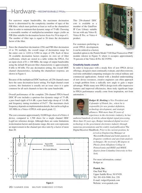
8 kHz to 80 kHz. For any decimation setting, the overall DDC<br />
channel characteristics, including the channelizer response, are<br />
shown in Figure 4.<br />
Because of the multiplexed DDC hardware, all 256 channels must<br />
have the same decimation factor setting. For high-channel count<br />
systems, this limitation is usually not an issue since it is quite<br />
common for all such channels to have the same bandwidth.<br />
Overall performance of the complete 256-channel FPGA-based<br />
DDC IP core includes a spurious-free dynamic range of 75 dB,<br />
a pass band ripple of 0.4 dB, a pass band edge droop of 1.0 dB,<br />
and frequency tuning resolution of Fs/2 32 . The maximum clock<br />
frequency depends on implementation details, but can be as high as<br />
185 MHz in a Virtex-4 FPGA with speed grade 12.<br />
The core consumes approximately 18,000 logic slices of a Virtex-4<br />
device, compared to 1,700 slices for a single channel DDC<br />
LogiCore reference design. Although there are some limitations<br />
in decimation factors and dynamic range, this new core represents<br />
an improvement in the channel-per-slice ratio by a factor of more<br />
than 20.<br />
-10<br />
-20<br />
-30<br />
-40<br />
-50<br />
-60<br />
-70<br />
-80<br />
-90<br />
0<br />
>75 dB<br />
SFDR<br />
0.4 dB<br />
PassBIN<br />
Ripple<br />
1.0 dB<br />
Edge<br />
Droop<br />
Nyquist BIN<br />
Fs / Decimation<br />
80% Usable BINwidth<br />
Figure 4<br />
20 / SUMMER <strong>2006</strong> MILITARY EMBEDDED SYSTEMS<br />
This 256-channel DDC<br />
core is available as a<br />
member of the GateFlow<br />
IP Core Library suitable<br />
for use with any Virtex-II,<br />
Virtex-II Pro, or Virtex-4<br />
product.<br />
For customers preferring to Figure 5<br />
avoid FPGA development,<br />
it can be ordered as a factory<br />
installed option to the Pentek Model 7140 Dual Transceiver PMC<br />
module (shown in Figure 5) where it occupies approximately<br />
76 percent of the Virtex-II Pro XC2VP50.<br />
Creativity beats crunch<br />
In order to keep pace with a steady flow of new FPGA device<br />
offerings, designers must continually evaluate, and often reinvent,<br />
real-time embedded computing strategies for critical military and<br />
commercial applications. Armed with a detailed understanding<br />
of new device resources, creative engineers can often approach<br />
a tough problem from a radically new angle to gain a major<br />
advantage. While many new FPGA design tools offer impressive<br />
features and improved efficiencies, these truly significant leaps<br />
in FPGA performance usually come from inspiration, not from<br />
automation.<br />
Rodger H. Hosking is Vice President and<br />
Cofounder of Pentek, Inc., where he is<br />
responsible for new product definition,<br />
technology development, and strategic<br />
alliances. With more than 30 years of<br />
experience in the electronics industry, he has<br />
authored hundreds of articles about digital signal processing.<br />
More than 10 years ago, Rodger introduced digital receiver<br />
technology to the government electronics industry through<br />
numerous presentations and his widely read publication The<br />
Digital Receiver Handbook. Prior to his current position, he<br />
served as Engineering Manager at<br />
Wavetek/Rockland and holds patents in<br />
frequency synthesis and spectrum analysis<br />
techniques. He received a BS degree in<br />
Physics from Allegheny College in<br />
Pennsylvania and BSEE and MSEE<br />
degrees from Columbia University in New<br />
York.<br />
For more information, contact<br />
Rodger at:<br />
Pentek, Inc.<br />
One Park Way<br />
Upper Saddle River, NJ 07458<br />
Tel: 201-818-5900, Ext. 228<br />
E-mail: rodger@pentek.com<br />
Website: www.pentek.com