Gate 1 24V Instructions - SEA (UK)
Gate 1 24V Instructions - SEA (UK)
Gate 1 24V Instructions - SEA (UK)

Create successful ePaper yourself
Turn your PDF publications into a flip-book with our unique Google optimized e-Paper software.
Sistemi elettronici<br />
GB<br />
di Aperture Porte e Cancelli<br />
<strong>SEA</strong> S.r.l.<br />
DIREZIONE E STABILIMENTO:<br />
Zona industriale 64020 S.ATTO Teramo - (ITALY)<br />
Tel. 0861 588341 r.a. Fax 0861 588344<br />
English<br />
http://www.seateam.com<br />
e-mail:seacom@seateam.com (Uff. Comm.le)<br />
seatec@seateam.com (Uff. Tecnico)<br />
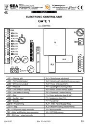
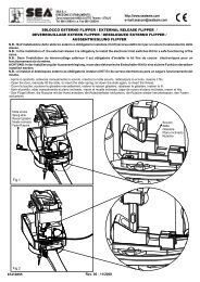
GATE 1 <strong>24V</strong> DC for VERG <strong>24V</strong><br />
CONTROL UNIT<br />
(cod. 23001130)<br />
1 2 3 4 5 6 7 8 9 10 1 2 3 4 5 6<br />
1 2 3<br />
CN3<br />
CN4<br />
P1<br />
CN2<br />
LED6<br />
LED1<br />
LED2<br />
Rv3<br />
DLE3<br />
LED4<br />
LED5<br />
F2<br />
LED9<br />
Rv1<br />
Rv2<br />
U1<br />
DIP<br />
CN6<br />
RL1<br />
RL2<br />
F1<br />
LED8<br />
LED7<br />
CN5<br />
CN1<br />
1 2 3 4<br />
LED1 = Photocell<br />
LED2 = Closes<br />
LED3 = Start<br />
LED4 = Stop<br />
LED5 = Timer / Opens<br />
LED6 = Safety edge<br />
LED7 = Encoder<br />
LED8 = Power supply<br />
LED9 = Programming<br />
CN1 = Transformer motor connector<br />
CN2 = Encoder connector<br />
CN3 = Inputs/outputs <strong>24V</strong> connector<br />
CN4 = Flashing lamps <strong>24V</strong> connector<br />
CN5 = Batterycharger connector (see last page)<br />
CN6 = Radio receiver connector<br />
Rv1 = Motor speed regulation<br />
Rv2 = Slow down speed regulation<br />
Rv3 = Anti-crushing sensibility regulation<br />
P1 = Working time memorizing push button<br />
DIP = Dip switch for functions setting<br />
F1 = Power supply and motor (10A) fuse<br />
F2 = Accessories fuse (2A)<br />
RL1 - RL2 = Relè motor direction<br />
U1 = Microcontroller<br />
67410616<br />
Rev 02 - 09/2005
0 V<br />
Sistemi elettronici<br />
24 Vdc<br />
Cl os e s<br />
STOP<br />
G re e n<br />
0V<br />
W hi t e<br />
Br o wn<br />
+ 5V<br />
di Aperture Porte e Cancelli<br />
<strong>SEA</strong> S.r.l.<br />
DIREZIONE E STABILIMENTO:<br />
Zona industriale 64020 S.ATTO Teramo - (ITALY)<br />
Tel. 0861 588341 r.a. Fax 0861 588344<br />
http://www.seateam.com<br />
e-mail:seacom@seateam.com (Uff. Comm.le)<br />
seatec@seateam.com (Uff. Tecnico)<br />
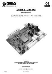
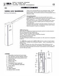
CONNECTIONS<br />
CN3<br />
CN4<br />
1 2 3 4 5 6 7 8 9 10<br />
1 2 3 4 5 6<br />
Not used<br />
Not used<br />
T ra ffic ligh t g r e e n /<br />
War nn i g Lam<br />
p<br />
2 4V 15 W max<br />
Traffic light red /<br />
Flashing Lamp<br />
ASTRT<br />
24 V 1 5W ma x<br />
C O MMO N<br />
C O MMO N<br />
Op en s / Ti me r<br />
Sa f et y Edge<br />
Ph o toce ll<br />
CN2 (ENCODER)<br />
DIP<br />
1 2 3<br />
ON<br />
ON= Working function<br />
1 2 3 4 5 6 7 8<br />
Working Logics<br />
Safety Reverser<br />
Not working<br />
Closing with Photocell<br />
Traffic light management<br />
Pre-flashing<br />
Programming<br />
Dat a (Signal)<br />
CN1<br />
1 2 3 4<br />
M<br />
67410616<br />
Rev 02 - 09/2005<br />
Transformer<br />
22Vac
Sistemi elettronici<br />
di Aperture Porte e Cancelli<br />
<strong>SEA</strong> S.r.l.<br />
DIREZIONE E STABILIMENTO:<br />
Zona industriale 64020 S.ATTO Teramo - (ITALY)<br />
Tel. 0861 588341 r.a. Fax 0861 588344<br />
http://www.seateam.com<br />
e-mail:seacom@seateam.com (Uff. Comm.le)<br />
seatec@seateam.com (Uff. Tecnico)<br />
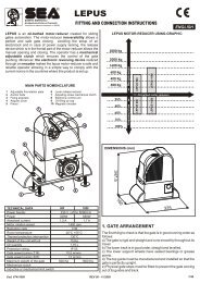
SETTING OF WORKING LOGICS<br />
ON<br />
1 2 1 2 1 2 1 2<br />
DEAD MAN LOGIC<br />
The automation functions by “Maintained” contacts acting on the entries of open and close.<br />
The entry “Open” commands the opening of the barrier. The entry “Close” the closing.<br />
HALF AUTOMATIC LOGIC<br />
The repeated start realizes the following sequence: open-stop-close- open-stop-close-......<br />
TWO PUSH BUTTON LOGIC<br />
One impulse on the command “Open” opens the barrier.<br />
One impulse on the command “Close” closes the barrier.<br />
AUTOMATIC LOGIC (automatic closing)<br />
The start executes only an opening when the barrier is closed, in opening it has no effect, in<br />
pause it closes immediately, in closing it re-opens.<br />
OTHER FUNCTIONS<br />
ON<br />
3<br />
INTERVENTION OF THE SAFETY REVERSER IN CLOSING<br />
OFF: It opens again and if the automatic closing is programmed after the pause time it closes.<br />
If the closing has not been completed after two attempts, the barrier remains opened and<br />
waits for commands.<br />
ON: It opens again and waits for commands.<br />
ON<br />
NOT WORKING<br />
4<br />
ON<br />
ON<br />
5<br />
6<br />
CLOSING FUNCTION AFTER THE INTERVENTION OF THE PHOTOCELL<br />
ON: If a pause time is programmed it is reduced to 0 seconds when the photocells are<br />
interrupted in opening or in pause.<br />
TRAFFIC LIGHT MANAGEMENT<br />
Traffic light management with red lamp has to be connected to the flashing light exit and the<br />
green lamp to the control lamp exit.<br />
The red signal is given when the barrier is closed, in opening and closing.<br />
The green signal is given when the barrier is open.<br />
67410616<br />
Rev 02 - 09/2005
Sistemi elettronici<br />
di Aperture Porte e Cancelli<br />
<strong>SEA</strong> S.r.l.<br />
DIREZIONE E STABILIMENTO:<br />
Zona industriale 64020 S.ATTO Teramo - (ITALY)<br />
Tel. 0861 588341 r.a. Fax 0861 588344<br />
http://www.seateam.com<br />
e-mail:seacom@seateam.com (Uff. Comm.le)<br />
seatec@seateam.com (Uff. Tecnico)<br />
ON<br />
7<br />
PRE-FLASHING<br />
OFF: The flashing lamp works together with the motor starting.<br />
ON: Pre-flashing which advances every movement of 3 sec. but the reversing, due to the<br />
intervention of the safeties.<br />
ON<br />
8<br />
PROGRAMMING<br />
OFF: Setting for Normal functioning.<br />
ON: It opens the time programming phase.<br />
INPUTS/OUTPUTS DESCRIPTION<br />
PHOTOCELL (N.C.)<br />
In closing when the signal is interrupted it immediately opens.<br />
STOP (N.C.)<br />
It stops the automation whenever it is pushed.<br />
A start order is necessary to reset the movement.<br />
START (N.O.)<br />
Input to command the automation depending on DIP1 and 2<br />
OPEN (N.O.)<br />
Commands the opening of the barrier depending on how Dip 1 and 2 have been set.<br />
CLOSE (N.O.)<br />
Commands the closing of the barrier depending on how Dip 1 and 2 have been set.<br />
TIMER (N.O.) (to use as clock input)<br />
Input of opening only. Keeping it in function with the Automatic Logic the automation does not close until when<br />
it is not obstructed.<br />
SAFETY EDGE (N.C.)<br />
If it is set up during the opening/closing phase, it stops the movement and reverses for about 0,5 sec.<br />
A start order is necessary to reset the movement.<br />
IMPORTANT NOTICE: All the N.C. contacts which are not used must be linked with common.<br />
FLASHING LAMP:<br />
During the opening phase, it flashes once a second; during the closing phase, it flashes twice a second.<br />
When the automation is opened and in automatic logic, the flashing lamp stays on for all the pause time.<br />
If DIP 7 is set on ON there will be a pre-flashing of 3 seconds before the barrier starts to move.<br />
If DIP 6 is set on ON, it manages the red signal of the traffic light.<br />
WARNING LAMP:<br />
Follows the same logic of the flashing light and remains switched on should the barrier stop and not be in<br />
closing position.<br />
When DIP 6 is set on ON, it manages the green signal of the traffic lamp.<br />
67410616<br />
Rev 02 - 09/2005
Sistemi elettronici<br />
di Aperture Porte e Cancelli<br />
<strong>SEA</strong> S.r.l.<br />
DIREZIONE E STABILIMENTO:<br />
Zona industriale 64020 S.ATTO Teramo - (ITALY)<br />
Tel. 0861 588341 r.a. Fax 0861 588344<br />
http://www.seateam.com<br />
e-mail:seacom@seateam.com (Uff. Comm.le)<br />
seatec@seateam.com (Uff. Tecnico)<br />
SETTINGS<br />
Rv1<br />
Rv2<br />
Rv3<br />
MOTOR SPEED REGULATION<br />
Trimmer completely turned anti-clockwise = low speed<br />
Trimmer completely turned clockwise = high speed<br />
NOTICE: Pay a lot of attention when adjusting the maximum functioning speed, as it must<br />
be adapted to the mechanical structure of the barrier and must respect the technical rules<br />
in force.<br />
Note: For the opening time follow the table in the mechanical manual.<br />
SLOW DOWN SPEED REGULATION<br />
Trimmer completely turned anti-clockwise = low speed<br />
Trimmer completely turned clockwise = high speed<br />
NOTICE: Pay a lot of attention when adjusting the maximum slow down speed, as it must<br />
be adapted to the mechanical structure of the barrier and must respect the technical rules<br />
in force.<br />
INTERVENTION THRESHOLD OF THE ANTI-CRUSHING DETECTOR REGULATION<br />
Trimmer completely turned anti-clockwise = high sensibility (low push in case of obstacle).<br />
Trimmer completely turned clockwise = low sensibility (high push in case of obstacle).<br />
After two consecutive interventions of the anti-crushing detector, even if in automatic logic, the<br />
automation stays opened waiting for orders.<br />
Regulate the sensibility in observance with the current laws.<br />
NOTICE: The setting of Trimmers and Dip Switches are read when the automation has stopped.<br />
P1<br />
It puts in action the autoprogramming process (with DIP 8 = ON)<br />
It puts in action the opening/closing of the automation (with DIP 8 = OFF)<br />
PROCESS OF CARD SELF-PROGRAMMING<br />
After having verified the correct movement of the barrier and the electrical connexions on the entries/exits,<br />
execute the following procedure:<br />
1. Release the barrier and bring it manually next to the stop in closure<br />
2. Restore the mechanical lock and move the barrier by hand until the mechanical plug in of the lock<br />
3. Give input to the <strong>Gate</strong> 1 <strong>24V</strong> card<br />
4. Bring Dip Switch 8 on ON position<br />
5. Make sure that during the learning process the stop, photocell, safety edge, etc. commands are not set up.<br />
6. Push button S1 (Make sure the barrier closes, on the contrary switch off the automation, reverse the motor<br />
cables (black and red) on CN1 and repeat the process from point 1)<br />
7. Once reduced the speed, the barrier will close until reaching the mechanical stop in closing<br />
8. At this point and once reduced the speed, it will automatically open.<br />
9. Once the opening phase has ended, the counting of the pause time will start.<br />
Wait for the desired time (every flash of the warning lamp is equivalent to about 1 sec.) and push P1 button<br />
again<br />
10. Wait for the complete closing of the barrier<br />
11. When the barrier will stop and will be completely closed, bring Dip Switch 8 on OFF position<br />
12. The automation is ready to work<br />
67410616<br />
Rev 02 - 09/2005
Sistemi elettronici<br />
di Aperture Porte e Cancelli<br />
<strong>SEA</strong> S.r.l.<br />
DIREZIONE E STABILIMENTO:<br />
Zona industriale 64020 S.ATTO Teramo - (ITALY)<br />
Tel. 0861 588341 r.a. Fax 0861 588344<br />
http://www.seateam.com<br />
e-mail:seacom@seateam.com (Uff. Comm.le)<br />
seatec@seateam.com (Uff. Tecnico)<br />
SAFETY PRECAUTIONS<br />
All electrical installation work should conform to current regulations.<br />
A 16A - 0,030A differential switch must be incorporated into the source of the gate main electrical supply and<br />
the entire system must be properly earth bonded.<br />
Remember to separate mains (230/115 V) carrying cables from low voltage control cables.<br />
SPARE PARTS<br />
To obtain spare parts contact:<br />
<strong>SEA</strong> s.r.l. ZONA Ind.le, 64020 S.ATTO Teramo Italia<br />
INTENDED USE<br />
The electronic control unit 23001130 has been planned to be used exclusively as a control device for sliding<br />
gates, swing gates, garage-doors, folding doors, barriers<br />
SAFETY AND ENVIRONMENTAL COMPATIBILITY<br />
We recommend not to spoil the environment with product and circuit packing material.<br />
STORAGE<br />
STORAGE TEMPERATURES<br />
T min T max Humidity min Humidity max<br />
-40 °C +85 °C 5% no condensation 90% no condensation<br />
When being transported this product must be properly packaged and handled with care.<br />
MAINTENANCE AND OUT OF SERVICE<br />
The decommission and maintenance of this unit must only be carried out by specialised and authorised<br />
personnel.<br />
LIMIT OF GUARANTEE<br />
The 23001130 electronic control units are guaranteed for a period of 24 months. The guarantee period starts<br />
from the date stamp printed on the unit. The 23001130 guarantee will be void if the unit has been incorrectly<br />
installed, not used for the purpose intended, tampered with or modified in any way.<br />
The validity of this guarantee only extends to the original purchaser of the unit.<br />
NOTE: THE MANUFACTURER CAN NOT BE DEEMED RESPONSIBLE FOR ANY DAMAGE OR INJURY<br />
CAUSED BY IMPROPER USE OF THIS PRODUCT.<br />
<strong>SEA</strong> reserves the right to do changes or variations that may be necessary to its products with no obligation to<br />
notice.<br />
67410616<br />
Rev 02 - 09/2005
Sistemi elettronici<br />
di Aperture Porte e Cancelli<br />
<strong>SEA</strong> S.r.l.<br />
DIREZIONE E STABILIMENTO:<br />
Zona industriale 64020 S.ATTO Teramo - (ITALY)<br />
Tel. 0861 588341 r.a. Fax 0861 588344<br />
http://www.seateam.com<br />
e-mail:seacom@seateam.com (Uff. Comm.le)<br />
seatec@seateam.com (Uff. Tecnico)<br />
CONNECTION OF BATTERIES AND BATTERYCHARGER CARD (OPTIONAL)<br />
GATE 1 <strong>24V</strong> CONTROL UNIT<br />
1 2 3 4<br />
CN5<br />
+<br />
-<br />
BATTERYCHARGER<br />
CARD<br />
1 2 3<br />
+<br />
-<br />
+<br />
-<br />
1 2 3 4 5 6 7 8 9 10 1 2 3 4 5 6<br />
12V<br />
2Ah min.<br />
Battery 1<br />
12V<br />
2Ah min.<br />
Battery 2<br />
67410616<br />
Rev 02 - 09/2005