Sage 1a Controller - Categories On Thermal Solutions Products LLC ...
Sage 1a Controller - Categories On Thermal Solutions Products LLC ...
Sage 1a Controller - Categories On Thermal Solutions Products LLC ...

Create successful ePaper yourself
Turn your PDF publications into a flip-book with our unique Google optimized e-Paper software.
Contents<br />
<strong>Thermal</strong> <strong>Solutions</strong><br />
Boiler Control<br />
(TSBC)<br />
Instruction Manual<br />
Introduction<br />
Quick Reference 2<br />
Overview 4<br />
Product Features<br />
Boiler Sequence 6<br />
Single Boiler Control Mode 9<br />
Multiple Boiler Control Mode 10<br />
EMS Boiler Control Mode 11<br />
Manual Boiler Control Mode 14<br />
Auxiliary Device 15<br />
Front Panel<br />
Features 16<br />
Display Mode 17<br />
Menu Navigation 18<br />
Setpoints Menu 19<br />
Installation<br />
Terminal Layout 20<br />
External Connections 21<br />
Communication 23<br />
Peer-To-Peer Network 25<br />
RS485 Modbus Network 26<br />
Setup & Tuning<br />
Boiler Configuration Menu 28<br />
System Configuration Menu 29<br />
Setup Menu 30<br />
Manual Mode 35<br />
Trouble Shooting<br />
Alarm Messages 36<br />
Diagnostics Menu 38<br />
Sensor Temperature vs. Resistance 41<br />
Security Menu 42<br />
Specifications<br />
General 43<br />
Component Description & Repair Part Numbers 44<br />
Appendix<br />
A. Parameter Summary 45<br />
B. Customer Parameter Worksheet 47<br />
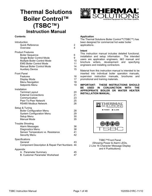
Application<br />
The <strong>Thermal</strong> <strong>Solutions</strong> Boiler Control(TSBC) has<br />
been designed for commercial hot water boiler<br />
applications.<br />
Intent<br />
This instruction manual includes detailed functional,<br />
installation and setup information. The intended<br />
users are application engineers, I&O manual and<br />
brochure writers, development and specifying<br />
engineers and installing contractors.<br />
Material from this instruction manual is intended to be<br />
inserted into individual boiler operation manuals,<br />
supervisor instruction manuals, brochures and<br />
promotional and training materials.<br />
IMPORTANT: THESE INSTRUCTIONS SHOULD<br />
BE USED IN CONJUNCTION WITH THE<br />
APPROPRIATE BOILER OR WATER HEATER<br />
INSTALLATION MANUAL.<br />
TSBCFront Panel<br />
(Showing Power & Alarm LEDs,<br />
2 Line 16 Character Message Display<br />
and 4 Pushbuttons)<br />
TSBC Instruction Manual Page 1 of 48 102059-01RC-11/10
Introduction<br />
Quick Reference<br />
CONTROL<br />
MODE<br />
LCD Display<br />
Outlet Sensor<br />
& Local SP<br />
Mode<br />
Remote Sensor<br />
& Local SP Mode<br />
Outlet Sensor &<br />
Remote SP<br />
Mode<br />
Remote Sensor<br />
& Remote SP<br />
Mode<br />
Remote<br />
Control<br />
Mode<br />
Manual<br />
Mode<br />
Typical<br />
Application<br />
Water Setpoint<br />
Temperature<br />
Sensor<br />
Energy Management System (EMS) Boiler Control<br />
Single Boiler Multiple Boilers Single Boiler Multiple Boilers Modulation<br />
Setpoint Input Setpoint Input Rate Input<br />
Manual<br />
Operation<br />
Boiler Outlet Remote System Boiler Outlet Remote System Ignored Ignored<br />
Setpoint Operator Operator<br />
“<strong>On</strong>” and “Off”<br />
Point<br />
Outdoor Air<br />
Reset<br />
Domestic Hot<br />
Water Priority<br />
(DHWP)<br />
Warm Weather<br />
Shutdown<br />
(WWSD)<br />
Input (C+C-) or<br />
Modbus*<br />
Input (C+C-) or<br />
Modbus*<br />
Ignored<br />
Ignored<br />
Operator Operator Operator Operator Ignored Ignored<br />
Option Option Ignored Ignored Ignored Ignored<br />
Option Option Ignored Ignored Ignored Ignored<br />
Option Option Option Option Option Ignored<br />
Call For Heat<br />
Call For Heat<br />
Modulation<br />
Rate<br />
Internal Boiler<br />
Control<br />
Lead Boiler<br />
Control<br />
Remote EMS<br />
Control<br />
Manual<br />
Control<br />
Remote<br />
Connections<br />
Local / Remote<br />
Input (LR)<br />
Based on<br />
Setpoints<br />
Based on<br />
Setpoint<br />
Peer-to-Peer<br />
Connected<br />
Based on<br />
Setpoints<br />
Based on<br />
Setpoint<br />
With Peer-to-<br />
Peer Connected<br />
Based on<br />
Setpoints<br />
Based on<br />
Setpoint<br />
With Peer-to-<br />
Peer Connected<br />
Based on<br />
Setpoints<br />
Based on<br />
Setpoint<br />
With Peer-to-<br />
Peer Connected<br />
Ignored Ignored Ignored Ignored<br />
Input (RO) or<br />
Modbus<br />
Ignored<br />
Ignored<br />
Input (C+C-)<br />
or Modbus<br />
Manually Set<br />
Ignored<br />
Ignored<br />
Ignored<br />
Ignored Ignored Ignored Ignored Ignored By Operator<br />
Ignored Ignored Closed Closed Closed Ignored<br />
Remote <strong>On</strong>/Off<br />
(Enable)<br />
Input (RO)<br />
Remote Control<br />
Input (C+C-)<br />
Communication<br />
Network<br />
Enable/<br />
Disable<br />
No<br />
Peer-To-Peer<br />
or<br />
Modbus*<br />
Enable/<br />
Disable<br />
No<br />
Peer-To-Peer<br />
or<br />
Modbus*<br />
Enable/<br />
Disable<br />
Remote<br />
Setpoint<br />
Peer-To-Peer<br />
or<br />
Modbus*<br />
Enable/<br />
Disable<br />
Remote<br />
Setpoint<br />
Peer-To-Peer<br />
or<br />
Modbus*<br />
<strong>On</strong>/Off<br />
Remote<br />
Modulation<br />
Modbus<br />
<strong>On</strong>ly<br />
Ignored<br />
Ignored<br />
Modbus <strong>On</strong>ly<br />
Additional<br />
Page 9 Page 10 Page 11 Page 12 Page 13 Page 14<br />
Information<br />
* If Modbus is selected the Peer-To-Peer Network can not be used. Modulating Lead/Lag features require the Peer-To-<br />
Peer Network.<br />
TSBC Instruction Manual Page 2 of 48
Introduction<br />
Quick Reference<br />
Abbreviation List<br />
Abbreviation<br />
AL<br />
BIT<br />
BOT<br />
BP<br />
BV<br />
C<br />
CA<br />
CH<br />
CS<br />
DH<br />
DP<br />
TSBC<br />
EMS<br />
GP<br />
HL<br />
HP<br />
IN<br />
LC<br />
LL<br />
LO<br />
LR<br />
M<br />
Mix<br />
OA<br />
OL<br />
OO<br />
OUT<br />
RO<br />
RST<br />
SH<br />
SI<br />
SO<br />
SP<br />
SP<br />
VI<br />
WF<br />
WWSD<br />
Description<br />
Flame Safeguard Alarm<br />
Boiler Inlet Temperature<br />
Boiler Outlet Temperature<br />
Boiler Pump<br />
Blocked Vent Switch<br />
Common Termination Point<br />
Low Combustion Air Flow<br />
Call For Heat (CFH)<br />
Fuel Valve Energized<br />
Domestic Hot Water Heating Demand<br />
Domestic Hot Water Priority (DHWP)<br />
<strong>Sage</strong> Boiler Control<br />
Energy Management System<br />
High and Low Gas Pressure Switches<br />
High Limit Aquastat<br />
High Pressure Gas Switch<br />
Boiler Inlet Water Temperature<br />
Low Water Cutoff Switch<br />
Lead Lag<br />
Lockout Indicator<br />
Local / Remote<br />
Electric Motor<br />
3 Way Mixing Valve<br />
Outside Air Temperature<br />
Operating Limit Aquastat<br />
Burner <strong>On</strong> / Off Switch<br />
Boiler Outlet Water Temperature<br />
Remote <strong>On</strong> / Off<br />
Remote System Temperature<br />
Space Heating Demand<br />
Spare Input (Programmable)<br />
Spare Output (Programmable)<br />
Setpoint (As found in “Operational SP” and “Remote SP”<br />
System Pump<br />
Vent Inducer<br />
Low Water Flow<br />
Warm Weather Shutdown<br />
Termination Number Identification (Typical):<br />
Description<br />
Mixing Valve<br />
Control, (MR, MS)<br />
Termination<br />
Numbers<br />
TSBC Instruction Manual Page 3 of 48
Introduction<br />
Overview<br />
<strong>Thermal</strong> <strong>Solutions</strong> Boiler Control Overview<br />
The <strong>Thermal</strong> <strong>Solutions</strong> Boiler Control (TSBC) is a complete boiler monitoring and automation system. The TSBC provides<br />
advanced boiler modulation, operating control, diagnostics, multiple boiler lead-lag and auxiliary device control. The TSBC<br />
provides advanced control features in an easy to use package.<br />
Flexible, Field Selectable Control<br />
Control modes, water system, boiler auxiliary and<br />
modulating lead/lag control features are menu selectable<br />
without the need for external programmers, laptops or<br />
down loads. Every boiler is shipped with factory defaults<br />
that make field menu selections unnecessary unless you<br />
are applying additional control features.<br />
Boiler Monitoring and Diagnostic Displays<br />
The TSBC’s two line by sixteen character LCD display<br />
may be used for monitoring boiler inlet and outlet,<br />
remote system and outside air temperatures, modulation<br />
rate setpoint and modulating percent and mixing valve<br />
demand percent. Additionally, the display automatically<br />
presents boiler sequence messages, alarms, hold and<br />
lockout messages. A diagnostic menu is included that<br />
provides the last 10 alarm messages and boiler inlet<br />
temperature alarm history. Boiler inlet temperature<br />
alarm history includes time and date, the lowest inlet<br />
temperature reached and the amount of time the water<br />
temperature dropped below the alarm setpoint.<br />
Modulation Rate and <strong>On</strong>/Off Modes<br />
The TSBC may simply control boiler modulation and<br />
on/off output based on the boiler water outlet<br />
temperature and an operator adjusted setpoint.<br />
However, using parameter selections, the TSBC allows<br />
the boiler modulation and on/off output to respond to<br />
remote system water and outside air temperatures,<br />
Domestic Hot Water Priority (DHWP) input or Energy<br />
Management System (EMS) modulation rate demand,<br />
remote setpoint or remote start/stop commands.<br />
Parameter selections of remote system water<br />
temperature and remote mode determine the choice of<br />
one of six different control modes.<br />
Advanced Availability<br />
The above control modes are menu selectable options.<br />
However, if a selected sensor fails, the TSBC<br />
automatically changes to a control mode that will allow<br />
continued automatic operation of the boiler. For<br />
example, in the event of a remote system temperature<br />
sensor failure, the TSBC will automatically switch to<br />
boiler outlet temperature sensor based control.<br />
Outdoor Air Reset<br />
When selected the modulation rate setpoint is<br />
automatically adjusted based on outside air temperature.<br />
Outdoor air “reset” setpoint saves fuel by adjusting the<br />
water temperature of a heating boiler lower as the<br />
outside air temperature increases.<br />
Warm Weather Shutdown (WWSD)<br />
Some boilers are used primarily for heating buildings,<br />
and the boilers can be automatically shutdown when the<br />
outdoor air temperature is warm. When outside air<br />
temperature is above the WWSD setpoint, this function<br />
will prevent the boiler, boiler pump and/or the system<br />
pump from starting.<br />
Domestic Hot Water Priority (DHWP)<br />
Some boilers are used primarily for building space<br />
heating, but also provide heat for the domestic hot water<br />
users. When the outdoor temperature is warm, the<br />
outdoor reset setpoint may drop lower than a desirable<br />
domestic hot water temperature. When enabled and a<br />
DHWP contact input is detected, the hot water setpoint<br />
is adjusted to be greater than a field adjustable DHWP<br />
Setpoint.<br />
Water Side Control Outputs<br />
In order to maximize the life and availability of a hot<br />
water systems it may be desirable to automate mixing<br />
valves, boiler pumps, system pumps, and standby<br />
system pumps. The TSBC makes this type of<br />
automation totally integrated and cost effective. The<br />
control of these devices is field selectable through<br />
simple yes/no menu selections.<br />
Combustion Air Side Control Outputs<br />
Boiler room Combustion air dampers (fresh air dampers)<br />
and Vent Inducer control outputs are field selectable<br />
options.<br />
Peer-To-Peer Network<br />
The TSBC includes state-of-the-art modulating lead-lag<br />
sequencer for up to eight (8) boilers capable of auto<br />
rotation, outdoor reset and peer-to-peer communication.<br />
The peer-peer network is truly “plug and play”.<br />
Communication is activated by simply connecting a<br />
RJ11 telephone line between boilers. The TSBC<br />
provides precise boiler coordination by sequencing<br />
boilers based on both remote system water temperature<br />
and boiler modulation rate. For example, the lead boiler<br />
can be configured to start a lag boiler after operating<br />
above 90% modulation rate for longer than an adjustable<br />
time. The boilers are modulated in “unison” (parallel)<br />
modulation rate to ensure even heat distribution<br />
Modbus Communication Interface<br />
A factory configured RS485 Modbus interface is<br />
available for Energy Management System (EMS) or<br />
SCADA system monitoring and control.<br />
TSBC Instruction Manual Page 4 of 48
Introduction<br />
Overview<br />
Fresh Air<br />
Supply<br />
Return Water<br />
Outside Air<br />
Temperature<br />
M<br />
Combustion Air<br />
Damper<br />
Boiler<br />
Jacket<br />
Boiler <strong>On</strong>/Off<br />
Switch<br />
Boiler Inlet Temperature<br />
Combustion<br />
Air Flow<br />
Switch<br />
FAN<br />
Modutrol Motor<br />
Control<br />
POWER<br />
ALARM<br />
Fuel<br />
Supply<br />
Fuel Switches<br />
Boiler Running<br />
<strong>Thermal</strong> <strong>Solutions</strong> Boiler Control<br />
Standby System Pump<br />
System Pump<br />
Feedback<br />
System Pump<br />
M<br />
Mixing Valve<br />
Control<br />
Boiler Pump<br />
Low Water Flow Switch<br />
Low Water Cutoff Switch<br />
High Temperature Limit<br />
Boiler Outlet Temperature<br />
Spare Output<br />
Call For Heat Relay<br />
Fuel Valve Energized<br />
Alarm (Lockout)<br />
Low Fire<br />
Primary<br />
Control<br />
Remote System<br />
Temperature<br />
Domestic Hot<br />
Water Override<br />
Switch<br />
System<br />
Supply Water<br />
Domestic<br />
Hot Water<br />
Supply<br />
Building Automation<br />
System<br />
Lockout Indicator<br />
Remote Firing Rate or Setpoint<br />
Remote <strong>On</strong> / Off (Enable)<br />
Local / Remote Switch<br />
Modbus RS-485, RJ-11<br />
Connection<br />
TSBC Instruction Manual Page 5 of 48
Boiler Sequence<br />
Pre-Sequence States<br />
Product Features<br />
Start/Stop Sequence States<br />
BOILER STATE<br />
LCD Display<br />
Terminal Number<br />
Parameter/Note<br />
Boiler Disable<br />
Warm Weather<br />
Shutdown<br />
Lockout<br />
Standby<br />
Pump Purge<br />
Limit Hold<br />
Purge / Pilot Ignition<br />
Low Fire / Ignition<br />
Main Ignition<br />
Low Fire Hold<br />
Boiler Running<br />
Fan Post Purge<br />
Pump Cooldown<br />
Parameter / Notes<br />
a<br />
b &c<br />
a<br />
a<br />
3/d - - - - 53 - 54/d 4/d<br />
Boiler Disable or Remote <strong>On</strong>/Off RO -<br />
Boiler Enable/Disable <strong>On</strong><br />
Outdoor Air Temp ><br />
Warm Weather Shutdown Setpoint<br />
O+,O-<br />
44,30,<br />
75<br />
Limits<br />
Relay Outputs Interlock Inputs<br />
Inputs<br />
Domestic Hot Water Priority<br />
Low Fire Hold<br />
Fuel Valve Energized<br />
Flame Safeguard Alarm<br />
System Pump Feedback<br />
Call For Heat<br />
Recycling Limits<br />
(LC, OO, WF, GP and HL inputs)<br />
Non-Recycling Limits<br />
(Combustion Air Flow (CA Input))<br />
Call For Heat Relay<br />
Lockout Indicator<br />
(Manual Reset Required)<br />
Spare Output<br />
Boiler Pump<br />
System Pump<br />
System Pump Backup Pump<br />
DP<br />
SI<br />
CS<br />
AL<br />
SI<br />
R+,R-<br />
OR<br />
BO,BC<br />
LC , OO ,WF,<br />
GP,HL<br />
CA<br />
CH<br />
VI<br />
BP<br />
20,74<br />
9<br />
-<br />
-<br />
9<br />
70,71,<br />
72<br />
8,27,<br />
28<br />
-<br />
-<br />
LO -<br />
-<br />
2,30<br />
SP 25,30<br />
SO 10<br />
Domestic Hot Water Demand Monitored<br />
System Pump Feedback Monitored<br />
Call For Heat<br />
Recycling Limits Made<br />
Non-Recycling Limits Made<br />
Call For Heat Relay <strong>On</strong><br />
Spare Output <strong>On</strong><br />
Boiler Pump <strong>On</strong><br />
System Pump <strong>On</strong><br />
Starts in response to System Pump Feedback Input SI<br />
Combustion Air Damper<br />
System Alarm<br />
SO<br />
10,27/<br />
e<br />
SO 10<br />
Combustion Air Damper Open<br />
Alarm Status is Monitored<br />
Modulation Outputs<br />
Firing Rate<br />
Mixing Valve Output<br />
Blower High Speed<br />
Purge %<br />
Modulation<br />
Low Fire %<br />
Blower 0 Volts<br />
MS,MR<br />
V+,V-,<br />
P+,P-<br />
V+,V-,<br />
P+,P-<br />
V+,V-,<br />
P+,P-<br />
V+,V-,<br />
P+,P-<br />
V+,V-,<br />
P+,P-<br />
TSBC Instruction Manual Page 6 of 48<br />
6,79,<br />
80<br />
49<br />
52<br />
-<br />
9,51/f<br />
50<br />
Modulate<br />
Notes<br />
a. Boiler Pump is “<strong>On</strong>” when the Boiler Pump is set to “<strong>On</strong> Always” or the boiler is lead boiler and Boiler Pump is set to “<strong>On</strong> Lead”.<br />
b. Boiler Pump is "<strong>On</strong>" when the Boiler Pump is set to "<strong>On</strong> Always" and WWSD is set to "WWSD of System Pump" or “Off”.<br />
c. System Pump is "<strong>On</strong>" when the System Pump is set to “yes” and WWSD is set to either "WWSD of Boiler" or "Off".<br />
d. Boiler pump is "<strong>On</strong>" during Prepurge and Post Purge when Boiler Pump is set to "Purge" or boiler is lead & Boiler Pump is set to “<strong>On</strong> Lead”.<br />
e. Combustion Air Damper Spare Output is maintained “<strong>On</strong>” for 2 minutes after the Call For Heat is removed.<br />
f. Modulation rate is held at purge % when low fire input is not provided.
Product Features<br />
Boiler Sequence (Continued)<br />
Pre-Sequence States<br />
BOILER<br />
STATE<br />
LCD Display<br />
Boiler<br />
Disabled<br />
Warm<br />
Weather<br />
Shutdown<br />
Lockout<br />
Standby<br />
CONTROL MODE<br />
LCD Display<br />
Any Mode<br />
(Except for<br />
Remote Control)<br />
Any Mode<br />
(Except for<br />
Manual Mode)<br />
Any Mode<br />
Outlet Sensor &<br />
Local SP Mode<br />
Remote Sensor<br />
& Local SP<br />
Mode<br />
Outlet Sensor &<br />
Remote SP<br />
Mode<br />
Remote Sensor<br />
& Remote SP<br />
Mode<br />
Remote Control<br />
Mode<br />
Manual<br />
Operation Mode<br />
Start/Stop Sequence States<br />
BOILER<br />
CONTROL MODE<br />
STATE<br />
LCD Display<br />
LCD Display<br />
Pump Purge<br />
Limit Hold<br />
Purge / Pilot<br />
Ignition<br />
Low Fire /<br />
Ignition<br />
Main Ignition<br />
Low Fire<br />
Hold<br />
Boiler<br />
Running<br />
Fan Post<br />
Purge<br />
Pump<br />
Cooldown<br />
Any Mode<br />
(Except<br />
Manual Mode)<br />
Any Mode<br />
Any Mode<br />
Any Mode<br />
Any Mode<br />
Any Mode<br />
Any Mode<br />
Any Mode<br />
Any Mode<br />
Description<br />
Boiler is prevented from starting, Remote <strong>On</strong>/Off (Enable) (Terminal RO) Input is not<br />
energized.<br />
Boiler is prevented from starting, Warm Weather Shutdown (WWSD) is enabled and<br />
outside air temperature is above the WWSD Setpoint.<br />
Boiler is prevented from starting, Flame Safeguard lockout is present. A Flame<br />
Safeguard manual reset is required.<br />
Control monitors boiler outlet temperature, a Call For Heat is initiated when boiler<br />
outlet temperature is below the Operational Setpoint.<br />
Control monitors Remote System Temperature, a Call For Heat is initiated when<br />
Remote System Temperature is below the Operational Setpoint.<br />
Control monitors boiler outlet temperature, a Call For Heat is initiated when boiler<br />
outlet temperature is below the Remote Setpoint Input (Terminal C+,C- or Modbus<br />
Interface).<br />
Control monitors Remote System Temperature, a Call For Heat is initiated when<br />
Remote System Temperature is below the Remote Setpoint Input (terminal C+,C- or<br />
Modbus Interface).<br />
Control monitors Remote <strong>On</strong>/Off (Enable) input (Terminal RO or Modbus Interface), a<br />
Call For Heat is initiated when input is energized.<br />
A Call For Heat is initiated when Manual Mode Menu item Boiler <strong>On</strong>/Off is set to <strong>On</strong>.<br />
Description<br />
<strong>On</strong>ce a Call For Heat is initiated and Boiler Pump Purge is selected, the pump output<br />
is energized until the Pump Prepurge Time is complete. If the Call For Heat condition<br />
still exists at the end of the Prepurge Time (the temperature of the water at the sensor<br />
may rise with boiler water flowing passed it) the pump will continue to operate and the<br />
Call For Heat Relay is energized.<br />
Power is applied to the safety limit string. If any limits does not pass power (is not<br />
energized), the alarm LED and LCD display shows the reason the start sequence is<br />
on Hold. Refer to Trouble shooting section for explanation of individual lockout and<br />
alarm messages.<br />
After the limit string passes power, the fan is started, the modulation output is set to<br />
Purge Rate. When the purge period is complete, the flame safeguard sequences on<br />
the ignition transformer and pilot.<br />
When the Spare Input Low Fire is selected, modulation output is set to the Low Fire<br />
Speed when the Spare Input is energized.<br />
The main gas valve input is energized and the modulation output is held constant for<br />
an ignition stabilization period.<br />
The modulation output is held at the Low Fire for the Low Fire Hold time.<br />
When this Low Fire Hold time is complete, the modulation output is released to<br />
modulate.<br />
When water temperature is above setpoint, there is a Flame Safeguard or Limit fault,<br />
the Call For Heat is ended and the modulating output is set to Purge Rate for the Post<br />
Purge Time.<br />
When Boiler Pump Purge is selected, the boiler pump remains “on” until the boiler<br />
outlet temperature is less than the Post Purge Delta (default is 5 F) above the Boiler<br />
Inlet Temperature.<br />
TSBC Instruction Manual Page 7 of 48
Product Features<br />
Boiler Sequence (Continued)<br />
Multiple Boilers<br />
Setpoint<br />
SYSTEM<br />
TEMPERATURE<br />
185<br />
180<br />
175<br />
1<br />
2<br />
5<br />
High Fire Limit<br />
(Parameter 37)<br />
BOILER<br />
FIRING RATE<br />
100<br />
50<br />
2<br />
3<br />
4<br />
4 5<br />
0<br />
PLANT LOAD<br />
(# BOILERS REQURED)<br />
3<br />
2<br />
1<br />
0<br />
Start<br />
Lead Boiler<br />
Fast<br />
Load<br />
Change<br />
Start<br />
1 st Lag<br />
Slow<br />
Load<br />
Change<br />
Start<br />
2 nd Lag<br />
Stop<br />
2 nd Lag<br />
Stop<br />
1 st Lag<br />
Stop<br />
Lead Boiler<br />
1<br />
2<br />
3<br />
4<br />
Boiler Start and Stop Peer-To-Peer Network Sequence Diagram<br />
(3 boiler system shown, typical for up to 8 boilers)<br />
- Lead Boiler Start<br />
Water temperature is below the setpoint by more than the “<strong>On</strong> Point” differential.<br />
- Temperature Based Lag Boiler Start<br />
Water temperature is below the setpoint by more than the “<strong>On</strong> Point” differential for longer than the adjustable<br />
time delay (“Boiler <strong>On</strong> Delay” parameter).<br />
- Modulation % Based Lag Boiler Start<br />
The boiler modulation rate has been above the adjustable limit (“LL Start Trigger” parameter) for longer than the<br />
time delay.<br />
- Lag Boiler Stop<br />
The boiler modulation rate has been below the adjustable limit (“LL Stop Trigger” parameter) for longer than the<br />
time delay. Additionally, lag boilers are stopped when water temperature is above the setpoint by more than the<br />
“Off Point” differential for longer than the “Boiler Off Delay” parameter).<br />
5<br />
- Lead Boiler Stop<br />
The last boiler remains on line until the water temperature is above the “Off Point” setpoint for longer than the<br />
time delay.<br />
Notes<br />
- The “Boiler Address” parameter assignment determines the boiler sequencing order.<br />
- The Lead Boiler automatically rotates (when “Rotate” parameter is enabled) based on field adjusted time<br />
(“Rotate After” parameter, default is 168 hours). When rotating, the lead boiler will move to the end of the lag<br />
order and the 1 st lag boiler will become the lead. The rest of the boilers will then move up in the lag order<br />
accordingly.<br />
- Lead Boiler is the first boiler to turn on and the last boiler to turn off, (First <strong>On</strong>, Last Off, FOLO).<br />
- Lag Boilers are turned on in order and turned off in reverse order, (First <strong>On</strong>, Last Off, FOLO).<br />
- Tripped boilers are replaced without waiting for the Boiler <strong>On</strong> Delay timer. If a tripped boiler becomes available it<br />
is returned to service.<br />
TSBC Instruction Manual Page 8 of 48
Product Features<br />
Single Boiler Control<br />
Display Shows: Outlet Sensor & Local SP Mode<br />
Return<br />
Water<br />
Outside Air<br />
Temperature<br />
( O + , O - )<br />
Boiler<br />
Circulator<br />
Boiler Outlet<br />
Temperature<br />
( BO , BC )<br />
POWER<br />
Boiler Inlet<br />
Temperature<br />
(BI, BC)<br />
EMS System Hardwired Connections<br />
Lockout Indicator ( LO )<br />
Soft Alarm (SO)<br />
Remote <strong>On</strong> / Off ( Enable ) ( RO)<br />
RJ11, RS-485 Communication<br />
System<br />
Circulator<br />
DHW<br />
Override<br />
Switch ( DP )<br />
Peer-To-Peer Network<br />
for Modulating Lead / Lag<br />
Or<br />
Modbus Network<br />
for Touch Screen or EMS Monitoring<br />
System<br />
Supply Water<br />
Domestic Hot<br />
Water ( DHW )<br />
Supply<br />
Outlet Sensor & Local SP Mode Application Diagram<br />
(Showing Relevant Connections)<br />
Features<br />
Setpoints<br />
The operator selects the setpoint and on and off points<br />
from the LCD display.<br />
Modulation Rate Control<br />
Boiler automatically modulates to maintain the boiler<br />
outlet temperature at setpoint.<br />
Call for Heat<br />
The Call For Heat is determined by the setpoint, on<br />
and off points and boiler outlet temperature.<br />
Options<br />
Outside Air Reset<br />
If enabled, the Outside Air Sensor will automatically<br />
adjusted the setpoint.<br />
Warm Weather Shutdown (WWSD)<br />
If enabled, the WWSD will disable a boiler start when<br />
outside air temperature is above a Warm Weather<br />
Shutdown (WWSD) setpoint.<br />
Domestic Hot Water Priority (DHWP)<br />
If enabled, the DHWP will adjust the setpoint to satisfy<br />
the DHWP setpoint when a DHWP input (DP) is<br />
energized.<br />
Selecting This Control Mode<br />
To select Outlet Sensor & Local SP Mode set the following<br />
parameters:<br />
System Configuration Menu:<br />
Remote Control = “No”<br />
Remote System Temperature Sensor = “No”<br />
Remote <strong>On</strong> / Off (Enable) Input (RO) = Closed (Jumper (RO)<br />
to (C) )<br />
If the Remote <strong>On</strong> / Off (Enable) (RO) input is opened, the Call<br />
For Heat Relay (CH) is de-energized.<br />
Modbus Network<br />
To establish a Modbus network set the following parameters:<br />
Communication Menu:<br />
Protocol = Modbus<br />
Modbus Address = Give each boiler a unique address.<br />
Baud Rate = Set identical to remote system.<br />
Parity = Set identical to remote system.<br />
Connect all boilers using a RJ11 ended telephone cable.<br />
If the Modbus network is activated the remote system may<br />
monitor and/or control boiler operation. Refer to page 26 for<br />
additional information.<br />
TSBC Instruction Manual Page 9 of 48
Product Features<br />
Multiple Boiler Control<br />
Display Shows: Remote Sensor & Local SP Mode<br />
Return<br />
Water<br />
Outside Air<br />
Temperature<br />
( O + , O - ) Boiler<br />
Circulator<br />
Remote System<br />
Temperature<br />
( R + , R - )<br />
Boiler Outlet<br />
Temperature<br />
( BO , BC )<br />
POWER<br />
ALARM<br />
Boiler Running<br />
Boiler<br />
Circulator<br />
Boiler Inlet<br />
Temperature<br />
(BI, BC)<br />
POWER<br />
ALARM<br />
Boiler Running<br />
Wired to Each<br />
TSBC controller<br />
Boiler<br />
Circulator<br />
POWER<br />
ALARM<br />
Boiler Running<br />
EMS System Hardwired<br />
Connections<br />
Lockout Indicator (LO)<br />
Soft Alarm ( SO )<br />
Remote <strong>On</strong> / Off (Enable) (RO)<br />
Remote System<br />
Temperature<br />
( R + , R-)<br />
Outside Air<br />
Temperature<br />
( O + , O-)<br />
Connects to<br />
Up to Eight<br />
Boilers<br />
System<br />
Circulator<br />
DHW Override<br />
Switch ( DP)<br />
RJ11, RS 485<br />
Peer to Peer<br />
Network<br />
Domestic Hot<br />
Water Priority<br />
(DP)<br />
System<br />
Supply Water<br />
Domestic Hot Water<br />
( DHW ) Supply<br />
Remote Sensor & Local SP Mode Application Diagram<br />
(Showing relevant connections for 3 boilers, typical for up to 8)<br />
Features<br />
Setpoints<br />
The operator selects the setpoint and on and off points<br />
from the LCD display.<br />
Modulation Rate Control<br />
Boiler automatically modulates to maintain the Remote<br />
System Temperature (RST) at setpoint.<br />
Call for Heat<br />
The Call for Heat is determined by setpoint, on and off<br />
points and RST. If a Peer-To-Peer network is activated, a<br />
Call for Heat is also initiated when the Lead boiler<br />
modulation rate % is above an adjustable High Fire Rate<br />
Limit (parameter 37) for too long a time.<br />
Options<br />
Outside Air Reset<br />
If enabled, the Outside Air Sensor will automatically<br />
adjusted the setpoint.<br />
Warm Weather Shutdown (WWSD)<br />
If enabled, the WWSD will disable a boiler start when<br />
temperature is above a Warm Weather Shutdown (WWSD)<br />
setpoint.<br />
Domestic Hot Water Priority (DHWP)<br />
If enabled, the DHWP will adjust the setpoint to satisfy the<br />
DHWP setpoint when a DHWP contact input (DP) is<br />
closed. When multiple boilers monitor the DHWP input, an<br />
isolated contact is required for each boiler.<br />
Selecting This Control Mode<br />
To select Remote Sensor & Local SP Mode set the<br />
following parameters:<br />
System Configuration Menu:<br />
Remote Control = “No”<br />
Remote System Temperature Sensor = Control<br />
Remote <strong>On</strong> / Off (Enable) Input (RO) = Closed (Jumper<br />
(RO) to (C) )<br />
If the Remote <strong>On</strong> / Off (Enable) (RO) input is opened, the<br />
Call For Heat Relay (CH) is de-energized.<br />
If the Remote System Temperature Sensor (RST) fails, the<br />
control mode is automatically switched to Outlet Sensor &<br />
Local SP Mode.<br />
Peer-To-Peer Network<br />
To establish a Peer-To-Peer network follow the procedure<br />
provided on page 25.<br />
If the Peer-To-Peer network is activated the Lead boiler<br />
controls modulation rate and Call for Heat for all networked<br />
boilers. Up to 8 networked boilers are fired in “Unison” (all<br />
at the same modulation rate).<br />
TSBC Instruction Manual Page 10 of 48
Product Features<br />
Energy Management System (EMS) Boiler Control<br />
Display Shows: Outlet Sensor & Remote SP Mode<br />
Return<br />
Water<br />
Outside Air<br />
Temperature<br />
( O + , O - )<br />
Boiler<br />
Circulator<br />
Boiler Outlet<br />
Temperature<br />
( BO , BC )<br />
POWER<br />
ALARM<br />
Boiler Inlet<br />
Temperature<br />
(BI, BC)<br />
EMS System<br />
Hardwired Connections<br />
Lockout Indicator ( LO )<br />
Soft Alarm (SO)<br />
Remote <strong>On</strong> / Off (Enable ) ( RO )<br />
Remote Setpoint ( C + , C - )<br />
System<br />
Circulator<br />
DHW<br />
Override<br />
Switch ( DP )<br />
RJ11, RS-485 Communication<br />
Peer-To-Peer Network<br />
for Modulating Lead / Lag<br />
Or<br />
Modbus Network<br />
for Touch Screen or EMS Monitoring<br />
System<br />
Supply Water<br />
Domestic Hot<br />
Water (DHW)<br />
Supply<br />
Features<br />
Setpoints<br />
The setpoint is determined by the Remote Input (C+,C-)<br />
or Modbus Input and operator sets the on and off points<br />
from the LCD display.<br />
Modulation Rate Control<br />
Boiler automatically modulates to maintain the boiler<br />
outlet temperature at setpoint.<br />
Call for Heat<br />
The Call For Heat is determined by setpoint, on and off<br />
points and boiler outlet temperature.<br />
Options<br />
Warm Weather Shutdown (WWSD)<br />
If enabled, the WWSD will disable a boiler start when<br />
temperature is above a Warm Weather Shutdown<br />
(WWSD) setpoint.<br />
Outside Air Temperature may be displayed only.<br />
Outside Air Reset and Domestic Hot Water Priority input<br />
(DP) are ignored.<br />
Outlet Sensor & Remote SP Mode Application Diagram<br />
(Showing relevant connections)<br />
TSBC Instruction Manual Page 11 of 48<br />
Selecting This Control Mode<br />
To select Outlet Sensor & Remote SP Mode set the following<br />
parameters:<br />
System Configuration Menu:<br />
Remote Control = “Remote SP”<br />
Remote System Temperature Sensor = “No”<br />
Local / Remote Input (LR) = Closed<br />
Remote <strong>On</strong> / Off (Enable) Input (RO) = Closed (Jumper (RO)<br />
to (C) )<br />
When the Local / Remote Input (LR) is open, Remote Input<br />
(C+,C-) is ignored and Outlet Sensor & Local SP Mode is<br />
active.<br />
If the Remote <strong>On</strong> / Off (Enable) (RO) input is opened, the<br />
Call For Heat Relay (CH) is de-energized.<br />
Modbus Network<br />
To establish a Modbus network set the following parameters:<br />
Communication Menu:<br />
Protocol = Modbus<br />
Modbus Address = Give each boiler a unique address.<br />
Baud Rate = Set identical to remote system.<br />
Parity = Set identical to remote system.<br />
Connect all boilers using a RJ11 ended telephone cable.<br />
If the Modbus network is activated the remote system may<br />
monitor and/or control boiler operation. Refer to page 26 for<br />
additional information.
Product Features<br />
Energy Management System (EMS) Boiler Control (continued)<br />
Display Shows: Remote Sensor & Remote SP Mode<br />
Return<br />
Water<br />
Wired to Each<br />
TSBC <strong>Controller</strong><br />
EMS System Connections<br />
Lockout Indicator (LO)<br />
Soft Alarm (SO)<br />
Remote <strong>On</strong> / Off (Enable) (RO)<br />
Remote Setpoint (C+,C-)<br />
Outside Air<br />
Temperature<br />
( O + , O - )<br />
Boiler<br />
Circulator<br />
Remote System<br />
Temperature<br />
( R + , R - )<br />
Boiler Outlet<br />
Temperature<br />
( BO , BC )<br />
POWER<br />
ALARM<br />
Boiler<br />
Circulator<br />
Boiler Inlet<br />
Temperature<br />
(BI, BC)<br />
POWER<br />
ALARM<br />
Boiler<br />
Circulator<br />
POWER<br />
ALARM<br />
Remote System<br />
Temperature<br />
(R+,R-)<br />
Outside Air<br />
Temperature<br />
(O+, O-)<br />
Connects to<br />
Up to Eight<br />
Boilers<br />
System<br />
Circulator<br />
System<br />
Supply Water<br />
RJ 11 , RS 485<br />
Peer to Peer<br />
Network<br />
Remote Sensor & Remote SP Mode Application Diagram<br />
(Showing relevant connections for 3 boilers, typical for up to 8)<br />
Features<br />
Setpoints<br />
The setpoint is determined by the Remote Input (C+,C-)<br />
and operator sets the on and off points from the LCD<br />
display.<br />
Modulation Rate Control<br />
Boiler automatically modulates to maintain the Remote<br />
System Temperature (RST) at setpoint.<br />
Call for Heat<br />
The Call For Heat is determined by setpoint, on and off<br />
points and Remote System Temperature. If a Peer-To-<br />
Peer network is activated, a Call for Heat is also initiated<br />
when the Lead boiler modulation rate % is above an<br />
adjustable High Fire Rate Limit (Parameter 37) for too<br />
long a time.<br />
Options<br />
Warm Weather Shutdown (WWSD)<br />
If enabled, the WWSD will disable a boiler start when<br />
temperature is above a Warm Weather Shutdown<br />
(WWSD) setpoint.<br />
Outside Air Reset and Domestic Hot Water Priority input<br />
(DP) are ignored.<br />
Selecting This Control Mode<br />
To select Remote Sensor & Remote SP Mode set the<br />
following parameters:<br />
System Configuration Menu:<br />
Remote Control = “Remote SP”<br />
Remote System Temperature Sensor = Control<br />
Local / Remote Input (LR) = Closed (Jumper (LR) to (C) )<br />
Remote <strong>On</strong> / Off (Enable) Input (RO) = Closed (Jumper (LR)<br />
to (C) )<br />
When the Local / Remote Input (LR) is open, Remote Input<br />
(C+,C-) is ignored and Remote Sensor & Local SP Mode is<br />
active.<br />
If the Remote <strong>On</strong> / Off (Enable) (RO) input is opened, the<br />
Call For Heat Relay (CH) is de-energized.<br />
Peer-To-Peer Network<br />
To establish a Peer-To-Peer network follow the procedure<br />
provided on page 25.<br />
If the Peer-To-Peer network is activated the Lead boiler<br />
controls modulation rate and Call for Heat for all networked<br />
boilers. Up to 8 networked boilers are fired in “Unison” (all<br />
at the same modulation rate).<br />
TSBC Instruction Manual Page 12 of 48
Product Features<br />
Energy Management System (EMS) Boiler Control (continued)<br />
Display Shows: Remote Control Mode<br />
Return<br />
Water<br />
Boiler<br />
Circulator<br />
Boiler Outlet<br />
Temperature<br />
( BO , BC )<br />
POWER<br />
ALARM<br />
Boiler Inlet<br />
Temperature<br />
(BI, BC)<br />
EMS System<br />
Hardwired Connections<br />
Lockout Indicator ( LO )<br />
Soft Alarm (SO)<br />
Remote <strong>On</strong> / Off ( Enable ) ( RO )<br />
Remote Setpoint ( C + , C -)<br />
System<br />
Circulator<br />
RJ11, RS-485 Communication<br />
Modbus Network<br />
EMS Monitoring and Control<br />
Remote Firing Rate via Modbus<br />
Remote on/off via Modbus<br />
System<br />
Supply Water<br />
Remote Control Mode Application Diagram<br />
(Showing relevant connections)<br />
Features<br />
Modulation Rate Control<br />
The Remote Input (C+,C-) or Modbus input sets<br />
modulation rate. The setpoint is ignored.<br />
Call for Heat<br />
The Call For Heat is determined by Remote <strong>On</strong>/Off<br />
input (RO) or Modbus input. The on and off points are<br />
ignored. The boiler will turn off if the water<br />
temperature increases past the temperature set on the<br />
Operational Temperature Limit.<br />
Options<br />
Outside Air Reset and Domestic Hot Water Priority<br />
input (DP) and Warm Weather Shutdown are ignored.<br />
Selecting This Control Mode<br />
To select Remote Control Mode set the following parameters:<br />
System Configuration Menu:<br />
Remote Control = “Remote Mod”<br />
Remote System Temperature Sensor = Display <strong>On</strong>ly<br />
Local / Remote Input (LR) = Closed (Jumper (LR) to (C) )<br />
When the Local / Remote Input (LR) is open, Remote Input<br />
(C+,C-) is ignored and Remote Sensor & Local SP Mode is<br />
active.<br />
Modbus Network<br />
To establish a Modbus network set the following parameters:<br />
Communication Menu:<br />
Protocol = Modbus<br />
Modbus Address = Give each boiler a unique address.<br />
Baud Rate = Set identical to remote system.<br />
Parity = Set identical to remote system.<br />
Connect all boilers using a RJ11 ended telephone cable.<br />
If the Modbus network is activated the remote system may<br />
monitor and/or control boiler operation. Refer to page 26 for<br />
additional information.<br />
TSBC Instruction Manual Page 13 of 48
Product Features<br />
Manual Boiler Control Mode<br />
Display Shows: Manual Operation Mode and Lost Sensor Blind Mode<br />
Return<br />
Water<br />
Boiler<br />
Circulator<br />
Boiler Outlet<br />
Temperature<br />
( BO , BC )<br />
POWER<br />
ALARM<br />
Boiler Inlet<br />
Temperature<br />
(BI, BC)<br />
EMS System Hardwired Connections<br />
Lockout Indicator (LO )<br />
Soft Alarm (SO)<br />
Remote <strong>On</strong> / Off (Enable ) ( RO )<br />
System<br />
Circulator<br />
RJ11, RS-485 Communication<br />
Modbus Network<br />
EMS Monitoring<br />
System<br />
Supply Water<br />
Manual Operation Mode and Lost Sensor Blind Mode Application Diagram<br />
(Showing relevant connections)<br />
MANUAL OPERATION MODE<br />
Features<br />
Modulation Rate Control<br />
The operator sets the modulation rate. The setpoint is<br />
ignored.<br />
Call for Heat<br />
The Call For Heat Relay (CH) is directly controlled by<br />
the operator. The on and off points are ignored. The<br />
boiler will turn off if the water temperature increases<br />
past the temperature set on the High Temperature<br />
Stop parameter.<br />
LOST SENSOR BLIND MODE<br />
If both Remote System Temperature (RST) and boiler outlet<br />
temperature and the Remote Control input signal (C,-C+) have<br />
failed, the boiler is started and run continuously at the lowest<br />
modulation rate.<br />
If the controller has entered Lost Sensor Blind Mode, the user<br />
may switch the boiler into manual mode or repair, replace or<br />
reconnect required temperature sensors.<br />
Options<br />
Outside Air Reset, Warm Weather Shutdown and<br />
Domestic Hot Water Priority are ignored.<br />
The Spare Output (VI) and Combustion Air Damper<br />
(SO) outputs are energized when the operator starts<br />
the boiler in manual mode.<br />
Selecting This Control Mode<br />
Manual Mode is activated from the Manual Mode<br />
menu when Supervisor password is entered. Simply<br />
set the Boiler Man/Auto parameter to “Man” and adjust<br />
the Modulation Rate and Boiler <strong>On</strong>/Off menu items as<br />
required. <strong>On</strong>ce activated the green LED flashes. To<br />
leave manual mode set the Boiler Man/Auto parameter<br />
to “Auto”.<br />
TSBC Instruction Manual Page 14 of 48
Product Features<br />
Auxiliary Device Control<br />
Standby System Pump<br />
Start/Stop (SO)<br />
Return<br />
Water<br />
System Pump<br />
Start/Stop (SP)<br />
System Pump<br />
Feedback ( SI )<br />
System<br />
Supply Water<br />
M<br />
Mixing Valve<br />
Control (MR, MS)<br />
Fresh Air<br />
Supply<br />
M<br />
Combustion Air<br />
Damper<br />
Open / Close ( SO )<br />
Boiler Inlet<br />
Temperature<br />
( BI , BC )<br />
Boiler Pump<br />
Start/Stop (BP)<br />
Boiler Outlet<br />
Temperature<br />
(BO, BC)<br />
Energy Management<br />
System (EMS)<br />
Interface<br />
Modbus RS-485, RJ-11<br />
Connection<br />
POWER<br />
Spare Output (VI)<br />
Features<br />
Mixing Valve<br />
The primary function of the mixing valve is to protect the<br />
boiler from thermal shock and sustained flue gas<br />
condensation. When configured, the mixing valve output<br />
compares both minimum return water temperature setpoint<br />
to measured return water temperature and boiler<br />
differential temperature setpoint to measured differential<br />
temperature (boiler outlet minus inlet temperature).<br />
If the boiler return water temperature drops below the<br />
minimum inlet water temperature setpoint (“Min In H2O<br />
Temp” parameter) or the differential temperature increases<br />
above the maximum water differential temperature setpoint<br />
(“Max H2O Delta T” parameter) the mixing valve opens to<br />
allow hot boiler outlet water to blend with cold return water.<br />
The valve repositions toward 0% recirculation after return<br />
water increases above setpoint and the differential<br />
temperature reduces below setpoint.<br />
The mixing valve may be controlled manually from the<br />
Manual Mode menu when Supervisor password is entered.<br />
Simply set the Mixing Valve M/A parameter to “Man” and<br />
adjust the Mixing Valve % as required. <strong>On</strong>ce activated the<br />
green LED flashes. To leave manual mode set the Mixing<br />
Valve M/A parameter to “Auto”.<br />
Combustion Air Damper and Vent Inducer<br />
When the Relay (CH) is closed, the Combustion Air<br />
Damper (CAD) and Vent Inducer outputs are energized. If<br />
the CAD open position is needed to be proven, a limit<br />
switch may be wired in series with the Low Water Cut-off<br />
Switch input (LC). The alarm Message may be modified to<br />
reflect this change.<br />
Auxiliary Control Application Diagram<br />
(Showing All Options)<br />
TSBC Instruction Manual Page 15 of 48<br />
Boiler Pump<br />
The Boiler Pump output (BP) may be configured as None,<br />
Always <strong>On</strong>, Purge or Lead <strong>On</strong> by setting the Boiler Pump<br />
(parameter 2) (refer to page 28):<br />
Always <strong>On</strong><br />
Purge<br />
Lead <strong>On</strong>:<br />
Boiler pump runs continuously.<br />
Boiler pump runs during a pump Prepurge<br />
[Pump Prepurge (parameter 3) time before<br />
boiler starts], while the boiler is running and<br />
during a pump cooldown period. [Pump<br />
cooldown maintains the boiler pump running<br />
until the boiler outlet temperature is within<br />
the Postpurge Delta (parameter 4) degrees<br />
above the boiler inlet temperature.]<br />
Boiler Pump runs continuously when the<br />
boiler is the lead and during the fan prepurge,<br />
while the boiler is running and during<br />
fan post purge when a lag boiler.<br />
The boiler pump sequences are detailed on the boiler<br />
sequence diagram on page 6.<br />
System and Standby System Pump<br />
When configured, the System Pump output (SP) is always<br />
energized except when turned off by the Warm Weather<br />
Shutdown feature. A Standby System Pump output (SO)<br />
may be configured as a backup to the system pump. The<br />
Standby System Pump is started based on the System<br />
Pump Feedback input (SI).<br />
Selecting This Control Mode<br />
These control modes may be selected using the Boiler and<br />
System Configuration menus.
Front Panel<br />
Features<br />
POWER LED [Steady <strong>On</strong> Green LED] indicates power is available down<br />
stream of the TSBC’s on board fuse.<br />
[Flashing <strong>On</strong> Green LED] indicates manual mode operation<br />
for boiler modulation, Call For Heat and/or mixing valve<br />
modulation.<br />
ALARM LED [Steady <strong>On</strong> Red LED] indicates an alarm is active.<br />
[Flashing <strong>On</strong> Red LED] indicates a lockout alarm is active<br />
and a manual reset may be required.<br />
SCREEN<br />
2 line by 16 character display provides operational, alarm,<br />
sequence status, configuration and diagnostic user interface.<br />
ENTER<br />
The ENTER key has no function in display mode. The<br />
ENTER key is used to select menus, menu items and save<br />
edited parameters as follows:<br />
Select Mode (steady text): Press ENTER to change into Edit<br />
Mode or select a menu or menu item.<br />
Edit Mode (blinking text): Press ENTER to save the current<br />
value. Press MENU to cancel the current editing operation.<br />
UP, DOWN<br />
Select Mode (steady text): Press UP, DOWN to change the<br />
selected display and move up and down menu items.<br />
Edit Mode (blinking text): Press UP, DOWN to increases or<br />
decreases the value of the number being edited, or scrolls<br />
through a list of choices.<br />
MENU<br />
Press and hold MENU to change to the Main Menu screen.<br />
When in a sub menu screen, press MENU to move to the<br />
next higher menu. When in Edit Mode (blinking text) Press<br />
MENU to cancel the current editing operation.<br />
TSBC Instruction Manual Page 16 of 48
Front Panel<br />
Display Mode<br />
All values shown in Display Mode are for display only and can not be adjusted by the operator. The<br />
keys scroll through the Display Mode screens:<br />
Standby<br />
Low Inlet Temp<br />
Boiler State Standby boiler state shown, refer to the top of pages 6<br />
& 7 for explanation of each boiler state.<br />
Alarm Message Low Inlet Temp alarm shown, refer to pages 36 & 37<br />
for explanation of all possible alarm messages, the<br />
alarm line is left blank when no alarm is active.<br />
OUT 189F IN 180F<br />
RST 189F OA 180F<br />
OUT<br />
IN<br />
RST<br />
OA<br />
Boiler Outlet Temperature<br />
Boiler Inlet Temperature<br />
Remote System Temperature<br />
(visible when ‘Remote Sensor’ = Display <strong>On</strong>ly or<br />
Control)<br />
Outside Air Temperature<br />
(visible when ‘Outdoor Sensor’ = Display <strong>On</strong>ly or<br />
Outdoor Reset)<br />
OUT 189F SP 180F<br />
MOD RATE SH 100%<br />
OUT or RST<br />
SP<br />
MOD RATE<br />
SH<br />
DH<br />
Boiler Outlet or Remote System Temperature<br />
(Remote System when ‘Remote Sensor’ = Control)<br />
Active Setpoint<br />
Modulation Rate<br />
Space Heating (active when DH is not)<br />
Domestic Hot Water Priority<br />
(visible when ‘DHWP’ = Yes and DP input is true)<br />
In 180F SP 130F<br />
MIX VALVE 100%<br />
In<br />
SP<br />
MIX VALVE<br />
Boiler Inlet Temperature<br />
Min In H2O Temp<br />
Modulation Rate<br />
Outlet Sensor &<br />
Local SP Mode<br />
Control Mode<br />
Outlet Sensor & Local SP Mode message shown, refer<br />
to page 2 for an overview of each control mode.<br />
LEAD BOILER 8<br />
LEAD BOILER<br />
(0 – 8) Lead Boiler, when zero is displayed modulating<br />
lead-lag functions are not available.<br />
Cycles #,###,###<br />
Hours #,###,###<br />
CYCLES<br />
HOURS<br />
Number of boiler cycles<br />
Number of boilers operating hours<br />
Home Screen<br />
The Boiler State and Alarm Message screen is the ‘Home Screen’ and is reverted to when no key has been selected for<br />
longer than 30 minutes.<br />
Alarm LED<br />
New alarms illuminate the alarm LED and energize an alarm output (SO) (if enabled). If a lockout condition is detected,<br />
the alarm LED will blink and the lockout indication output (LI) is energized. The display Message is cleared and relays<br />
de-energize when the alarm condition is cleared.<br />
TSBC Instruction Manual Page 17 of 48
Front Panel<br />
Display Navigation<br />
Press and hold the<br />
MENU<br />
key to leave the Display Mode and access the Main Menu:<br />
ENTER<br />
MENU<br />
Sub Menus<br />
DISPLAY MODE<br />
Display Mode Displays: Boiler operating status, Display<br />
<strong>On</strong>ly, Values Are Not Editable from this display<br />
BOILER CONFIG<br />
Main Menu<br />
DISPLAY MODE<br />
BOILER CONFIG<br />
SYSTEM CONFIG<br />
SETUP<br />
SETPOINTS<br />
COMMUNICATION<br />
DIAGNOSTICS<br />
SECURITY<br />
MANUAL MODE<br />
SYSTEM CONFIG<br />
SETUP<br />
SETPOINTS<br />
Configuration and Setup Menus: Sensor, boiler and<br />
system options selections<br />
(refer to pages 28 through 34)<br />
Setpoints Menu: Operational, <strong>On</strong>, Off, Min & Max<br />
Setpoints, Editable Values<br />
(refer to page 19)<br />
Arrow Keys:<br />
Up / Down<br />
through Lists<br />
COMMUNICATION<br />
Communication Menu: Modbus and Peer-To-Peer<br />
Network Selections<br />
(refer to pages 23 & 24)<br />
DIAGNOSTICS<br />
Diagnostic Menu: Fault and Low Inlet Temp history,<br />
Input & Output Status<br />
(refer to pages 38 through 40)<br />
SYSTEM<br />
System Menu: Software revision, parameter code and<br />
sensor calibration<br />
(refer to page 40)<br />
SECURITY<br />
Security Menu: Supervisor and Factory access<br />
(refer to page 42)<br />
MANUAL MODE<br />
Manual Mode Menu: User set Call For Heat and<br />
modulation rate. Menu is visible when supervisor<br />
password is entered.<br />
(refer to page 35)<br />
TSBC Instruction Manual Page 18 of 48
Front Panel<br />
Setpoint Menu<br />
Deg F<br />
Water<br />
Temperature<br />
Operational SP<br />
185<br />
180<br />
175<br />
Off Point<br />
<strong>On</strong> Point<br />
Call For Heat<br />
Relay (CH)<br />
Time<br />
Call For Heat Settings<br />
No. Range / Choices Parameter and Description<br />
70 60 F to 230 F<br />
Operational Setpoint<br />
Setpoint used in Local Setpoint Mode when not servicing a Domestic Hot Water<br />
Priority (DHWP) request.<br />
71 0 F to –99 F<br />
<strong>On</strong> Point<br />
The boiler starts when the water temperature drops ‘<strong>On</strong> Point’ degrees below the<br />
setpoint.<br />
72 0 F to 99 F<br />
Off Point<br />
The boiler stops when the water temperature rises ‘Off Point’ degrees above the<br />
setpoint.<br />
73 60 F to 230 F<br />
High Temp Stop<br />
The boiler stops when the boiler outlet water temperature is above the High<br />
Temperature Stop setpoint. This setpoint is active in every control mode. If the<br />
lead boiler’s boiler outlet temperature is above the high temperature stop all<br />
boilers are stopped.<br />
74 140 F to 230 F<br />
*DHWP Setpoint<br />
The Domestic Hot Water Priority (DHWP) Setpoint is active when DHWP Input<br />
(DP) closes and “DHWP” parameter is set to “yes” and Local SP Mode is<br />
selected. When the contact is closed, the boiler outlet is maintained at, or above,<br />
the DHW Setpoint.<br />
75 40 to 90 F<br />
*WWSD Setpoint<br />
The Warm Weather Shutdown (WWSD) Setpoint used to disable boiler and or<br />
system pump operation when enabled by setting the “WWSD” parameter to<br />
“WWSD of Boiler”, “WWSD of Sys Pump” or “Both”.<br />
76 140 F to 230 F<br />
Max SP<br />
The Maximum Operational Setpoint for all possible Local and Remote modes.<br />
77 60 F to 230 F<br />
Min SP<br />
The Minimum Operational Setpoint is the lower limit for all Local and Remote<br />
modes.<br />
78 110 F to 235 F<br />
Min BIT<br />
Low Boiler Inlet Temperature alarm and event setpoint.<br />
79 110 F to 180 F<br />
*Min In H2O Temp.<br />
Minimum Inlet Water Temperature setpoint used as the Mixing Valve inlet<br />
temperature setpoint.<br />
80 20 F to 50 F<br />
*Max H2O Delta T<br />
Maximum Water Differential (Boiler Outlet minus Boiler Inlet) Temperature<br />
setpoint used as the Mixing Valve differential temperature setpoint.<br />
81 20 F to 50 F<br />
Max Delta T Hold<br />
Maximum Water Differential (Boiler Outlet minus Boiler Inlet) Temperature used<br />
to hold modulation rate at low fire.<br />
* <strong>On</strong>ly visible when parameter enabled on the configuration and setup menus<br />
TSBC Instruction Manual Page 19 of 48
Installation<br />
Terminal Layout<br />
Label 101175-04<br />
RJ-11<br />
(6 pin)<br />
Boiler Peer-To-Peer<br />
Communication<br />
Network<br />
<strong>Thermal</strong> <strong>Solutions</strong> Boiler Control<br />
(TSBC)<br />
TERMINAL LAYOUT GUIDE<br />
(Terminal connections as viewed from front of boiler)<br />
Alternate Connection For<br />
Outside Air Temperature and<br />
Remote System Temperature<br />
(10k ohm Thermister, 5 Vdc)<br />
RJ-45<br />
(8 pin)<br />
BC<br />
BO<br />
BI<br />
(10k ohm Thermister, 5 Vdc) Common<br />
Boiler Outlet Temperature<br />
Boiler Inlet Temperature<br />
WARNING:<br />
24<br />
Vac<br />
All connections have different inputs and ouputs.<br />
Refer to connections on diagrams for individual inputs/outputs.<br />
Low Water Cutoff Switch Input<br />
Call For Heat Output<br />
LC<br />
CH<br />
NOTE:<br />
Valid signal range for terminals C+ and C- is 1-9VDC.<br />
See boiler wiring diagram for details.<br />
O+<br />
C<br />
C<br />
C<br />
SO<br />
SP<br />
BP<br />
VI<br />
LO<br />
MR<br />
MS<br />
C-<br />
C+<br />
12Vdc Common<br />
Spare Output (Programmable)<br />
System Pump Start/Stop<br />
Boiler Pump Start/Stop<br />
Spare Output Start/Stop<br />
Lockout Indicator<br />
Mixing Valve Output<br />
(4-20 mAdc)<br />
Remote Firing Rate or<br />
Setpoint Input (0-10 Vdc)<br />
(See Note)<br />
12 Vdc,<br />
0.5 A max total<br />
for LO, VI, BP,<br />
SP and SO<br />
24<br />
Vac<br />
Power Common (-24 Vac)<br />
Power Supply (+24 Vac)<br />
C PR AL CS<br />
CA - Low Combustion Air Flow<br />
HL - Operating or High Limit<br />
GP - Gas Pressure Switch<br />
WF - Low Water Flow Switch<br />
OO - Burner <strong>On</strong>/Off Switch<br />
V-, V+ - Firing Rate Demand (0-10 Vdc)<br />
P-, P+ - Firing Rate Demand (0-10 Vdc, PWM)<br />
Flame Safeguard Alarm<br />
(24 Vac) Fuel Valve Energized<br />
(24 Vac)<br />
WF<br />
P+<br />
GP<br />
P-<br />
HL<br />
V+<br />
CA<br />
V-<br />
12<br />
Vdc<br />
OO<br />
Outside Air Temperature<br />
(10k ohm Thermister, 5 Vdc)<br />
Remote System Temperature<br />
(10k ohm Thermister, 5 Vdc)<br />
Domestic Hot Water Priority<br />
Local / Remote<br />
Remote <strong>On</strong> / Off (Enable)<br />
Spare Input (Programmable)<br />
12 Vdc Common<br />
O+<br />
O-<br />
O-<br />
R+<br />
R+<br />
R-<br />
R-<br />
DP<br />
LR<br />
RO<br />
SI<br />
C<br />
C<br />
TSBC Terminal Layout Guide<br />
TSBC Instruction Manual Page 20 of 48
Installation<br />
External Connections<br />
System Water Temperature Sensor<br />
Mount the sensor in the common header downstream of all boiler connections. Locate the sensor a minimum distance<br />
of 10 straight pipe diameters from the flow disturbing fittings.<br />
Outdoor Air Temperature Sensor<br />
Mount the temperature sensor on an outside wall out of direct sunlight, preferably on a north facing wall. Do not mount<br />
sensor near exhaust of any kind, as this may affect readings.<br />
TSBC Instruction Manual Page 21 of 48
Installation<br />
External Connections (Continued)<br />
Outside Air and Remote System Temperature Sensor RJ45 Connection<br />
All boilers may be connected to the remote system temperature (RST) and the outdoor air temperature (OAT) sensors.<br />
<strong>On</strong>ly one of each type sensor is needed for connections with up to eight boilers. The lead boiler is automatically<br />
enabled to monitor the sensors. As the boiler lead rotates the sensor monitoring is automatically transferred to the new<br />
lead boiler.<br />
Boiler 2<br />
Boiler 1<br />
Power<br />
Alarm<br />
RJ-45<br />
Power<br />
Alarm<br />
RJ-45<br />
BOILER RUNNING<br />
O+<br />
O+<br />
O-<br />
O-<br />
BOILER RUNNING<br />
O+<br />
O+<br />
O-<br />
O-<br />
Outside Air<br />
Temperature<br />
R+<br />
R+<br />
R-<br />
R-<br />
R+<br />
R+<br />
R-<br />
R-<br />
Remote<br />
System<br />
Temperature<br />
Connects to<br />
Up to 8 Boilers<br />
Multiple Boiler Connection Diagram<br />
(Using the extra O+, O-, R+ & R- terminals to daisy chain<br />
the boilers together )<br />
Boiler 2<br />
Boiler 1<br />
RJ-45<br />
RJ-45<br />
Power<br />
Alarm<br />
Power<br />
Alarm<br />
BOILER RUNNING<br />
O+<br />
O+<br />
O-<br />
O-<br />
BOILER RUNNING<br />
O+<br />
O+<br />
O-<br />
O-<br />
Outside Air<br />
Temperature<br />
R+<br />
R+<br />
R-<br />
R-<br />
R+<br />
R+<br />
R-<br />
R-<br />
Remote<br />
System<br />
Temperature<br />
Two Boiler<br />
RJ45 Connection Diagram<br />
(Refer to Note 2)<br />
Notes<br />
1. Used <strong>On</strong>ly For Peer-To-Peer Network. When using Modbus Network wire Outside Air and Remote System sensor<br />
to only one boiler.<br />
2. Wiring from the Outside Air and Remote System Temperature sensors should use low impedance, shielded, twisted<br />
pair wire and go directly to the terminals on any one boiler. Signal wiring should not be run in the same conduit with<br />
power wiring. Wire shields may be connected to the common terminal (C) located on the same terminal block with<br />
the outside air and remote system temperature connections.<br />
3. The RJ45 sensor cables need to be a straight through type cable that connects each pin of the connector on one<br />
end to it’s identical pin on the opposite end. Up to a total of three boilers may be connected using a RJ45 splitter.<br />
When connecting more than three boilers, it is recommended, and may be more convenient, to use the extra O+,O-,<br />
R+ & R- terminals to daisy chain the boilers together (eliminating the need for RJ45 cables and splitters and<br />
reducing the loop impedance).<br />
TSBC Instruction Manual Page 22 of 48
Installation<br />
Communication<br />
The Peer-To-Peer or Modbus networks allow boiler information, including modulation rate and on/off commands, to be<br />
sent via a standard phone cable thus avoiding the cost, time and complexity of wiring multiple signals.<br />
RJ 11<br />
RJ11<br />
RJ11<br />
Boiler 1 Boiler 2 Boiler 3<br />
Connects to<br />
Up to 8 Boilers<br />
Or Building<br />
Automation System<br />
( BAS) Modbus<br />
Connection<br />
RJ11 Splitter<br />
(Not Included)<br />
RJ 11 Splitter<br />
(Not Included )<br />
Multiple Boiler<br />
RJ 11 Connection Diagram<br />
RJ 11<br />
RJ11<br />
Boiler 1 Boiler 2<br />
Two Boiler<br />
RJ 11 Connection Diagram<br />
When Wiring Modbus Communication to a Building Automation System (BAS)<br />
The Modbus communication connects to the same RJ11 port that is used by the peer-to-peer communication. Connect<br />
one end of the RJ11 cable to the TSBC and cut off the other end of the cable to access the individual conductors. The<br />
TSBC is a 2 wire Modbus communication. Connect the "A" and "B " terminals of a four wire or six wire phone cable (as<br />
shown below) to the BAS terminals. The TSBC includes two sets of A and B connections, where the A represents the<br />
active transmission state of the RS485 transmitter (as opposed to the line idle state). You need only to wire to one of the<br />
"A" terminals and one of the "B" terminals.<br />
Phone cable signals (4 wire) - connect to pin black or yellow and red or green:<br />
Wire Slot Connection<br />
Color Number<br />
Black 1 A<br />
Red 2 B<br />
Green 3 B<br />
Yellow 4 A<br />
Notes<br />
1. Use standard phone cables (although ones that have all six wires terminated at each end) and splitters to connect each boiler.<br />
2. Please note that all connections between boilers must be kept as short as possible. The maximum cable length between boilers must be<br />
kept under 25 feet (average distance between all boilers).<br />
3. In all cases, the wires should be routed away from any obvious sources of electrical noise or magnetic fields (motors, fluorescent lights,<br />
contactors, spark generators, etc.). Use a separate conduit and junction box from the power wiring.<br />
4. TSBC power supply common must be grounded at each boiler to enable network communication.<br />
TSBC Instruction Manual Page 23 of 48
Installation<br />
Communication (Continued)<br />
The TSBC communication selections are found on the Communication Menu. Press and hold the<br />
key to leave the Display Mode and access the Main Menu:<br />
MENU<br />
Use the keys scroll down to the Communication Menu and push the ENTER key:<br />
Communication Menu<br />
No. Range / Choices Parameter and Description<br />
90<br />
Peer to Peer<br />
Modbus<br />
91 1-247<br />
92<br />
93<br />
94<br />
95<br />
96<br />
9.6<br />
19.2<br />
38.4<br />
Odd<br />
Even<br />
None<br />
1-120<br />
Seconds<br />
97 1 to 8<br />
98 - - 6 - - - 321<br />
Protocol<br />
Selects between Peer-To-Peer (multiple boiler Lead/Lag control network) and<br />
a Modbus slave communication.<br />
Modbus Address<br />
Each boiler must be given a unique address. <strong>On</strong>ly visible when Protocol<br />
equals Modbus.<br />
Baud Rate<br />
Units are 1000 Bits Per Second (KBPS). <strong>On</strong>ly visible when Protocol equals<br />
Modbus.<br />
Parity<br />
<strong>On</strong>ly visible when Protocol equals Modbus.<br />
Timeout<br />
<strong>On</strong>ly visible when Protocol equals Modbus.<br />
Messages Rcvd<br />
Diagnostic tool used to confirm wiring and Modbus master configuration.<br />
<strong>On</strong>ly visible when Protocol equals Modbus.<br />
Messages Sent<br />
Diagnostic tool used to confirm wiring and Modbus master configuration.<br />
<strong>On</strong>ly visible when Protocol equals Modbus.<br />
Boiler Address<br />
Each boiler must be given a unique address. The boiler address assignment<br />
determines the boiler sequencing order. A value of 0 disables the network<br />
communications. <strong>On</strong>ly visible when Protocol equals Peer to Peer.<br />
<strong>On</strong>line Status<br />
Each space can be either the boiler address or a ‘ - ‘ depending on whether<br />
there is a boiler of that address on-line. <strong>On</strong>ly visible when Protocol equals<br />
Peer to Peer.<br />
Example: - - 6 - - - 321 indicates that boilers 6,3,2 and 1 are online<br />
TSBC Instruction Manual Page 24 of 48
Installation<br />
Peer-To-Peer Network<br />
The TSBC includes a dependable Peer-To-Peer communication network. This network allows multiple boiler<br />
modulating lead/lag control and status signals to be transferred between boilers. In order to successful use this network<br />
certain requirements must be followed.<br />
Network Relevant & Updated Parameters<br />
When using the Peer-To-Peer network certain “Network Relevant” parameters must be configured the same in all<br />
boilers (refer to Appendix B for parameter identification). To facilitate the configuration of these “Network Relevant”<br />
parameters, a network update feature has been included. <strong>On</strong>ce communications is established between all boilers in a<br />
system, changing to a “Network Relevant” parameter at the keypad of any boiler will update that parameter in all boilers.<br />
In addition to the “Network Relevant” parameters, other common parameters are also “Updated” over the network<br />
(although it is not necessary for them to be set identically among boilers on the network). If you wish to configure them<br />
differently among boilers, you will have to disconnect the boiler from the network while you change them to prevent the<br />
other boiler from being changed as well. “Network Relevant” and additional “Updated” parameters are identified in<br />
Appendix B, Parameter Summary.<br />
Initially Establishing Peer-to-Peer Communication<br />
A Peer-to-Peer network is established as follows:<br />
1. Assign all boilers a unique Boiler Address between 1 and 8 and set the Protocol to Peer-to-Peer.<br />
2. Connect all boilers using a RJ11 ended telephone cable.<br />
3. Configure all “Network Relevant” parameters identically on all boilers. Unexpected boiler behavior may result if<br />
these parameter values differ among boilers on the network. When “Network Relevant” parameters are identical<br />
the ‘Param Code’ parameter will be identical on each boiler (refer to page 40 for parameter location).<br />
4. When two or more boilers are properly configured for communication, the controllers “auto detect” each other and<br />
shares information.<br />
Re-Establishing Peer-to-Peer Communication After an Individual Boiler Communication Failure<br />
A Peer-to-Peer network is re-established as follows:<br />
1. Ensure Boiler address is between 1 and 8 and is unique.<br />
2. Ensure the Protocol parameter is set to Peer-to-Peer.<br />
3. Use the ‘Param Code’ parameter to check that “Network Relevant” parameters are configured identically (refer to<br />
page 40 for parameter location).<br />
4. Remove control power from the boiler.<br />
5. Connect the boiler to the network using a RJ11 ended telephone cable.<br />
6. Apply control power to the boiler.<br />
7. The network will “auto detect” the new boiler and assign it a position in the sequence based on the boiler address.<br />
When a boiler is operated as a stand alone boiler, away from the network, it establishes itself as a lead boiler. If this<br />
stand alone boiler is simply re-connecting to a network of operating boilers there is a potential that boiler operation will<br />
be disrupted as the new boiler becomes lead. This potential is avoided by following the above Re-Establishing<br />
procedure.<br />
TSBC Instruction Manual Page 25 of 48
Installation<br />
RS485 Modbus Network<br />
The TSBC includes a dependable Modbus communication network. This network allows boilers to be controlled and/or<br />
monitored by a remote system via a RS485 Modbus communication network. Each TSBC is a Modbus slave with the<br />
following available boiler information:<br />
Modbus Addresses<br />
Coil Address Description Read/Write coil = 0 coil = 1 Notes<br />
00001 Outdoor Air Reset Enable/Disable Disable Enable<br />
00002 Domestic Hot Water Priority (DHWP) Disable Enable<br />
00003 Local / Remote Local Remote<br />
00004 Remote <strong>On</strong> / Off Modbus Command Y Off <strong>On</strong> 1<br />
00005 Spare Input (Programmable) Off <strong>On</strong><br />
00006 Low Water Cutoff Switch Off <strong>On</strong> 2<br />
00007 Burner <strong>On</strong> / Off Switch Off <strong>On</strong> 2<br />
00008 Low Water Flow Off <strong>On</strong> 2<br />
00009 High and Low Gas Pressure Switches Off <strong>On</strong> 2<br />
00010 Operating or High Limit Off <strong>On</strong> 2<br />
00011 Low Combustion Air Flow Off <strong>On</strong> 2<br />
00012 Fuel Valve Energized Off <strong>On</strong><br />
00013 Flame Safeguard Alarm Off <strong>On</strong><br />
00014 Call For Heat (CFH) Off <strong>On</strong><br />
00015 General Alarm Off <strong>On</strong> 4<br />
00016 Vent Inducer Off <strong>On</strong><br />
00017 Boiler Pump Off <strong>On</strong><br />
00018 System Pump Off <strong>On</strong><br />
00019 Spare Output (Programmable) Off <strong>On</strong><br />
00020 State Boiler Disabled Off <strong>On</strong> 3<br />
00021 State Weather Shutdown Off <strong>On</strong> 3<br />
00022 State Lockout Off <strong>On</strong> 3<br />
00023 State Pump Purge Off <strong>On</strong> 3<br />
00024 State Limit Hold Off <strong>On</strong> 3<br />
00025 State Purge/Pilot Ign Off <strong>On</strong> 3<br />
00026 State Low Fire/Ignition Off <strong>On</strong> 3<br />
00027 State Main Ignition Off <strong>On</strong> 3<br />
00028 State Low Fire Hold Off <strong>On</strong> 3<br />
00029 State Boiler Running Off <strong>On</strong> 3<br />
00030 State Fan Post Purge Off <strong>On</strong> 3<br />
00031 State Pump Cool Down Off <strong>On</strong> 3<br />
00032 State Standby Off <strong>On</strong> 3<br />
00033 Annunciator Low Water Level Off <strong>On</strong> 4<br />
00034 Annunciator Off Switch Off <strong>On</strong> 4<br />
00035 Annunciator Low Water Flow Off <strong>On</strong> 4<br />
00036 Annunciator Fuel Limit Off <strong>On</strong> 4<br />
00037 Annunciator High Temp Limit Off <strong>On</strong> 4<br />
00038 Annunciator Low Air Flow Off <strong>On</strong> 4<br />
00039 Annunciator FSG Lockout Off <strong>On</strong> 4<br />
00040 Annunciator Outlet Temp Fail Off <strong>On</strong> 4<br />
00041 Annunciator Inlet Temp Fail Off <strong>On</strong> 4<br />
00042 Annunciator OA Temp Fail Off <strong>On</strong> 4<br />
TSBC Instruction Manual Page 26 of 48
Installation<br />
RS485 Modbus Network<br />
Modbus Addresses (continued)<br />
Coil Address Description Read/Write coil = 0 coil = 1 Notes<br />
00043 Annunciator Remote Temp Fail Off <strong>On</strong> 4<br />
00044 Annunciator Remote In Fail Off <strong>On</strong> 4<br />
00045 Annunciator Comm Fail Off <strong>On</strong> 4<br />
00046 Annunciator Low Inlet Temp Off <strong>On</strong> 4<br />
00047 Annunciator Memory Failure Off <strong>On</strong> 4<br />
Modbus<br />
Register<br />
Address<br />
Description<br />
Read/<br />
Write<br />
Engineering<br />
Units for<br />
Register<br />
= 0<br />
Engineering<br />
Units for<br />
Register<br />
= 100<br />
40001 Boiler Outlet Water Temperature -50 300 F<br />
40002 Boiler Inlet Water Temperature -50 300 F<br />
40003 Outside Air Temperature -50 300 F<br />
40004 Boiler Actual Setpoint 60 230 F<br />
40005 Remote System Temperature -50 300 F<br />
40006 Remote Firing Rate or Remote Setpoint Y 0 100 or 300 % or F 1<br />
40007 PCB Temperature Sensor -50 300 F<br />
40008 Firing Rate Output to Mod Motor 0 100 %<br />
40009 Minimum Return Temperature Setpoint 110 180 F<br />
40010 Mixing Valve Output 0 100 %<br />
40011 Control Mode 1 7<br />
Notes<br />
1. After a Modus communication failure, while using the Modbus connection to monitor or control the boilers, the<br />
‘Comm Failure’ alarm is not cleared until a successful write to both the Remote <strong>On</strong> / Off Modbus Command<br />
(00004) and Remote Firing Rate or Remote Setpoint (40006) points have been completed, power is cycled or<br />
the ‘Protocol’ parameter is changed from Modbus to Peer-to-Peer and back again.<br />
2. The limit string points (00006 - 00011) are only monitored when there is a Call For Heat. Additionally, if one of<br />
these items is ‘open’ items down stream are not monitored.<br />
3. The boiler "state" points (00020 - 00032) are mutually exclusive (i.e. only one is asserted at a time). This will<br />
reflect the state of the message on the front of the boiler. Refer to page 6 for an explanation of each state.<br />
4. The “Annunciated” points (00033 – 00046) reflect the state of the signals used to control the displayed Alarm<br />
Message. Refer to pages 36 & 37 for an explanation of each annunciator point.<br />
5. “General Alarm” point (00015) turns “<strong>On</strong>” when the boiler is indicating any alarm condition.<br />
Units<br />
Notes<br />
To establish a Modbus network set the following parameters:<br />
Communication Menu:<br />
Protocol = Modbus<br />
Modbus Address = Give each boiler a unique address.<br />
Baud Rate = Set identical to remote system.<br />
Parity = Set identical to remote system.<br />
Connect all boilers using a RJ11 ended telephone cable.<br />
TSBC Instruction Manual Page 27 of 48
Configuration & Tuning<br />
Boiler Configuration Menu<br />
Boiler operating behavior is adjusted using the configuration & tuning menus. Press and hold the<br />
key to leave the Display Mode and access the Main Menu.<br />
Use the keys scroll down to the required Menu and push the key.<br />
ENTER<br />
MENU<br />
No. Range / Choices Parameter and Description<br />
Deg F Display Units<br />
1<br />
Deg C Selects how temperature parameter values are displayed.<br />
Boiler Pump<br />
Activates the boiler pump output according to selected function.<br />
None: No Boiler Pump.<br />
None<br />
<strong>On</strong> Always: Pump Runs Continuously.<br />
<strong>On</strong> Always<br />
2<br />
Purge: Pump Runs during pump pre/post purge operations and during<br />
Purge<br />
call for heat.<br />
Lead <strong>On</strong><br />
Lead <strong>On</strong>: Pump runs continuously when the boiler is the lead and runs<br />
during the fan pre-purge, while the boiler is running and during<br />
fan post purge when a lag boiler.<br />
Pump Prepurge<br />
0 to 600<br />
3<br />
Sets length of time the boiler pump will be run prior to closing the “Call for<br />
Seconds<br />
Heat” relay (CH).<br />
4<br />
5<br />
6<br />
7<br />
8<br />
9<br />
10<br />
0 to 20<br />
C or F<br />
No<br />
Yes<br />
No<br />
Yes<br />
hour : minute<br />
month / day / year<br />
No<br />
Yes<br />
Off<br />
Sys Pump Feedback<br />
Low Fire<br />
Off<br />
CAD<br />
System Pump BU<br />
Soft Alarm<br />
Postpurge Delta<br />
Sets the temperature above boiler inlet temperature that boiler outlet<br />
temperature must be below before turning off the boiler pump during pump<br />
post purge (Pump Cooldown State).<br />
Mixing Valve<br />
Enables the mixing valve control output and user display.<br />
Inlet Sensor (Return Sensor)<br />
Enables the return temperature display and control logic.<br />
Set Time/Date<br />
Displays and sets the time and date of the boiler’s real time clock.<br />
Fuel Limit<br />
Specifies a Fuel Limit such as high and low fuel gas pressure switches are<br />
connected to input (GP). Enables Fuel Limit Hold and alarm messages.<br />
Spare Input<br />
Sets the function of the Spare Input Terminal (SI):<br />
Off:<br />
Ignore.<br />
Sys Pump Feedback: Input (SI) should be wired to a flow switch inserted in<br />
the flow path of the system pump. Input (SI) indicates<br />
the system pump is operating. If output (SO) is set to<br />
System Backup Pump, system pump output (SO) is<br />
energized and System pump Feedback is de-energized<br />
the System Backup Pump output (SO) is energized.<br />
Low Fire:<br />
Spare Output<br />
Off:<br />
CAD:<br />
System Pump BU:<br />
Soft Alarm:<br />
When the Fuel Valve Energized input (CS) is not<br />
energized and Input (SI) is energized the modulation<br />
rate is set to the “Low Fire” setpoint. When input (SI) is<br />
not energized, the modulation rate is set to “Fan Purge”<br />
setpoint. When the fuel valve energized input (CS) is<br />
energized input (SI) is ignored.<br />
Sets the function of the Spare Output Terminal (SO):<br />
Never close output (SO).<br />
Combustion Air Damper (CAD) or fresh air damper<br />
Closes SO relay with a call for heat, Opens SO relay 2<br />
minutes after call for heat has been de-activated.<br />
Closes when System Pump output is activated but the<br />
System Pump Feedback indicates the Primary System<br />
Pump is not operating.<br />
Alarm indication or warning, closes when any alarm is<br />
active, or a condition is preventing a boiler start,<br />
including Off Switch.<br />
TSBC Instruction Manual Page 28 of 48
Configuration & Tuning<br />
System Configuration Menu<br />
No. Range / Choices Parameter and Description<br />
DHWP<br />
Enables Domestic Hot Water Priority (DHWP) control feature. When input<br />
(DP) is energized DHWP becomes active as selected:<br />
Off<br />
No DHWP.<br />
Isolated Demand Boiler that receives the input (DP) drops off the<br />
20<br />
Peer-To-Peer network and it’s temperature setpoint<br />
Off<br />
is adjusted above the DHWP Setpoint. The PID<br />
Isolated Demand<br />
output is based on boiler outlet temperature and<br />
Shared Demand<br />
setpoint. If Remote SP or Remote System<br />
temperature sensors were selected, control is<br />
switched to the Boiler Outlet Sensor.<br />
Shared Demand If the lead boiler receives the input (DP) the<br />
temperature setpoint for all boilers on the Peer-To-<br />
Peer network is adjusted above the DHWP Setpoint.<br />
Remote Control<br />
Sets the remote (Energy Management System) control mode as follows:<br />
No:<br />
Local setpoint and modulation rate is used.<br />
21<br />
No<br />
Remote SP<br />
Modbus SP<br />
Remote Mod<br />
Modbus Mod<br />
22 60 F to 140 F<br />
23 150 F to 220 F<br />
24<br />
25<br />
27<br />
28<br />
No<br />
Display <strong>On</strong>ly<br />
Control<br />
No<br />
Yes<br />
No<br />
Yes<br />
16 Text<br />
Characters<br />
Remote SP:<br />
Modbus SP:<br />
Remote Mod:<br />
Modbus Mod:<br />
Modbus and remote input (C+,C-) are ignored.<br />
Remote Input (C+, C-) is used as the temperature<br />
setpoint. Parameter 22 & 23 may be used to adjust<br />
the signal range.<br />
RS485 Modbus (40006) is used as the<br />
temperature setpoint.<br />
Remote Input (C+, C-) is used as the modulation<br />
rate.<br />
RS485 Modbus (40006) is used as the modulation<br />
rate.<br />
Remote 1.0 Volt=<br />
Sets the temperature corresponding to input (C+,C-) 1Volts. Voltage below<br />
1V is considered invalid, (failed or incorrect wired sensor).<br />
Remote 9.0 Volt=<br />
Sets the temperature corresponding to input (C+,C-) 9 Volts. Voltage above<br />
9V is considered invalid, (failed or incorrect wired sensor).<br />
Remote Sensor<br />
Enables the Remote System Temperature sensor display and control logic:<br />
No<br />
Remote Sensor Input (R+,R-) is ignored.<br />
Display <strong>On</strong>ly Remote Sensor Input (R+,R-) is used for display only.<br />
Control<br />
Remote Sensor Input (R+,R-) is compared with the<br />
temperature setpoint to establish a modulation rate.<br />
System Pump<br />
Enables the System Pump output (SP).<br />
LWC or CAD<br />
Specifies a Low Water Cut-off Switch or Combustion Air Damper (Fresh Air<br />
Damper) Open switch is connected to input (LC). Enables Limit Hold and<br />
alarm messages. Limit hold display message is described by parameter 28.<br />
Alarm Message<br />
Limit Hold and alarm message displayed corresponding to sensor connected<br />
to input (LC).<br />
The “ENTER” key and “Up” and “Down” arrow keys are used to change the<br />
text Message.<br />
TSBC Instruction Manual Page 29 of 48
Configuration & Tuning<br />
Setup Menu<br />
No. Range / Choices Parameter and Description<br />
WWSD<br />
Specifies Warm Weather Shut-Down (WWSD) control of boiler and/or<br />
system pump:<br />
30<br />
31<br />
32<br />
33<br />
34<br />
35<br />
36<br />
37<br />
38<br />
39<br />
Off<br />
WWSD of Boiler<br />
WWSD of Sys Pump<br />
Both<br />
50 to 100<br />
% Maximum<br />
Modulation Rate<br />
0 to 50<br />
% Modulation Rate<br />
60 to 900<br />
Seconds<br />
0 to 900<br />
Seconds<br />
1 to 30<br />
Minutes<br />
1 to 30<br />
Minutes<br />
40 - 100<br />
% Modulation Rate<br />
1 - 10<br />
Degrees/Minute<br />
100 - 240<br />
C or F<br />
Off:<br />
Ignores Warm Weather setpoint.<br />
WWSD of boiler: When Outside Air Temperature (OAT) is higher than<br />
the WWSD setpoint, inhibits boiler start.<br />
WWSD of Sys Pump: When OAT is higher than the WWSD setpoint deenergize<br />
System Pump output (SP).<br />
Both:<br />
When OAT is higher than the WWSD setpoint, inhibit<br />
Call for Heat and de-energized system pump output<br />
(SP).<br />
LL Start Trigger<br />
Specifies the percent of maximum modulation rate the running boiler(s)<br />
must reach before calling upon additional boilers for help.<br />
LL Stop Trigger<br />
Specifies the modulation rate that the running boiler(s) must be below<br />
before shutting down a lag boiler.<br />
Boiler <strong>On</strong> Delay<br />
Time Delay after <strong>On</strong> Point setpoint has been reached before starting the<br />
next boiler. Short time delay to prevent nuisance starts due to momentary<br />
temperature and modulation rate swings.<br />
Boiler Off Delay<br />
Time Delay after the Off Point setpoint before stopping the next boiler.<br />
Short time delay to prevent nuisance stops due to momentary temperature<br />
and modulation rate swings.<br />
%FR <strong>On</strong> Delay<br />
Time Delay after the modulation rate is above the LL Start Trigger before<br />
starting the next boiler. Long time delay to avoid temperature going below<br />
setpoint as a result of a slow process change.<br />
%FR Off Delay<br />
Time Delay after the modulation rate is below the LL Stop Trigger before<br />
stopping the next boiler. Long time delay to avoid temperature going above<br />
setpoint as a result of a slow process change.<br />
High Fire Limit<br />
To maximize high efficiency condensing operation, the firing rate is limited<br />
to an adjustable value. The TSBC will keep the boilers at this firing rate or<br />
lower as long as the boilers will handle the load. After the last boiler has<br />
started the modulation rate is released up to 100%.<br />
Deg/Min Hold Off<br />
Specifies a temperature rate of change that inhibits the next boiler being<br />
started or stopped. If the temperature is increasing faster than this rate of<br />
change the next boiler is not started. Also, if the temperature is decreasing<br />
faster than this rate of change the next boiler is not stopped.<br />
Cutback Setpoint<br />
Boiler Outlet temperature above the Cutback Setpoint causes the<br />
modulation rate to be reduced proportionally to help avoid a high<br />
temperature limit lockout. This parameter is significant while the boiler is<br />
controlled according to the remote system temperature sensor or remote<br />
input (C+,C-) or Modbus (40006) Remote Firing Rate.<br />
TSBC Instruction Manual Page 30 of 48
Configuration & Tuning<br />
Setup Menu (Continued)<br />
No. Range / Choices Parameter and Description<br />
40<br />
41<br />
42<br />
43<br />
16 to 420<br />
Seconds<br />
3 to 120<br />
Seconds<br />
Disable<br />
Enable<br />
8-720<br />
Hours<br />
Net Start Dwell<br />
The Net Start Dwell Time Delay specifies the length of time the peer-topeer<br />
network will wait for the Main Fuel Valve Energized input (CS) to be<br />
energized after a boiler Call for Heat. If the Net Start Dwell time is<br />
exceeded before the main fuel valve is open the next boiler Call for Heat is<br />
initiated without further delay. This parameter should be longer than the<br />
sum of the pump purge and boiler purge times.<br />
Limit Fault Time<br />
The Limit Fault Time Delay specifies the length of time the peer-to-peer<br />
network will wait for the boiler limits input (CA) to be energized after a boiler<br />
Call for Heat. If the Limit Fault time is exceeded before the limits are<br />
energized the next boiler Call for Heat is immediately initiated.<br />
Rotation<br />
Enables the lead boiler role to be rotated through the boilers on the<br />
network. When disabled the boiler with the lowest network address is lead.<br />
Rotate after<br />
Specifies number of hours (cumulative) a lead boiler runs before passing<br />
the lead to another boiler.<br />
Lead role will be surrendered earlier if the lead boiler is placed into manual<br />
mode, is run remotely (mode 6), fails to start, is “blind” (all input sensors<br />
failed), or is satisfying a DHWP request.<br />
Parameters 44 through 48 are found on the following page.<br />
Blower Spd High (Linkage Max. Position)<br />
Percent of (0 - 10 Vdc output [V+,V-]) output that represents a 100%<br />
modulation rate. This scaling factor allows the TSBC to display 100 %<br />
when the linkage is at rated boiler output.<br />
49<br />
50<br />
51<br />
52<br />
53<br />
54<br />
0 to 100<br />
% Full Scale<br />
0 to 100<br />
% Full Scale<br />
0-100<br />
% Modulation Rate<br />
0 to 100<br />
% Modulation Rate<br />
10 to 1200<br />
Seconds<br />
0 to 600<br />
Seconds<br />
Please Note<br />
The Burner input rate adjustment must be completed before this parameter<br />
can be set. After maximum boiler firing rate is established, the TSBC Firing<br />
Rate Display “FR” percentage should be 100%. If boiler rate is established<br />
at less than 100% FR, that value should be entered in parameter 49 as<br />
blower speed high. This will establish the correct scaling factor and will<br />
prevent overfiring of the boiler.<br />
Blower Spd Low (Linkage Min. Position)<br />
Percent (0 - 10 Vdc output (V+,V-) or pulse) output that represents a 0%<br />
modulation rate. This scaling factor allows the TSBC to display 0 % when<br />
the linkage is at minimum boiler output.<br />
Low Fire Spd<br />
Modulation % used for Low Fire Hold and Low Fire Start conditions. Low<br />
fire position is established by the linkage adjustment. This parameter may<br />
be left at 0%.<br />
Fan Purge Speed<br />
Modulation % used for Fan Purge condition. Purge position is established<br />
by linkage adjustment. This parameter may be left at 100%.<br />
Low Fire Hold<br />
Time modulation rate is held at preset value (Low Fire Spd or Fan Purge<br />
Spd depending on the state and configuration of Spare Input) after the Fuel<br />
Valve Energized Input (CS) is energized.<br />
Post Purge Time<br />
Time modulation rate is held at Purge % setpoint after the Fuel Valve<br />
Energized Input (CS) is de-energized.<br />
TSBC Instruction Manual Page 31 of 48
Configuration & Tuning<br />
Setup Menu (Continued)<br />
230<br />
Max Setpoint<br />
230<br />
Boiler Design<br />
Boiler Set Up<br />
210<br />
190<br />
170<br />
150<br />
130<br />
110<br />
Hot Water Setpoint<br />
Design<br />
Temperature<br />
Set Up<br />
Temperature<br />
Min Setpoint<br />
210<br />
190<br />
170<br />
150<br />
130<br />
110<br />
Hot Water Setpoint<br />
Boiler<br />
Setpoint<br />
90<br />
90<br />
70<br />
Outdoor Air Temperature<br />
70<br />
Outdoor Air Temperature<br />
-20 0 20 40 60 80 100<br />
-20 0 20 40 60 80 100<br />
Outdoor Design<br />
Outdoor Set Up<br />
Outdoor Reset Graph<br />
Energy used by the hot water heating system can be greatly reduced by adjusting (resetting) the operating temperature<br />
setpoint as the outdoor temperature changes. Using this approach, the heat lost from the building is matched by the<br />
heat input to the building. The control utilizes a reset curve to set the relationship between outdoor temperature and<br />
boiler outlet temperature setpoint. The reset curve is determined from the “Set Up” and the “Design” conditions as<br />
shown in the above graph and described by parameters 45, 46, 47 and 48:<br />
No. Range / Choices Parameter and Description<br />
Outdoor Sensor<br />
Enables the Outside Air Temperature display and control logic:<br />
No<br />
Outside Air Input (O+O-) is ignored.<br />
No<br />
Display <strong>On</strong>ly Do Not Calculate setpoint based on outdoor<br />
44 Display <strong>On</strong>ly<br />
temperature; Display Outside Air Temperature.<br />
Outdoor Reset Outdoor Reset Calculate the temperature setpoint based on outdoor<br />
temperature using a reset curve defined by Outdoor<br />
Set Up, Boiler Set Up, Outdoor Design and Boiler<br />
Design parameters.<br />
Outdoor Set Up<br />
45 40 F to 100 F The Outdoor Set Up temperature is the outdoor temperature at which the<br />
Boiler Set Up temperature is supplied.<br />
46 140 F to 180 F<br />
Boiler Set Up<br />
The Boiler Set Up Temperature is the starting boiler water temperature of<br />
the reset ratio. If the building feels cool during mild outdoor conditions,<br />
the Boiler Set Up setting should be increased.<br />
47 -20 F to 50 F<br />
Outdoor Design<br />
The Outdoor Design Temperature is the outdoor temperature at which the<br />
Boiler Design temperature is supplied.<br />
48 150 F to 220 F<br />
Boiler Design<br />
The Boiler Design setting is the water temperature required to satisfy the<br />
building heat loss during the Outdoor Design temperature. If the building<br />
feels cool during cold outside conditions, the Boiler Design setting should<br />
be increased.<br />
TSBC Instruction Manual Page 32 of 48
Configuration & Tuning<br />
Setup Menu (Continued)<br />
Slower Response Factory Setting Faster Response<br />
PID (I)<br />
PID (P)<br />
½<br />
Repeats/Minute<br />
1<br />
Repeats/Minute<br />
2<br />
Repeats/Minute<br />
Faster Response 61 20 10 5<br />
41 30 15 8<br />
36 34 17 9<br />
30 40 20 10<br />
25 48 24 12<br />
Local PID Factory Setting 20 60 30 15<br />
15 80 40 20<br />
12 100 50 25<br />
10 120 60 30<br />
9 140 70 35<br />
Slower Response 8 160 80 40<br />
Typical TSBC PID Gain and Integral Settings<br />
No. Range / Choices Parameter and Description<br />
55 0 to 10000<br />
Local PID P<br />
Proportional Gain value for boiler outlet temperature sensor control Modes.<br />
A larger gain value results in tighter, more active, PID control. Gain is the<br />
primary PID modulation rate tuning adjustment and provides the immediate<br />
modulation rate response.<br />
56 0 to 10000<br />
57 0 to 10000<br />
58 0 to 10000<br />
59 0 to 10000<br />
60 0 to 10000<br />
Pick a gain based on the desired initial response. The burner modulation<br />
rate can oscillate if the Proportional Gain is too large.<br />
Local PID I<br />
Integral gain value for boiler outlet temperature sensor control Modes. A<br />
smaller value makes the Integral ramp in less time (i.e., faster). Integral is a<br />
secondary PID modulation rate tuning adjustment that ramps the output<br />
over time (typically minutes) .<br />
Based on the selected Local PID P, select the corresponding (from above<br />
table) Integral value. Repeats per minute between 0.5 and 2.0 are typical.<br />
The burner modulation rate can oscillate if the Integral time is too small.<br />
Local PID D<br />
The Derivative gain value for boiler outlet temperature sensor control<br />
Modes. A larger Derivative gain value produces a larger PID output<br />
contribution proportional to the rate of change of the error (Setpoint – Boiler<br />
Outlet Temperature). When set equal to zero it has no effect on the output.<br />
Remote PID P<br />
Proportional Gain value for Remote System Temperature sensor control<br />
Modes. Refer to Local PID P for explanation.<br />
Remote PID I<br />
Integral Gain value for Remote System Temperature sensor control Modes.<br />
Refer to Local PID I for explanation.<br />
Remote PID D<br />
Derivative Gain value for Remote System Temperature sensor control<br />
Modes. Refer to Local PID D for explanation.<br />
TSBC Instruction Manual Page 33 of 48
Configuration & Tuning<br />
Setup Menu (Continued)<br />
No. Range / Choices Parameter and Description<br />
61 0 to 10000<br />
Mixing Valve P<br />
Proportional Gain value for boiler Inlet temperature sensor control mode.<br />
A larger gain value results in tighter, more active, PID control. Gain is the<br />
primary PID modulation rate tuning adjustment and provides the<br />
immediate mixing valve modulation response.<br />
62 0 to 10000<br />
63 0 to 10000<br />
64 0 to 10000<br />
65 0 to 10000<br />
66 0 to 10000<br />
Pick a gain based on the desired initial response. The mixing valve can<br />
oscillate if the Proportional Gain is too large.<br />
Mixing Valve I<br />
Integral gain value for boiler inlet temperature sensor control mode. A<br />
smaller value makes the Integral ramp in less time (i.e., faster). Integral is<br />
a secondary PID modulation rate tuning adjustment that ramps the output<br />
over time (typically minutes).<br />
Based on the selected Mixing Valve P, select the corresponding (from<br />
table on previous page) Integral value. The mixing valve can oscillate if<br />
the Integral time is too small.<br />
Mixing Valve D<br />
The Derivative gain value for boiler inlet temperature sensor control mode.<br />
A larger Derivative gain value produces a larger PID output contribution<br />
proportional to the rate of change of the error (Setpoint – Boiler Inlet<br />
Temperature). When set equal to zero it has no effect on the output.<br />
Max Delta T P<br />
Proportional Gain value for boiler differential (boiler outlet minus inlet<br />
temperature sensor) temperature control mode. Refer to Local PID P for<br />
explanation.<br />
Max Delta T I<br />
Integral Gain value for boiler differential (boiler outlet minus inlet<br />
temperature sensor) temperature control mode. Refer to Local PID I for<br />
explanation.<br />
Max Delta T D<br />
Derivative Gain Term for boiler differential (boiler outlet minus inlet<br />
temperature sensor) temperature control mode. Refer to Local PID D for<br />
explanation.<br />
TSBC Instruction Manual Page 34 of 48
Configuration & Tuning<br />
Manual Mode Menu<br />
Manual mode allows the boiler modulation rate, boiler call for head output and mixing valve position to be directly<br />
positioned by the user. These are valuable tools for trouble shooting and setup.<br />
No. Range / Choices Parameter and Description<br />
101<br />
Man<br />
Auto<br />
102 0 to 100<br />
103<br />
104<br />
<strong>On</strong>,<br />
Off<br />
Man<br />
Auto<br />
105 0 to 100<br />
Boiler Man/Auto<br />
Man: Remain in Manual Mode.<br />
Auto: Return to Boiler Mode specified by parameter/boiler conditions.<br />
Activated only when in Supervisor Mode.<br />
Modulation Rate<br />
Sets the modulation rate to be used for boiler when in Manual Mode.<br />
Activated only when in Supervisor Mode and Boiler Man/Auto = Man.<br />
Boiler <strong>On</strong>/Off<br />
Sets the boiler start/stop status when in Manual Mode.<br />
No: Turn off boiler if running, otherwise remain off.<br />
Yes: Turn on boiler if off, otherwise remain on.<br />
Activated only when in Supervisor Mode and Boiler Man/Auto = Man.<br />
Mixing Valve M/A<br />
Man: Remain in Manual Mode.<br />
Auto: Return to Control Mode specified by parameter/boiler conditions.<br />
Activated only when in Supervisor Mode.<br />
Mixing Valve<br />
Sets the Mixing Valve % Open to be used for valve when in Manual Mode.<br />
Activated only when in Supervisor Mode and Mixing Valve M/A equals<br />
Man.<br />
TSBC Instruction Manual Page 35 of 48
Trouble Shooting<br />
Alarm Messages<br />
Alarm Messages are shown one at a time in priority order. The message closest to the top of this List is displayed first.<br />
Following messages are not shown until the higher priority message has cleared. All alarm messages are also stored in<br />
the Fault History.<br />
LCD Display Recommended<br />
Explanation<br />
Alarm Message<br />
Low Water Level<br />
Flashing Red<br />
Alarm Light<br />
Off Switch<br />
Low Water Flow<br />
Red Alarm Light<br />
Fuel Limit<br />
Flashing Red<br />
Alarm Light<br />
High Temp Limit<br />
Flashing Red<br />
Alarm Light<br />
Low Air Flow<br />
Flashing Red<br />
Alarm Light<br />
FSG Fault<br />
Flashing Red<br />
Alarm Light<br />
Outlet Temp Fail<br />
Red Alarm Light<br />
Inlet Temp Fail<br />
Red Alarm Light<br />
OA Temp Fail<br />
Red Alarm Light<br />
Remote Temp<br />
Fail<br />
Red Alarm Light<br />
Action<br />
Manually Reset the<br />
Low Water Cutoff<br />
Turn Burner Switch<br />
<strong>On</strong><br />
Ensure boiler pump is<br />
running and boiler<br />
water flow is<br />
unobstructed<br />
Manually Reset the<br />
Fuel pressure switch<br />
Manually Reset the<br />
High Temperature<br />
Aquastat<br />
Check combustion air<br />
blower and air<br />
pressure switch<br />
settings and wiring<br />
Manually Reset<br />
Required, Refer to<br />
Flame Safeguard<br />
Manual corrective<br />
actions<br />
Check wiring and<br />
sensor<br />
Check wiring and<br />
sensor<br />
Check wiring and<br />
sensor<br />
Check wiring and<br />
sensor<br />
TSBC Instruction Manual Page 36 of 48<br />
Low Water Cutoff Switch<br />
When this option is configured and a control is installed, the manual reset<br />
low water safety relay is preventing the boiler from starting. If terminal<br />
(LC) does not receive power and the Call For Heat output (CH) is powered<br />
the “Low Water Level” Message is displayed.<br />
Burner Switch is Off<br />
Control switch is in the OFF position and is preventing the boiler from<br />
starting. If terminal (OO) does not receive power and the Call For Heat<br />
output (CH) is powered the “OFF Switch” Message is displayed.<br />
Low Water Flow Switch<br />
Low water flow is preventing the boiler from starting. If terminal (WF) does<br />
not receive power and the Call For Heat output (CH) is powered the “Low<br />
Water Flow” Message is displayed.<br />
Low or High Gas Pressure Switch<br />
The low or high gas pressure switch is preventing the boiler from starting.<br />
If terminal (GP) does not receive power and the Call For Heat output (CH)<br />
is powered the “Fuel Limit” Message is displayed.<br />
High Limit Temperature<br />
The high temperature limit (HL) (and operational temperature limit when<br />
provided) aquastat is preventing a boiler start. If terminal (HL) does not<br />
receive power and the Call For Heat output (CH) is powered the “High<br />
Temp Limit” Message is displayed.<br />
Low Air Flow or Blocked Vent Switch Not Made<br />
The air flow (and blocked vent switch when provided) is preventing a boiler<br />
start. If terminal (CA) does not receive power and the Call For Heat output<br />
(CH) is powered the “Low Air Flow” Message is displayed.<br />
Flame Safeguard Fault<br />
The Flame Safeguard is preventing a boiler start. If terminal (AL) receives<br />
power at any time, the “Flame Failure” Message is displayed.<br />
Boiler Outlet Temperature Sensor Fail<br />
The boiler outlet temperature sensor is not connected or is reading above<br />
or below a valid range. When the boiler outlet sensor fails and the Outlet<br />
Sensor mode was selected the control will transfer to Lost Sensor Blind<br />
Mode.<br />
Boiler Inlet Temperature Sensor Fail<br />
The boiler inlet temperature sensor is not connected or is reading above or<br />
below a valid range. When the boiler inlet sensor fails the mixing valve<br />
output will drive to 0% and low temperature alarm and maximum water<br />
differential (boiler outlet minus boiler inlet) temperature hold are disabled.<br />
Outside Air Temperature Sensor Fail<br />
The outside air sensor is configured and is not connected or is reading<br />
above or below a valid range. When the outside air sensor fails the warm<br />
weather shutdown (WWSD) and outside air reset control logics are<br />
disabled.<br />
Remote System Temperature Sensor Fail<br />
The remote system temperature sensor is configured and is not connected<br />
or is reading above or below a valid range. If Remote System<br />
Temperature Sensor mode was selected the control will transfer to Boiler<br />
Outlet Sensor Mode.
Trouble Shooting<br />
Alarm Messages (continued)<br />
LCD Display<br />
Alarm Message<br />
Remote Input<br />
Fail<br />
Red Alarm Light<br />
Comm Failure<br />
Red Alarm Light<br />
Low Inlet Temp<br />
Red Alarm Light<br />
Memory Failure<br />
Red Alarm Light<br />
Recommended Action<br />
Check wiring and<br />
Remote System<br />
Check wiring and<br />
Remote System<br />
Confirm each boiler has<br />
a unique address<br />
Check wiring and<br />
sensor<br />
Check return water<br />
temperature. Consider<br />
system or operational<br />
changes to avoid low<br />
temperature events<br />
Call Factory;<br />
Reset all memories in<br />
System menu:<br />
Clr BIT History<br />
Clr Alarm Hist<br />
Clr Run Time Cnt<br />
Clr Cycle Cnt<br />
Factory Defaults<br />
(Factory Level<br />
Password is required)<br />
Explanation<br />
Remote Control Input Fail<br />
The Remote Control Input is configured and is not connected or is above<br />
or below a valid range. When the remote control input fails the following<br />
control mode changes are taken automatically:<br />
Selected Modes<br />
Remote Mod<br />
Remote Mod & Remote Sensor<br />
Remote SP<br />
Remote SP & Remote Sensor<br />
Resulting Control Mode<br />
Outlet sensor and Local Setpoint<br />
Remote Sensor and Local Setpoint<br />
Outlet Sensor and Local Setpoint<br />
Remote Sensor and Local Setpoint<br />
Communication Failure<br />
The Modbus or Peer-To-Peer network has failed. When the Modbus<br />
network fails the following control mode changes are taken<br />
automatically:<br />
Selected Modes<br />
Modbus Mod<br />
Modbus Mod & Remote Sensor<br />
Modbus SP<br />
Modbus SP & Remote Sensor<br />
Resulting Control Mode<br />
Outlet sensor and Local Setpoint<br />
Remote Sensor and Local Setpoint<br />
Outlet Sensor and Local Setpoint<br />
Remote Sensor and Local Setpoint<br />
After a Modus communication failure, the ‘Comm Failure’ alarm is not<br />
cleared until communication is restored and a successful writes to both<br />
the Remote <strong>On</strong> / Off Modbus Command (00004) and Remote Firing<br />
Rate or Remote Setpoint (40006) points have been completed, power is<br />
cycled or the protocol parameter is changed to Peer-To-Peer and then<br />
back to Modbus.<br />
When a Peer-To-Peer network has failed the boilers begin operation as<br />
stand alone boilers using the selected parameters.<br />
After a Peer-To-Peer communication failure the ‘Comm Failure’ alarm is<br />
not cleared until communication is restored and the boiler rejoins a<br />
network with at least one other boiler, power is cycled or the protocol<br />
parameter is changed to Modbus and then back to Peer-To-Peer.<br />
Low Boiler Inlet Temperature<br />
If the boiler inlet temperature is below the Low boiler inlet temperature<br />
setpoint, the “Low Inlet Temp” Message is displayed and the boiler inlet<br />
temperature history is stored. See following page for additional<br />
information on Low boiler inlet temperature history storage and retrieval.<br />
Memory Failure<br />
New software has been installed in the TSBC or a power interruption<br />
has caused a memory failure. The Call For Heat will be prevented until<br />
the condition is cleared.<br />
TSBC Instruction Manual Page 37 of 48
Trouble Shooting<br />
Diagnostic Menu<br />
All values shown in Diagnostic Menu are for display only and cannot be adjusted by the operator. Press and hold the<br />
key to leave the Display Mode and access the Main Menu.<br />
MENU<br />
Use the keys scroll down to the Diagnostic Menu and push the ENTER key.<br />
Boiler Inlet Temperature History<br />
Display<br />
13:31 09/10/06<br />
BOT Sensor Fail<br />
8:45 09/10/06<br />
Low Temp: 130F<br />
8:45 09/10/06<br />
Low for 1:00:02<br />
Description<br />
FAULT HISTORY<br />
The last 10 alarms are stored in memory. Use the arrow keys to scroll through<br />
the alarms. Each alarm is displayed with the time and date it occurred.<br />
BIT HISTORY<br />
The last 10 Low Inlet Temperature Events are stored in memory. Each time<br />
the boiler inlet temperature is less than the “Min In H2O Temp.” parameter, a<br />
low temperature event is recorded. The BIT History screen automatically<br />
toggles between the “lowest temperature for the event” and “Duration Below<br />
Setpoint” displays and provides time and date of each event.<br />
SYSTEM<br />
Items provided by this menu are shown on page 40.<br />
DHW Priority<br />
Off<br />
Local/Remote<br />
Off<br />
Remote <strong>On</strong>/Off<br />
Off<br />
DISCRETE INPUTS<br />
These screens provide a convenient way to trouble shoot wiring during the<br />
installation phase. Each screen provides the status of a controller input.<br />
These displays show the status of the corresponding Discrete Input.<br />
Spare Input<br />
Off<br />
Low Water Cutoff<br />
Off<br />
Burner <strong>On</strong> / Off<br />
Off<br />
Low Water Flow<br />
Off<br />
Fuel Limit<br />
Off<br />
PLEASE NOTE<br />
These displays provide limit string monitoring status. These inputs are only<br />
monitored when there is a Call For Heat. Additionally, if one of these items is<br />
‘open’, items down stream are not monitored.<br />
Oper./High Limit<br />
Off<br />
Low Air Flow<br />
Off<br />
Fuel Energized<br />
Off<br />
FSG Alarm<br />
Off<br />
These displays show the status of the corresponding Discrete Input.<br />
TSBC Instruction Manual Page 38 of 48
Trouble Shooting<br />
Diagnostic Menu (Continued)<br />
Display<br />
Call For Heat<br />
Off<br />
Lockout Indicator<br />
Off<br />
Vent Inducer<br />
Off<br />
Description<br />
DISCRETE OUTPUTS<br />
These screens provide a convenient way to trouble shoot wiring during the<br />
installation phase. Each screen provides the status of a controller output.<br />
These displays show the status of the corresponding Discrete Output.<br />
Boiler Pump<br />
Off<br />
System Pump<br />
Off<br />
Spare Output<br />
Off<br />
Boiler Outlet<br />
0%<br />
Boiler Inlet<br />
0%<br />
Outside Air<br />
0%<br />
ANALOG INPUTS<br />
These screens provide a convenient way to trouble shoot wiring during the<br />
installation phase. Each screen provides the status of a controller analog<br />
input.<br />
These displays show the status of the corresponding Analog Input.<br />
Remote System<br />
0%<br />
Remote Input<br />
0%<br />
PCB Temperature<br />
0%<br />
Boiler Demand<br />
0%<br />
Mix Valve Demand<br />
0%<br />
ANALOG OUTPUTS<br />
These screens provide a convenient way to trouble shoot wiring during the<br />
installation phase. Each screen provides the status of a controller analog<br />
Output.<br />
These displays show the status of the corresponding Analog Output.<br />
TSBC Instruction Manual Page 39 of 48
Trouble Shooting<br />
Diagnostic Menu (Continued)<br />
System Menu<br />
Display<br />
Software Rev.<br />
S 3.24<br />
PCB Temperature<br />
70 F<br />
Clr BIT Hist<br />
No Action<br />
Clr Alarm Hist<br />
No Action<br />
Clr Run Time Cnt<br />
No Action<br />
Clr Cycle Cnt<br />
No Action<br />
Factory Defaults<br />
No Action<br />
Actual RST<br />
32 F<br />
Actual OAT<br />
-40 F<br />
Actual BOT<br />
32 F<br />
Actual BIT<br />
32 F<br />
Param Code<br />
Description<br />
Software Revision<br />
Displays current Software Revision.<br />
PCB Board Temperature<br />
The operating range for the control is 32 to 140 F.<br />
Clear Boiler Inlet Temperature (BIT) Memory<br />
No Action History remains unchanged.<br />
Yes<br />
Clears low BIT memory.<br />
Clear Alarm History Memory<br />
No Action History Remains unchanged.<br />
Yes<br />
Clears alarms memory.<br />
Clear Boiler Run Time Hour Accumulator Memory<br />
Boiler Run Time Hours are displayed in Display Mode as “Hours”.<br />
No Action Hours Remain unchanged.<br />
Yes<br />
Clears accumulated hours memory.<br />
Clear Boiler Start/Stop Cycle Accumulator Memory<br />
Boiler Start/Stop cycles are displayed in Display Mode as “Cycles”.<br />
No Action Hours Remain unchanged.<br />
Yes<br />
Clears accumulated cycles memory.<br />
Clear User Installed Parameter Memory<br />
No Action Currently set parameter values are unchanged.<br />
Set<br />
Sets all parameters back to their Factory Default values.<br />
Temperature Input Fine Calibration<br />
All inputs are factory calibrated. However, it may become necessary to field<br />
calibrate due to measuring errors resulting from long wire lengths or third party<br />
sensor use. This is a single point calibration tool. To gain the greatest<br />
benefit, it is recommended to calibrate as close as possible to the expected<br />
operating temperature and measure the temperature at the sensor location.<br />
Remote System Temperature (RST)<br />
Outside Air Temperature (OAT)<br />
Boiler Outlet Temperature (BOT)<br />
Boiler Inlet Temperature (BIT)<br />
Calibration Procedure:<br />
1. Select sensor that requires field calibration.<br />
2. Run boiler to rated condition.<br />
3. Enter the Actual RST, OAT, BOT and BIT.<br />
4. Display will flash back to the default (Note: Calibration number does<br />
not remain on screen).<br />
5. Calibration is complete. A one point calibration offset is calculated and<br />
applied.<br />
Parameter Code<br />
This number represents “Network Relevant” parameters. It can be used to<br />
ensure that these parameters are identical when establishing a Peer-To-Peer<br />
network.<br />
TSBC Instruction Manual Page 40 of 48
Trouble Shooting<br />
Sensor Temperature vs. Resistance<br />
Water Temperature Ohms of Water Temperature Ohms of Water Temperature Ohms of<br />
°C °F Resistance °C °F Resistance °C °F Resistance<br />
-22 -8 110,460 14 58 16,126 51 124 3,453<br />
-21 -6 103,486 16 60 15,313 52 126 3,311<br />
-20 -4 96,999 17 62 14,546 53 128 3,176<br />
-19 -2 90,962 18 64 13,822 73 164 1,565<br />
-18 0 85,340 19 66 13,139 74 166 1,508<br />
-17 2 80,103 20 68 12,493 76 168 1,453<br />
-16 4 75,222 21 70 11,884 77 170 1,401<br />
-14 6 70,670 22 72 11,307 78 172 1,350<br />
-13 8 66,424 23 74 10,762 79 174 1,302<br />
-12 10 62,460 24 76 10,247 80 176 1,256<br />
-11 12 58,759 26 78 9,760 81 178 1,212<br />
-10 14 55,301 27 80 9,298 82 180 1,169<br />
-9 16 52,069 28 82 8,862 83 182 1,129<br />
-8 18 49,047 29 84 8,448 84 184 1,089<br />
-7 20 46,220 30 86 8,056 86 186 1,052<br />
-6 22 43,574 31 88 7,685 87 188 1,016<br />
-4 24 41,097 32 90 7,333 88 190 981.2<br />
-3 26 38,776 33 92 6,999 89 192 947.9<br />
-2 28 36,601 34 94 6,682 90 194 915.9<br />
-1 30 34,562 36 96 6,382 91 196 885.2<br />
0 32 32,650 37 98 6,097 92 198 855.7<br />
1 34 30,856 38 100 5,826 93 200 827.3<br />
2 36 29,171 39 102 5,569 94 202 800.1<br />
3 38 27,590 40 104 5,325 96 204 773.8<br />
4 40 26,104 41 106 5,093 97 206 748.6<br />
6 42 24,707 42 108 4,872 98 208 724.3<br />
7 44 23,394 43 110 4,663 99 210 700.9<br />
8 46 22,159 44 112 4,463 100 212 678.4<br />
9 48 20,997 46 114 4,273 101 214 656.8<br />
10 50 19,903 47 116 4,093 102 216 635.9<br />
11 52 18,873 48 118 3,921 103 218 615.8<br />
12 54 17,902 49 120 3,757 104 220 596.5<br />
13 56 16,988 50 122 3,601<br />
TSBC Instruction Manual Page 41 of 48
Trouble Shooting<br />
Security Menu<br />
Passwords<br />
There are three Access Levels in the system; Basic, Supervisor, and Factory.<br />
• At the BASIC Access Level, the user can view many parameters, but is only allowed to edit a small sub-set of<br />
the parameters that are visible.<br />
• At the SUPERVISOR Access Level, the user can view and edit most parameters that are visible. Note: not all<br />
parameters will be visible at the Supervisor Access Level.<br />
• At the FACTORY Access Level, all relevant internal parameters in the system will be visible and programmable.<br />
The Basic Access Level is the access level at power-up if the system password parameter is not equal to zero. The<br />
Supervisor Access Level is the access level at power-up if the system password parameter is equal to zero. If the<br />
system password is non-zero, the Supervisor Access Level may be reached by entering the correct password in the<br />
Enter Password parameter.<br />
The Factory Access Level can be reached by entering the factory password in the Enter Password parameter and<br />
holding the Enter key for at least two seconds when accepting the value entered. The display will jump to the Access<br />
Level parameter menu when the system has entered the Factory Access Level. Note that the Access Level parameters<br />
value will indicate "Supervisor".<br />
To exit either of the privileged access levels (Factory and Supervisor), change the value of the Access Level parameter<br />
from "Supervisor" to "Basic". Also, if no key is pressed for ~ 1 hour, the access level will automatically revert to Basic.<br />
Range / Choices<br />
Basic<br />
Supervisor<br />
0 to 9999<br />
0 to 9999<br />
Parameter and Description<br />
Access Level<br />
Basic: Select Basic Level Access to parameters/variables.<br />
Supervisor: Select Password Level Access to parameters/variables.<br />
Enter Password<br />
Allows user to enter password to gain access to both Supervisor Access<br />
and Factory Access Levels.<br />
Set Password<br />
Holds the user-defined password for the boiler. A password = 0 means no<br />
password protection. Access Level will default to Supervisor Level at<br />
power-up.<br />
TSBC Instruction Manual Page 42 of 48
Specifications<br />
General<br />
Mechanical:<br />
Panel Assembly:<br />
Message Display:<br />
8 inches wide x 6 inches tall<br />
2 x 16 Character, 8.06 mm characters<br />
Environmental:<br />
Operating Temp: 32 to 140 F (0 to 60 C)<br />
Storage Temp: -20 to 150 F (-28 to 65 C)<br />
Humidity Limits: 15 to 95% (non-condensing)<br />
Front Panel: NEMA 1<br />
Electrical:<br />
Power Supply:<br />
24Vac<br />
Note: All 24Vac Inputs must be connected to the same phase as (PR)<br />
Internal Power Consumption: 8 VA max, 24 Vac (+/- 15%), and 6 VA max,<br />
12 Vdc 0.5A for LO, VI, BP, SP and SO<br />
Discrete Inputs:<br />
Terminal Description Rating<br />
DP Domestic Hot Water Priority (DHWP) 12 Vdc / 1 mA<br />
LR Local / Remote 12 Vdc / 1 mA<br />
RO Remote <strong>On</strong> / Off (Enable) 12 Vdc / 1 mA<br />
SI Spare Input (Programmable) 12 Vdc / 1 mA<br />
LC Low Water Cutoff Switch 24 Vac / 1mA<br />
OO Burner <strong>On</strong> / Off Switch 24 Vac / 1mA<br />
WF Low Water Flow 24 Vac / 1mA<br />
GP High and Low Gas Pressure Switches 24 Vac / 1mA<br />
HL Operating or High Limit 24 Vac / 1mA<br />
CA Low Combustion Air Flow 24 Vac / 1mA<br />
CS Fuel Valve Energized 24 Vac / 1mA<br />
AL Flame Safeguard Alarm 24 Vac / 1mA<br />
Discrete Outputs:<br />
Terminal Description Rating<br />
CH Call For Heat (CFH) 24 Vac / 10A<br />
LO Lockout Indicator 12 Vdc / 100mA<br />
VI Spare Output 12 Vdc / 100mA<br />
BP Boiler Pump 12 Vdc / 100mA<br />
SP System Pump 12 Vdc / 100mA<br />
SO Spare Output (Programmable) 12 Vdc / 100mA<br />
Analog Inputs:<br />
Terminal Description<br />
Rating<br />
BO Boiler Outlet Water Temperature 10k Thermister, 5Vdc, 5 mA max load<br />
BI Boiler Inlet Water Temperature 10k Thermister, 5Vdc, 5 mA max load<br />
O+<br />
Outside Air Temperature<br />
O -<br />
R+<br />
Remote System Temperature<br />
R -<br />
C+<br />
Remote Modulation Rate or Remote Setpoint<br />
C -<br />
Analog Outputs:<br />
Terminal Description<br />
P+<br />
P-<br />
Modulation Rate Output to Mod Motor<br />
V+<br />
V-<br />
MS Mixing Valve Output<br />
MR<br />
10k Thermister, 5Vdc, 5 mA max load<br />
10k Thermister, 5Vdc, 5 mA max load<br />
0-10 Vdc (~100K ohm impedance)<br />
1Vdc = 0%, 9Vdc = 100%<br />
Rating<br />
0 – 100 % Duty Cycle, 0V – Off, ~10V - <strong>On</strong><br />
0 – 10 V, 5 mA max<br />
4-20mA<br />
4 mA = 0 % Open, 20 mA = 100% Open<br />
TSBC Instruction Manual Page 43 of 48
Specifications<br />
General (Continued)<br />
Real Time Clock:<br />
Communications:<br />
Battery Backed, 2 yrs without AC Power<br />
Programming - ISP Port<br />
Boiler Peer to Peer – RS485, RTU<br />
Time and Date Battery:<br />
The battery is only used to power the time of day and date clock chip when the 24 Vac power<br />
is removed from the TSBC. When new, the battery can power the clock for approximately 2<br />
years with 24 Vac power removed. The clock battery has a shelf life of approximately 6 years<br />
(without ac applied). TSBC configuration and user data are stored in non-volatile EEPROM.<br />
This battery is NOT used to retain this memory.<br />
The battery is located at the back of the TSBC for easy replacement.<br />
Component Description<br />
Repair Part Number<br />
1. <strong>Thermal</strong> <strong>Solutions</strong> Boiler Control Assembly ...............................................................................................101171-03<br />
Individual boiler operating and modulation rate control and modulating lead-lag controller.<br />
Built to UL and CSA standards.<br />
2. Replacement Fuse Busman GMC-5A<br />
3. Immersion Temperature Sensor .................................................................................................................101935-01<br />
½” NPT 10K OHM @ 25C, NTC Thermistor Type, Resistance Ratio R0/R50 = 9.07 temperature<br />
sensor for measuring water temperature in supply manifold, return manifold or system header.<br />
4. Outdoor Temperature Sensor.................................................................................................................801SOL0012<br />
10K OHM @ 25C, NTC Thermistor Type, Resistance Ratio R0/R50 = 9.07 outdoor air temperature<br />
sensor with weather proof box and protective sleeve.<br />
For use in outdoor reset applications.<br />
TSBC Instruction Manual Page 44 of 48
Appendix A<br />
Parameter Summary<br />
Network<br />
Relevant*<br />
Parameter<br />
Range / Choices<br />
Security<br />
Level**<br />
Page<br />
Boiler Configuration Menu<br />
Update Display Units Deg F / Deg C Basic 28<br />
Yes Boiler Pump None / <strong>On</strong> Always / Purge / <strong>On</strong> Lead Supervisor 28<br />
Update If Purge, set Pump Prepurge 0 to 600 seconds Supervisor 28<br />
Update Postpurge Delta 0 to 20 F Supervisor 28<br />
- Inlet Sensor Yes / No Supervisor 28<br />
- Mixing Valve Yes / No Supervisor 28<br />
Update Set Time/Date hour : minute month / day / year Basic 28<br />
Update Fuel Limit Yes / No Factory 28<br />
Update Spare Input Off / Sys Pump Feedback / Low Fire Supervisor 28<br />
Update Spare Output Off / CAD / Sys Pump BU / Soft Alarm Supervisor 28<br />
System Configuration Menu<br />
Yes DHWP Off / Isolated Demand / Shared Demand Basic 29<br />
No / Remote SP / Modbus SP /<br />
Yes Remote control<br />
Remote Mod / Modbus Mod Supervisor<br />
29<br />
- Remote 1 volts = 60 F to150 F Supervisor 29<br />
- Remote 9 volts = 150 F to 230 F Supervisor 29<br />
Yes Remote Sensor No / Display <strong>On</strong>ly / Control Supervisor 29<br />
Yes System Pump Yes / No Supervisor 29<br />
Update LWC or CAD Yes / No Supervisor 29<br />
Update Alarm Message Low Water level Supervisor 29<br />
Setup Menu<br />
Yes WWSD<br />
Off / WWSD of Boiler / WWSD of Sys<br />
Pump / Both Basic 30<br />
Yes LL Start Trigger 50 to100% of Modulation Rate Supervisor 30<br />
Yes LL Stop Trigger 0 to 50% of Modulation Rate Supervisor 30<br />
Yes Boiler <strong>On</strong> Delay 0 to 900 seconds Supervisor 30<br />
Yes Boiler Off Delay 0 to 900 seconds Supervisor 30<br />
Yes %FR <strong>On</strong> Delay 1 to 30 minutes Factory 30<br />
Yes %FR Off Delay 1 to 30 minutes Factory 30<br />
Yes High Fire Limit 40 - 100 % Modulation Rate Supervisor 30<br />
Yes Deg/Min Hold Off 1 - 10 Degrees / Minute Factory 30<br />
Yes Cutback Setpoint 100 F - 240 F Factory 30<br />
Yes Net Start Dwell 16 to 420 Seconds Factory 31<br />
Yes Limit Fault Time 3 to 120 Seconds Factory 31<br />
Yes Rotation Enable / Disable Basic 31<br />
Yes Rotation After 8 to720 hours Basic 31<br />
Yes Outdoor Sensor No / Display <strong>On</strong>ly / Outdoor Reset Basic 32<br />
Yes Outdoor Set Up 40 F to 100 F Basic 32<br />
Yes Boiler Set Up 80 F to 180 F Basic 32<br />
Yes Outdoor Design - 20 F to 50F Basic 32<br />
Yes Boiler Design 80 F to 220 F Basic 32<br />
∗ Parameters identified by “Yes” under the “Network Relevant” column must be configured identically on all boilers.<br />
Unexpected boiler behavior may result if these parameter values differ among boilers on the network. <strong>On</strong>ce<br />
communication is established between all boilers in a system, changes to parameters identified as “Yes” or<br />
“Update” under the “Network Relevant” column at the keypad of any boiler will update that parameter in all boilers.<br />
** To change your current security level, refer to page 42 Security Level operations.<br />
TSBC Instruction Manual Page 45 of 48
Appendix A<br />
Parameter Summary (continued)<br />
Network<br />
Relevant*<br />
Parameter<br />
Range/Choices<br />
Security<br />
Level**<br />
Setup Menu (continued)<br />
- Blower Spd High 0 to100 % of full scale Factory 31<br />
- Blower Spd Low 0 to100 % of full scale Factory 31<br />
- Low Fire Spd 0 to100 % Modulation Rate Factory 31<br />
- Fan Purge Spd 0 to100 % Modulation Rate Factory 31<br />
Yes Low Fire Hold 0 to 1200 sec Factory 31<br />
Yes Post Purge Time 0 to 600 sec Factory 31<br />
Yes Local PID P 0-10000 Supervisor 33<br />
Yes Local PID I 0-10000 Supervisor 33<br />
Yes Local PID D 0-10000 Supervisor 33<br />
Yes Remote PID P 0-10000 Supervisor 33<br />
Yes Remote PID I 0-10000 Supervisor 33<br />
Yes Remote PID D 0-10000 Supervisor 33<br />
Yes Mixing Valve P 0-10000 Supervisor 34<br />
Yes Mixing Valve I 0-10000 Supervisor 34<br />
Yes Mixing Valve D 0-10000 Supervisor 34<br />
Yes Max Delta T P 0-10000 Supervisor 34<br />
Yes Max Delta T I 0-10000 Supervisor 34<br />
Yes Max Delta T D 0-10000 Supervisor 34<br />
Setpoint Menu<br />
Yes Operational Setpoint 60 F to 230 F Basic 19<br />
Yes <strong>On</strong> point 0 F to – 99 F Basic 19<br />
Yes Off Point 0 F to 99 F Basic 19<br />
Yes High Temp Stop 60 F to 230 F Basic 19<br />
Yes DHWP setpoint 140 F to 230 F Basic 19<br />
Yes WWSD setpoint 40 F 90 F Basic 19<br />
Yes Max SP 140 F to 230 F Supervisor 19<br />
Yes Min SP 60 F to 230 F Supervisor 19<br />
Yes Min BIT 110 F to 235 F Factory 19<br />
Update Min Inlet H2O Temp 110 F to 180 F Supervisor 19<br />
Update Max H2O Delta T 20F to 50 F Supervisor 19<br />
Update Max Delta T Hold 20F to 50 F Supervisor 19<br />
Communication Menu<br />
- Protocol Peer to Peer / Modbus Supervisor 24<br />
- Modbus Address 1-247 Supervisor 24<br />
- Baud Rate 9.6 / 19.2 / 38.4 Supervisor 24<br />
- Parity Odd / Even / None Supervisor 24<br />
- Timeout 1 Second to 120 Seconds Supervisor 24<br />
- Boiler Address 1 to 8 Supervisor 24<br />
∗ Parameters identified by “Yes” under the “Network Relevant” column must be configured identically on all boilers.<br />
Unexpected boiler behavior may result if these parameter values differ among boilers on the network. <strong>On</strong>ce<br />
communications is established between all boilers in a system, changes to parameters identified as “Yes” or<br />
“Update” under the “Network Relevant” column at the keypad of any boiler will update that parameter in all boilers.<br />
** To change your current security level, refer to page 42 Security Level operations.<br />
Page<br />
TSBC Instruction Manual Page 46 of 48
Appendix B<br />
Supervisor Parameter Worksheet<br />
Parameter Range / Choices Units<br />
Boiler Configuration Menu<br />
Display Units Circle one: Deg F Deg C<br />
Boiler Pump Circle one: None <strong>On</strong> Always Purge <strong>On</strong> Lead<br />
Pump Prepurge<br />
Postpurge Delta<br />
Inlet Sensor Circle one: Yes No<br />
Mixing Valve Circle one: Yes No<br />
Spare Input Circle one: Off Low Fire Sys Pump Feedback<br />
Spare Output Circle one: Off CAD Soft Alarm Sys Pump BU<br />
Seconds<br />
F<br />
System Configuration Menu<br />
DHWP Circle one: Off Isolated Demand Shared Demand<br />
Remote control<br />
Circle one: No Remote SP Modbus SP<br />
Remote Mod Modbus Mod<br />
Remote 1 volts =<br />
Remote 9 volts =<br />
Remote Sensor Circle one: No Display <strong>On</strong>ly Control<br />
System Pump Circle one: Yes No<br />
LWC or CAD Circle one: Yes No<br />
Alarm Message<br />
Setup Menu<br />
WWSD Circle one: Off WWSD of Boiler WWSD of Sys Pump Both<br />
LL Start Trigger %<br />
LL Stop Trigger %<br />
Boiler <strong>On</strong> Delay<br />
Seconds<br />
Boiler Off Delay<br />
Seconds<br />
High Fire Limit %<br />
Rotation Circle one: Enable Disable<br />
Rotation After<br />
Hours<br />
Outdoor Sensor Circle one: No Display <strong>On</strong>ly Outdoor Reset<br />
Outdoor Set Up<br />
F<br />
Boiler Set Up<br />
F<br />
Outdoor Design<br />
F<br />
Boiler Design<br />
F<br />
Local PID P<br />
Local PID I<br />
Local PID D<br />
Remote PID P<br />
Remote PID I<br />
Remote PID D<br />
Mixing Valve P<br />
Mixing Valve I<br />
Mixing Valve D<br />
Max Delta T P<br />
Max Delta T I<br />
Max Delta T D<br />
F<br />
F<br />
TSBC Instruction Manual Page 47 of 48
Appendix B<br />
Supervisor Parameter Worksheet (continued)<br />
Parameter Range / Choices Units<br />
Setpoint Menu<br />
Operational Setpoint<br />
<strong>On</strong> point<br />
Off Point<br />
High Temp Stop<br />
DHWP setpoint<br />
WWSD setpoint<br />
Max SP<br />
Min SP<br />
Min Inlet H2O Temp<br />
Max H2O Delta T<br />
Max Delta T Hold<br />
Communication Menu<br />
Protocol Circle one: Peer to Peer Modbus<br />
Modbus Address<br />
Baud Rate Circle one: 9.6 19.2 38.4<br />
Parity Circle one: Odd Even None<br />
Timeout<br />
Boiler Address<br />
F<br />
F<br />
F<br />
F<br />
F<br />
F<br />
F<br />
F<br />
F<br />
F<br />
F<br />
Seconds<br />
TSBC Instruction Manual Page 48 of 48