Undrained Load Capacity of Torpedo Anchors in ... - laceo - UFRJ
Undrained Load Capacity of Torpedo Anchors in ... - laceo - UFRJ
Undrained Load Capacity of Torpedo Anchors in ... - laceo - UFRJ

Create successful ePaper yourself
Turn your PDF publications into a flip-book with our unique Google optimized e-Paper software.
14000<br />
14000<br />
12000<br />
12000<br />
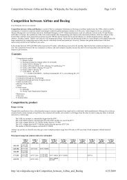
<strong>Load</strong> capacity (kN)<br />
10000<br />
8000<br />
6000<br />
4000<br />
2000<br />
0<br />
0.00m<br />
0.15m<br />
0.45m<br />
0.90m<br />
0 10 20 30 40 50 60 70 80 90<br />
Angle (degrees)<br />
Figure 17 – <strong>Load</strong> capacities for different flukes length<br />
consider<strong>in</strong>g a torpedo anchor with 4 flukes and soil B.<br />
Effect <strong>of</strong> the angle between the load direction and the plane <strong>of</strong><br />
the flukes<br />
FE meshes <strong>of</strong> an anchor with 4 flukes were constructed to<br />
evaluate the effect <strong>of</strong> the angle between the load and the plane<br />
<strong>of</strong> the flukes. Two sets <strong>of</strong> analyses were carried out: <strong>in</strong> the first<br />
group, called 45° analyses, loads were assumed to be at an<br />
angle <strong>of</strong> 45° with the plane <strong>of</strong> the flukes (plane 1, Fig. 11); <strong>in</strong><br />
the second group, called 0° analyses, loads were aligned with<br />
the flukes (plane 2, Fig. 11). Aga<strong>in</strong>, the anchor is supposed to<br />
be embedded <strong>in</strong> soil B.<br />
Figure 18 presents the estimated load capacities. From this<br />
figure, it is possible to observe that the load capacities for<br />
<strong>in</strong>cl<strong>in</strong>ations between 45° and 90° are equal, because, as po<strong>in</strong>ted<br />
out before, the failure mechanism is ruled by the vertical<br />
resistance <strong>of</strong> the anchor. For lower <strong>in</strong>cl<strong>in</strong>ations, the load<br />
capacities estimated for loads aligned with the flukes are<br />
slightly higher than the ones predicted when the loads are<br />
assumed to be between the flukes.<br />
Thus, the load angle with respect to the plane <strong>of</strong> the flukes<br />
does not alter the load capacity <strong>of</strong> the anchor. This po<strong>in</strong>ts to the<br />
conclusion that the lateral projected area <strong>of</strong> the anchor is not<br />
relevant to the total load capacity <strong>of</strong> the structure.<br />
<strong>Load</strong> capacity (kN)<br />
10000<br />
8000<br />
6000<br />
4000<br />
2000<br />
0<br />
0 10 20 30 40 50 60 70 80 90<br />
Angle (degrees)<br />
0°<br />
45°<br />
Figure 18 – <strong>Load</strong> capacities for different angles between the<br />
plane <strong>of</strong> the loads and the flukes. <strong>Torpedo</strong> anchor with 4<br />
flukes and soil B.<br />
CONCLUSIONS<br />
This paper presented a numerical based study on the<br />
undra<strong>in</strong>ed load capacity <strong>of</strong> a typical torpedo anchor embedded<br />
<strong>in</strong> a purely cohesive isotropic soil us<strong>in</strong>g a three-dimensional<br />
nonl<strong>in</strong>ear f<strong>in</strong>ite element (FE) model.<br />
In this model, the soil was simulated with solid elements<br />
capable <strong>of</strong> represent<strong>in</strong>g its nonl<strong>in</strong>ear physical behavior and the<br />
large deformations <strong>in</strong>volved. The torpedo anchor was also<br />
modeled with solid elements and its complex geometry was<br />
represented <strong>in</strong> detail. Moreover, the anchor-soil <strong>in</strong>teraction was<br />
addressed with contact f<strong>in</strong>ite elements that allow relative<br />
slid<strong>in</strong>g with friction between the surfaces <strong>in</strong> contact.<br />
Various analyses were conducted <strong>in</strong> order to understand the<br />
response <strong>of</strong> this type <strong>of</strong> anchor when different soil undra<strong>in</strong>ed<br />
shear strengths, load directions and number and width <strong>of</strong> flukes<br />
are considered.<br />
The obta<strong>in</strong>ed results po<strong>in</strong>ts to two different failure<br />
mechanisms:<br />
1. The first one mobilizes a great amount <strong>of</strong> soil and is<br />
directly related to its lateral resistance. This<br />
mechanism does not exhibit a clear load limit.<br />
2. The second one mobilizes a small amount <strong>of</strong> soil and<br />
is related to the vertical resistance <strong>of</strong> the soil. In this<br />
case, the load capacity is well characterized.<br />
Besides, the total contact area <strong>of</strong> the anchor and soil seems<br />
to be an important parameter <strong>in</strong> the determ<strong>in</strong>ation <strong>of</strong> its load<br />
capacity and, consequently, the <strong>in</strong>crease <strong>of</strong> the undra<strong>in</strong>ed shear<br />
strength and the number <strong>of</strong> flukes significantly <strong>in</strong>creases the<br />
load capacity <strong>of</strong> the torpedo anchor.<br />
12 Copyright © 2009 by ASME