Undrained Load Capacity of Torpedo Anchors in ... - laceo - UFRJ
Undrained Load Capacity of Torpedo Anchors in ... - laceo - UFRJ
Undrained Load Capacity of Torpedo Anchors in ... - laceo - UFRJ

You also want an ePaper? Increase the reach of your titles
YUMPU automatically turns print PDFs into web optimized ePapers that Google loves.
Contact properties<br />
As po<strong>in</strong>ted out before, surface to surface contact elements<br />
allow large relative displacement and separation between<br />
surfaces <strong>in</strong> contact. This task is performed with a contact<br />
detection algorithm based on the p<strong>in</strong>ball technique (Belytschko<br />
and Neal [7]) and contact forces evaluated with the augmented<br />
Lagrangian method (Belytschko et al. [8]).<br />
The augmented Lagrangian method consists <strong>of</strong> calculat<strong>in</strong>g<br />
a series <strong>of</strong> penalty forces dur<strong>in</strong>g the equilibrium iterations so<br />
that the f<strong>in</strong>al penetration between the two contact bodies is<br />
smaller than a value previously established. In the developed<br />
model, an allowable penetration <strong>of</strong> 0.1% <strong>of</strong> the smaller<br />
thickness between the two elements <strong>in</strong>itially <strong>in</strong> contact is<br />
adopted.<br />
Penalty forces are calculated by plac<strong>in</strong>g fictitious spr<strong>in</strong>gs<br />
along the contact boundaries <strong>of</strong> two bodies. When contact is<br />
established, these forces are applied to the nodal po<strong>in</strong>ts <strong>of</strong> the<br />
contact elements placed along the contact bodies. The forces<br />
are proportional to the penetration and a chosen penalty<br />
parameter, which can be physically <strong>in</strong>terpreted as the stiffness<br />
<strong>of</strong> the spr<strong>in</strong>gs.<br />
The choice <strong>of</strong> the stiffness <strong>of</strong> the spr<strong>in</strong>gs, called normal<br />
contact stiffness, f N , may be performed with relatively<br />
simplicity, but respect<strong>in</strong>g some rules. On the one hand, very<br />
high values may lead to numerical <strong>in</strong>stabilities and, on the other<br />
hand, very small values provoke violations <strong>of</strong> the contact<br />
conditions. Different estimates <strong>of</strong> contact normal stiffness<br />
proposed <strong>in</strong> Belytschko and Neal [7] and Benson and Hallquist<br />
[9], for <strong>in</strong>stance, po<strong>in</strong>ts to a value equivalent to the stiffness <strong>of</strong><br />
the elements <strong>in</strong> contact. Therefore, an estimate <strong>of</strong> the normal<br />
contact stiffness may be given by:<br />
E(<br />
z)<br />
fN<br />
z)<br />
= ⋅ Ac<br />
tc<br />
( (18)<br />
where t c is the smaller thickness <strong>of</strong> the two elements <strong>in</strong> contact<br />
and A c is the contact area between these elements.<br />
Another important aspect is the simulation <strong>of</strong> the relative<br />
slid<strong>in</strong>g between the soil and the torpedo anchor. Here, the<br />
Mohr-Coulomb friction model is used and, accord<strong>in</strong>g to API<br />
[10] may be expressed <strong>in</strong> the form:<br />
−0.5<br />
() z , ψ () z<br />
−0.25<br />
() z , ψ () z<br />
⎪<br />
⎧0.5<br />
⋅ψ<br />
≤ 1.0<br />
α () z = ⎨<br />
(21)<br />
⎪⎩ 0.5 ⋅ψ<br />
> 1.0<br />
where:<br />
( z)<br />
() z<br />
Su<br />
ψ () z =<br />
(22)<br />
p<br />
o<br />
F<strong>in</strong>ally, a stick stiffness, f T , must be def<strong>in</strong>ed to avoid large<br />
displacements between the two contact surfaces before the<br />
maximum shear stress is reached. In the proposed model, an<br />
expression similar to the one employed to the normal contact<br />
stiffness was adopted:<br />
G(<br />
z)<br />
fT<br />
( z)<br />
= ⋅ Ac<br />
(23)<br />
t<br />
c<br />
If a purely cohesive soil is modeled, Eq. (9) reduces to:<br />
( z) = α( z) ⋅ S ( z)<br />
τ (24)<br />
max<br />
u<br />
and only this <strong>in</strong>itial adhesion is considered by the contact<br />
elements.<br />
Initial stress state <strong>of</strong> the soil<br />
An important aspect <strong>of</strong> the anchor analysis is the<br />
simulation <strong>of</strong> the <strong>in</strong>itial stress state <strong>of</strong> the soil, i. e., the stresses<br />
<strong>in</strong> the soil prior to the imposition <strong>of</strong> any k<strong>in</strong>d <strong>of</strong> structural load<br />
to the anchor. As the proposed FE model does not simulate the<br />
anchor penetration <strong>in</strong> the soil, it is assumed, by hypothesis, that<br />
the anchor is loaded with the soil stress state undisturbed by the<br />
<strong>in</strong>stallation process. The anchor, thus, is supposed to be<br />
“wished <strong>in</strong> place”.<br />
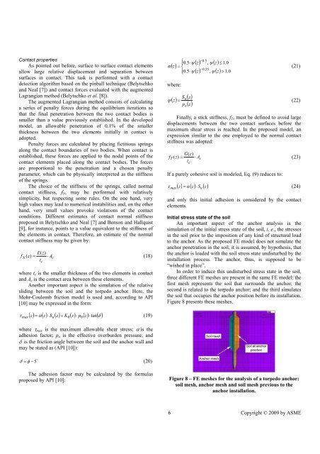
In order to <strong>in</strong>duce this undisturbed stress state <strong>in</strong> the soil,<br />
three different FE meshes are present <strong>in</strong> the same FE model: the<br />
first mesh represents the soil that surrounds the anchor; the<br />
second is related to the torpedo anchor; and the third simulates<br />
the soil that occupies the anchor position before its <strong>in</strong>stallation.<br />
Figure 8 presents these meshes.<br />
τ<br />
max<br />
( z) = α( z) ⋅ S ( z) + K ( z) ⋅ p ( z) tan( δ )<br />
u<br />
0 0 ⋅<br />
(19)<br />
where τ max is the maximum allowable shear stress; α is the<br />
adhesion factor; p o is the effective overburden pressure; and<br />
δ is the friction angle between the soil and the anchor wall and<br />
may be stated as (API [10]):<br />
o<br />
δ = φ − 5<br />
(20)<br />
The adhesion factor may be calculated by the formulas<br />
proposed by API [10]:<br />
Figure 8 – FE meshes for the analysis <strong>of</strong> a torpedo anchor:<br />
soil mesh, anchor mesh and soil mesh previous to the<br />
anchor <strong>in</strong>stallation.<br />
6 Copyright © 2009 by ASME