Undrained Load Capacity of Torpedo Anchors in ... - laceo - UFRJ
Undrained Load Capacity of Torpedo Anchors in ... - laceo - UFRJ
Undrained Load Capacity of Torpedo Anchors in ... - laceo - UFRJ

You also want an ePaper? Increase the reach of your titles
YUMPU automatically turns print PDFs into web optimized ePapers that Google loves.
where:<br />
σ y<br />
k VM = (13)<br />
3<br />
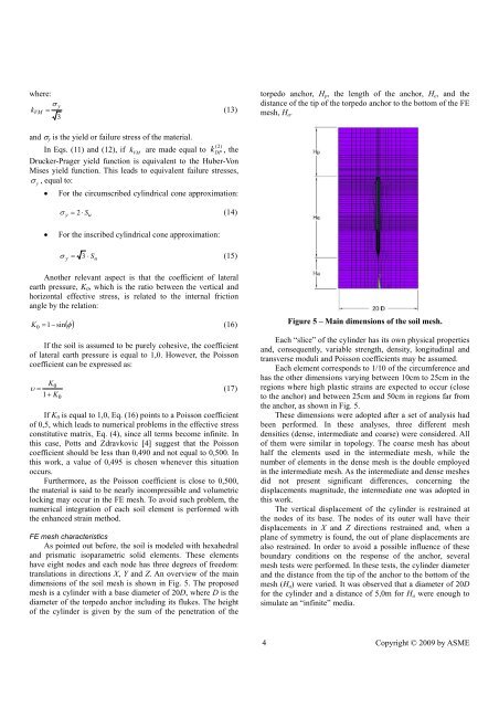
torpedo anchor, H p , the length <strong>of</strong> the anchor, H e , and the<br />
distance <strong>of</strong> the tip <strong>of</strong> the torpedo anchor to the bottom <strong>of</strong> the FE<br />
mesh, H a .<br />
and σ y is the yield or failure stress <strong>of</strong> the material.<br />
(2)<br />
In Eqs. (11) and (12), if k VM<br />
are made equal to k<br />
DP , the<br />
Drucker-Prager yield function is equivalent to the Huber-Von<br />
Mises yield function. This leads to equivalent failure stresses,<br />
σ<br />
y<br />
, equal to:<br />
• For the circumscribed cyl<strong>in</strong>drical cone approximation:<br />
σ y = 2 ⋅ S u<br />
(14)<br />
• For the <strong>in</strong>scribed cyl<strong>in</strong>drical cone approximation:<br />
σ y = 3 ⋅ S u<br />
(15)<br />
Another relevant aspect is that the coefficient <strong>of</strong> lateral<br />
earth pressure, K 0 , which is the ratio between the vertical and<br />
horizontal effective stress, is related to the <strong>in</strong>ternal friction<br />
angle by the relation:<br />
( )<br />
K 0 = 1−<br />
s<strong>in</strong> φ<br />
(16)<br />
If the soil is assumed to be purely cohesive, the coefficient<br />
<strong>of</strong> lateral earth pressure is equal to 1,0. However, the Poisson<br />
coefficient can be expressed as:<br />
K0<br />
υ =<br />
(17)<br />
1+<br />
K<br />
0<br />
If K 0 is equal to 1,0, Eq. (16) po<strong>in</strong>ts to a Poisson coefficient<br />
<strong>of</strong> 0,5, which leads to numerical problems <strong>in</strong> the effective stress<br />
constitutive matrix, Eq. (4), s<strong>in</strong>ce all terms become <strong>in</strong>f<strong>in</strong>ite. In<br />
this case, Potts and Zdravkovic [4] suggest that the Poisson<br />
coefficient should be less than 0,490 and not equal to 0,500. In<br />
this work, a value <strong>of</strong> 0,495 is chosen whenever this situation<br />
occurs.<br />
Furthermore, as the Poisson coefficient is close to 0,500,<br />
the material is said to be nearly <strong>in</strong>compressible and volumetric<br />
lock<strong>in</strong>g may occur <strong>in</strong> the FE mesh. To avoid such problem, the<br />
numerical <strong>in</strong>tegration <strong>of</strong> each soil element is performed with<br />
the enhanced stra<strong>in</strong> method.<br />
FE mesh characteristics<br />
As po<strong>in</strong>ted out before, the soil is modeled with hexahedral<br />
and prismatic isoparametric solid elements. These elements<br />
have eight nodes and each node has three degrees <strong>of</strong> freedom:<br />
translations <strong>in</strong> directions X, Y and Z. An overview <strong>of</strong> the ma<strong>in</strong><br />
dimensions <strong>of</strong> the soil mesh is shown <strong>in</strong> Fig. 5. The proposed<br />
mesh is a cyl<strong>in</strong>der with a base diameter <strong>of</strong> 20D, where D is the<br />
diameter <strong>of</strong> the torpedo anchor <strong>in</strong>clud<strong>in</strong>g its flukes. The height<br />
<strong>of</strong> the cyl<strong>in</strong>der is given by the sum <strong>of</strong> the penetration <strong>of</strong> the<br />
Figure 5 – Ma<strong>in</strong> dimensions <strong>of</strong> the soil mesh.<br />
Each “slice” <strong>of</strong> the cyl<strong>in</strong>der has its own physical properties<br />
and, consequently, variable strength, density, longitud<strong>in</strong>al and<br />
transverse moduli and Poisson coefficients may be assumed.<br />
Each element corresponds to 1/10 <strong>of</strong> the circumference and<br />
has the other dimensions vary<strong>in</strong>g between 10cm to 25cm <strong>in</strong> the<br />
regions where high plastic stra<strong>in</strong>s are expected to occur (close<br />
to the anchor) and between 25cm and 50cm <strong>in</strong> regions far from<br />
the anchor, as shown <strong>in</strong> Fig. 5.<br />
These dimensions were adopted after a set <strong>of</strong> analysis had<br />
been performed. In these analyses, three different mesh<br />
densities (dense, <strong>in</strong>termediate and coarse) were considered. All<br />
<strong>of</strong> them were similar <strong>in</strong> topology. The coarse mesh has about<br />
half the elements used <strong>in</strong> the <strong>in</strong>termediate mesh, while the<br />
number <strong>of</strong> elements <strong>in</strong> the dense mesh is the double employed<br />
<strong>in</strong> the <strong>in</strong>termediate mesh. As the <strong>in</strong>termediate and dense meshes<br />
did not present significant differences, concern<strong>in</strong>g the<br />
displacements magnitude, the <strong>in</strong>termediate one was adopted <strong>in</strong><br />
this work.<br />
The vertical displacement <strong>of</strong> the cyl<strong>in</strong>der is restra<strong>in</strong>ed at<br />
the nodes <strong>of</strong> its base. The nodes <strong>of</strong> its outer wall have their<br />
displacements <strong>in</strong> X and Z directions restra<strong>in</strong>ed and, when a<br />
plane <strong>of</strong> symmetry is found, the out <strong>of</strong> plane displacements are<br />
also restra<strong>in</strong>ed. In order to avoid a possible <strong>in</strong>fluence <strong>of</strong> these<br />
boundary conditions on the response <strong>of</strong> the anchor, several<br />
mesh tests were performed. In these tests, the cyl<strong>in</strong>der diameter<br />
and the distance from the tip <strong>of</strong> the anchor to the bottom <strong>of</strong> the<br />
mesh (H a ) were varied. It was observed that a diameter <strong>of</strong> 20D<br />
for the cyl<strong>in</strong>der and a distance <strong>of</strong> 5,0m for H a were enough to<br />
simulate an “<strong>in</strong>f<strong>in</strong>ite” media.<br />
4 Copyright © 2009 by ASME