Undrained Load Capacity of Torpedo Anchors in ... - laceo - UFRJ
Undrained Load Capacity of Torpedo Anchors in ... - laceo - UFRJ
Undrained Load Capacity of Torpedo Anchors in ... - laceo - UFRJ

Create successful ePaper yourself
Turn your PDF publications into a flip-book with our unique Google optimized e-Paper software.
<strong>Torpedo</strong> anchors were first employed to hold flexible risers where [ Δσ] = [ Δσ<br />
] T<br />
xx Δσ<br />
yy Δσ<br />
zz Δτ<br />
xy Δτ<br />
xz Δτ<br />
yz is the<br />
just after their touchdown po<strong>in</strong>ts (TDP) <strong>in</strong> order to avoid that<br />
the loads generated by the float<strong>in</strong>g units movements were<br />
<strong>in</strong>cremental total stress vector;<br />
transferred to subsea equipments such as wet Christmas trees [ Δε<br />
] = [ Δε<br />
] T<br />
xx Δε<br />
yy Δε<br />
zz Δγ<br />
xy Δγ<br />
xz Δγ<br />
yz is the <strong>in</strong>cremental<br />
(Medeiros Jr. [1]). In 2003, a high hold<strong>in</strong>g capacity torpedo total stra<strong>in</strong> vector; and [ D<br />
ep<br />
] is the constitutive elasto-plastic<br />
anchor was designed to susta<strong>in</strong> the loads imposed by the<br />
matrix (Potts and Zdravkovic [4]):<br />
moor<strong>in</strong>g l<strong>in</strong>es <strong>of</strong> Petrobras FPSO P-50 (Araújo et al. [2]). S<strong>in</strong>ce<br />
E<br />
[ Δσ] [ Dep ] [ Δε]<br />
K s =<br />
3⋅<br />
1−<br />
2⋅υ<br />
(6)<br />
then, other float<strong>in</strong>g production systems have been anchored<br />
T<br />
us<strong>in</strong>g the torpedo concept (Brandão et al. [3]).<br />
⎧∂P<br />
[ ]<br />
([ σ] ,[ m]<br />
) ⎫ ⎧∂F( [ σ][ , k]<br />
) ⎫<br />
D ⋅ ⎨ ⎬ ⋅ ⎨ ⎬ ⋅ [ D]<br />
Despite its large use <strong>in</strong> Brazilian <strong>of</strong>fshore applications, the<br />
[<br />
calculus <strong>of</strong> the torpedo anchor load capacity and the prediction<br />
] [ ]<br />
⎩ ∂σ<br />
⎭ ⎩ ∂σ<br />
= D −<br />
⎭<br />
T<br />
⎧∂F( [ σ][ , k]<br />
) ⎫ ⎧∂P<br />
<strong>of</strong> the stresses <strong>in</strong> its structure due to the loads imposed by the<br />
[ ]<br />
([ σ][ m]<br />
) ⎫<br />
⎨ ⎬ ⋅ D ⋅ ⎨<br />
⎬<br />
⎩ ∂σ<br />
⎭ ⎩ ∂σ<br />
⎭<br />
attached moor<strong>in</strong>g l<strong>in</strong>e rema<strong>in</strong>s as a great challenge. Thus,<br />
(2)<br />
aim<strong>in</strong>g at accomplish<strong>in</strong>g these tasks, a nonl<strong>in</strong>ear threedimensional<br />
f<strong>in</strong>ite element (FE) model is here proposed. This<br />
where [ D ] is the elastic total stress constitutive matrix;<br />
model employs isoparametric solid elements to represent both P ([ σ ],<br />
[ m]<br />
) is the plastic potential function; F ([ σ ],<br />
[ k]<br />
) is the<br />
the soil and the anchor. These elements are capable <strong>of</strong> yield function; [ σ ] is the stress state <strong>in</strong> the element; [ m ] and<br />
represent<strong>in</strong>g the physical nonl<strong>in</strong>ear behavior <strong>of</strong> the soil and, [ k ] are state parameters related to the plastic potential and yield<br />
eventually, <strong>of</strong> the anchor. Large deformations may also be<br />
functions, respectively.<br />
accounted for. Soil-anchor <strong>in</strong>teraction is assured by surface to<br />
The elastic total stress constitutive matrix can be split <strong>in</strong><br />
surface contact elements placed on the external surface <strong>of</strong> the<br />
two parts, as follows:<br />
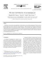
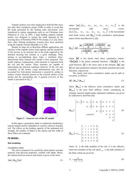
anchor and the surround<strong>in</strong>g soil. A general overview <strong>of</strong> this<br />
model is presented <strong>in</strong> Fig. 2.<br />
[ D ] = [ D eff ] + [ D pore ]<br />
(3)<br />
where [ D<br />
eff<br />
] is the effective stress constitutive matrix and<br />
[ D<br />
pore<br />
] is the pore fluid stiffness, which, consider<strong>in</strong>g an<br />
isotropic material loaded under undra<strong>in</strong>ed conditions, are given<br />
by (Zdravkovic and Potts [4]):<br />
⎡ 4 2 2<br />
⎤<br />
⎢K<br />
s + ⋅G<br />
K s − ⋅G<br />
K s − ⋅G<br />
0 0 0<br />
3 3 3<br />
⎥<br />
⎢<br />
4 2<br />
⎥<br />
⎢<br />
K<br />
⎥<br />
s + ⋅G<br />
K s − ⋅G<br />
0 0 0<br />
⎢<br />
3 3<br />
⎥<br />
[ D ] = ⎢<br />
4<br />
⎥<br />
eff<br />
⎢<br />
K s + ⋅G<br />
0 0 0<br />
3<br />
⎥<br />
⎢<br />
symmetric<br />
G 0 0 ⎥<br />
⎢<br />
⎥<br />
⎢<br />
G 0 ⎥<br />
Figure 2 – General view <strong>of</strong> the FE model.<br />
⎢<br />
⎥<br />
⎣<br />
G⎦<br />
(4)<br />
In this paper, a parametric study is conducted consider<strong>in</strong>g a<br />
typical torpedo anchor embedded <strong>in</strong> a purely cohesive isotropic<br />
⎡1<br />
1 1 0 0 0⎤<br />
soil. The effects on the hold<strong>in</strong>g capacity <strong>of</strong> the undra<strong>in</strong>ed soil<br />
⎢<br />
⎥<br />
strength, the number <strong>of</strong> flukes <strong>in</strong> the anchor and the width <strong>of</strong><br />
⎢<br />
1 1 1 0 0 0<br />
⎥<br />
⎢1<br />
1 1 0 0 0⎥<br />
these flukes are evaluated.<br />
[ D pore ] = K pore ⋅ ⎢<br />
⎥<br />
(5)<br />
⎢0<br />
0 0 0 0 0⎥<br />
⎢<br />
⎥<br />
FE MODEL<br />
0 0 0 0 0 0<br />
⎢<br />
⎥<br />
⎢⎣<br />
0 0 0 0 0 0⎥⎦<br />
Soil model<strong>in</strong>g<br />
where K<br />
s<br />
is the bulk modulus <strong>of</strong> the soil, G is the effective<br />
Constitutive matrix<br />
The soil is assumed to be a perfectly elasto-plastic isotropic transverse modulus <strong>of</strong> the soil and K<br />
pore<br />
is the bulk modulus <strong>of</strong><br />
material with physical properties variable with depth. Hence, the fluid, which are given by:<br />
the relation between stresses and stra<strong>in</strong>s is given <strong>in</strong> the form:<br />
( )<br />
2 Copyright © 2009 by ASME